EP0419985A1 - Sliding roof and/or sliding lifting roof, especially for motor vehicles - Google Patents
Sliding roof and/or sliding lifting roof, especially for motor vehicles Download PDFInfo
- Publication number
- EP0419985A1 EP0419985A1 EP90117817A EP90117817A EP0419985A1 EP 0419985 A1 EP0419985 A1 EP 0419985A1 EP 90117817 A EP90117817 A EP 90117817A EP 90117817 A EP90117817 A EP 90117817A EP 0419985 A1 EP0419985 A1 EP 0419985A1
- Authority
- EP
- European Patent Office
- Prior art keywords
- sunroof
- bellows
- cover
- bellows part
- sections
- Prior art date
- Legal status (The legal status is an assumption and is not a legal conclusion. Google has not performed a legal analysis and makes no representation as to the accuracy of the status listed.)
- Withdrawn
Links
Images

Classifications
-
- B—PERFORMING OPERATIONS; TRANSPORTING
- B60—VEHICLES IN GENERAL
- B60J—WINDOWS, WINDSCREENS, NON-FIXED ROOFS, DOORS, OR SIMILAR DEVICES FOR VEHICLES; REMOVABLE EXTERNAL PROTECTIVE COVERINGS SPECIALLY ADAPTED FOR VEHICLES
- B60J7/00—Non-fixed roofs; Roofs with movable panels, e.g. rotary sunroofs
- B60J7/0007—Non-fixed roofs; Roofs with movable panels, e.g. rotary sunroofs moveable head-liners, screens, curtains or blinds for ceilings
- B60J7/0046—Non-fixed roofs; Roofs with movable panels, e.g. rotary sunroofs moveable head-liners, screens, curtains or blinds for ceilings side blind between roof and panel in vent mode
Definitions
- the invention relates to a sunroof and / or sunroof, in particular for motor vehicles, with a roof opening formed in the fixed roof part, guide rails running on opposite sides of the roof opening and a cover which closes the roof opening in its closed position and which at least after lowering its rear edge along the guide rails is partially slidable under the fixed roof part and which can optionally be extended with its rear edge over the fixed roof part, with a visor in the form of a concertina-like bellows part with longitudinal bellows folds for covering, which deforms flexibly when the cover rear edge is adjusted in the vertical direction a gap is formed between the underside of the lid and the guide rails.
- the bellows part has a uniform wall thickness in cross-section and the bellows part has longitudinal bellows folds, so that this bellows can be pulled apart or compressed according to the height of the cover to cover a gap between the underside of the cover and the guide rails, so that the functional parts located there are not visible are.
- the bellows parts between the bellows folds in accordion-like fashion compressed state alternately bend inside and outside and the bellows part overall has a uniform cross-sectional thickness
- the bellows parts on the bellows folds are connected to each other via a transition radius, so that when the bellows part is fully compressed, the height of the bellows parts due to the transition radius parts formed on the bellows folds and the number the respective wall thicknesses of the bellows sections is determined.
- the bellows sections do not lie completely flat in the vertical direction in the compressed state. Therefore, the known bellows part has a relatively large overall height due to the transition radius sections on the longitudinal bellows folds, so that difficulties arise in particular in the case of so-called flat sunroofs and / or sunroofs.
- the invention aims to provide a sunroof and / or a sunroof, which is particularly intended for motor vehicles, in which a screen with the smallest possible height is provided.
- a sunroof and / or sunroof in particular for motor vehicles, has a roof opening formed in the fixed roof part, guide rails running on opposite sides of the roof opening and a cover which, in its closed position, closes the roof opening which, after lowering its rear edge, runs along the Guide rails can be at least partially slid under the fixed roof part and which can optionally be extended with its rear edge over the fixed roof part, with a visor in the form of an accordion-type bellows part with longitudinal bellows folds that deforms flexibly when the cover rear edge is adjusted in the vertical direction on both sides of the cover to cover a gap formed between the underside of the cover and the guide rails is attached, characterized in that the longitudinal bellows folds of transition sections thinner than the bellows sections in cross section are formed between two successive bellows sections.
- the wall thickness of the bellows part is not uniform, but rather the successive bellows sections are connected via transition sections which are thinner in cross-section and which form the longitudinal bellows folds.
- transition sections are preferably designed as thin, hinge-like web parts, so that the entire bellows part can be formed as a one-piece part and the web parts form connecting webs between respectively adjacent bellows sections.
- the design of the screen in the sunroof and / or sunroof according to the invention is preferably such that the bellows sections of the bellows part lie flat on one another in the compressed state, which also improves the lateral stability of the bellows part.
- the lower end facing the guide rail and / or the cover underside facing upper end of the bellows part also thickened with respect to the bellows sections, since at least one of these ends serves as a holder and the other serves as a contact surface, so that these ends are inherently more rigid and rigid to reliably perform their intended function.
- the lower end of the bellows part which is of thickened design, is held on a guide bracket which is only attached to the front part on the underside or inside of the cover.
- the design is such that the bellows part is automatically pressed against the required pull-out position in such a way that the gap formed between the cover and the guide rail is always reliably covered. Since with this design the bellows part does not need to be attached directly to the cover or its frame part, the assembly of the screen is made easier.
- a spring element is provided for spring loading of the bellows part, which has two legs which extend essentially in the longitudinal direction of the bellows part and which cooperate with the respective upper and lower ends of the bellows part.
- the spring element is preferably designed as a shaped wire spring.
- a hook element can be assigned to the upper end of the bellows part, through which, for example, one leg of the spring element passes, and that in a form-fitting manner with a correspondingly projecting part engages on the underside of the cover with the support of the spring force of the spring element.
- an alternative embodiment is characterized in that the bellows part has at least one layer of material on which very thin, in the area of the bellows sections Stiffening strips running in the longitudinal direction, mutually spaced apart, are fastened such that the longitudinal bellows folds are formed between two successive stiffening strips.
- a fabric layer is stiffened with the aid of stiffening strips, which gives the bellows part lateral stability, so that the bellows part resists the wind forces.
- the bellows part has a greater inherent torsional rigidity than that of parts made entirely of plastic, in order to achieve improved functionality.
- the bellows part has a collapsed state, for example with the lid of the sunroof and / or sunroof closed an extremely low overall height. This design of the bellows part is extremely flat.
- the bellows part preferably comprises two layers of fabric, and the stiffening strips are inserted between the two layers of fabric.
- the inward-facing fabric layer is preferably, that is Layer of fabric, which faces the vehicle interior and is visible from the inside when the cover is in the appropriate position, is designed as a decorative layer, which can be adapted in particular to the color of the interior of the vehicle in terms of color. This gives in particular an appealing exterior of a screen for a sunroof and / or sunroof according to the invention.
- the manufacture of the bellows part can be simplified in particular in that the respectively facing surfaces of the layers of fabric are self-adhesive.
- the stiffening strips of the desired arrangement are then fixed directly to the layers of material by means of adhesive.
- the bellows part of the type described above is preferably articulated to a sliding roof and / or sliding / lifting roof according to the invention via a supporting part on the front inside of the cover. Only by utilizing gravity can the bellows part be unfolded as a screen if, for example, the cover of a sliding roof Occupies the installation position.
- An adhesive connection is preferably provided to connect the bellows part to the supporting part.
- a motor vehicle designated overall by 1 has, for example, a roof part which is designed as a sliding / tilting roof 2 in accordance with the illustrated embodiment.
- a roof opening 4 is formed, along the two long sides of which guide rails 5 run.
- a cover 6 is slidable along the guide rails 5, the cover 6 closing the roof opening 4 in its closed position and being slidable under the fixed roof part 3 after lowering its rear edge 7.
- the rear edge 7 of the cover 6 can optionally be raised over the fixed roof part 3.
- the lid can be made of a translucent or translucent material, i.e. be designed as a so-called glass lid.
- the cover 6 or the like for example, from sheet steel. be made, in which case it is not translucent.
- a circumferential frame 8 is inserted into the roof opening 4 delimited by the fixed roof part 3 and carries the guide rails 5 and a drive device (not shown in more detail) for the movement of the cover 6.
- a sliding headlining 9 can be provided pointing in the direction of the vehicle interior, which is also mounted on corresponding guides so as to be longitudinally movable.
- the sliding headliner 9 is formed by a headliner part 10, which is connected via a clip connection 11 to a support part 12, which is guided in a longitudinally displaceable manner.
- the cover 6 is formed by a so-called glass cover, it can be used on the inside by one as the inside of the cover sheet metal frame part 13 are carried, on which the necessary links are mounted with the roof drive, not shown.
- a flexible concertina-like screen 14 is explained in more detail below.
- This screen serves to cover a gap C between the underside of the cover 6 and the guide rail 5. Both in the position of the cover 6, which is not shown, and in the closed position thereof, a space D is formed, in which the passenger compartment can be reached if no special precautions are taken.
- the gap C between the cover 6 and the guide rail 5 changes as a function of the height of the cover 6.
- the cover 6 assumes approximately its closed position, in which the gap C has its average size, while the gap C is larger when the cover 6 is open and somewhat smaller when the cover 6 is moved into its open position.
- the screen 14 in FIG. 2 assumes an average central position, in which it is neither fully extended nor fully compressed.
- the screen 14 is formed by a bellows part 15, designated overall by 15.
- this bellows part 15 comprises bellows sections 16, each of which has a matching cross-sectional thickness, and which are connected to one another via transition sections 17, which form the respective bellows folds 18, which run in the longitudinal direction of the bellows part 15.
- transition sections 17 In cross section, these transition sections 17 have a thickness which is substantially reduced in comparison to the bellows sections 16, so that they form web parts 19 which act like a hinge when the bellows part 15 is compressed and pulled apart.
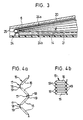
- FIG. 4a shows a section of the bellows part 15 separately in a side view, the bellows part 15 being shown in a partially pulled-apart position.
- FIG. 4b on the other hand, the bellows part 15 is shown in its fully compressed position, which it assumes, for example, when the cover is at least partially displaced under the fixed roof part 3 along the guide rails 5 after lowering its rear edge and the gap C is the smallest.
- the overall height of the bellows part 15 in the fully compressed state thereof is determined solely by the number and the respective cross-sectional thickness of the bellows sections 16, while the transition sections 17 have no influence on this, since these only form a hinge-like articulation at the transition points.
- transition sections 17, which are reduced in cross-sectional thickness, enable the bellows part 15 to be pulled apart more or less with relatively low actuating forces, if necessary to adapt to the respective position of the cover 6 and the size of the gap C.
- the bellows part 15 according to the preferred embodiment described above can also be used in so-called flat sliding roofs and / or sunroofs 2 as a visor 14, since thanks to this design the bellows part 15 has an extremely low overall height when compressed.
- the upper end 20, ie the end of the bellows part 15 facing the cover 6 and / or the lower end 21, ie the end of the bellows part 15 facing the guide rail 5, is transverse cut thicker, so that these ends 20, 21 are stiffer and more rigid and can be used as support parts and / or holding parts for the bellows part 15 of the screen 14.
- the lower, thickened end 21 of the bellows part 15 is held according to FIG. 2 on a guide bracket 22, which is expediently fastened, for example, only on the front part (not shown in detail) to the underside or inside of the cover 6.
- the bellows part 15 of the screen 14 is carried along with the aid of the guide bracket 22 during the movement of the cover 6 in a corresponding manner in order to cover the gap C formed in each position in such a way that the functional parts of the sliding / lifting roof 2 behind it are not visible are.
- a preferred embodiment of the screen 14 is shown with reference to FIGS. 2 and 3.
- This screen 14 can automatically contact the bottom 6 of the cover 6 without a mechanical connection to the underside of the cover 6.
- the bellows part 15 is assisted by a spring force, automatically brought into the respective spread position to cover the gap C.
- a spring element 24 is provided, which extends essentially in the longitudinal direction of the bellows part 15.
- the spring element 24 has two legs 24a, 24b which also run in the longitudinal direction of the bellows part 15 and which cooperate with the upper end 20 and the lower end 21 of the bellows part 15. These legs 24a, 24b are expediently inserted into the respectively thickened upper and lower ends 20, 21 of the bellows part 15.
- the spring element 24 is designed in the form of a shaped wire spring 25.
- a positive connection 23 is provided at the upper end 20 of the bellows part 15.
- a hook part 26 is attached, which in the respective extended position of the screen 14 engages in a projecting part on the underside of the cover.
- One leg 24a of the spring element 24 can be inserted into this hook part 26.
- a corresponding automatic display of the screen and / or the bellows part 15 can also be achieved in that the bellows folds 18 or the like with the appropriate choice of material. gives a suitable inherent rigidity.
- this upper end 20 of the bellows part 15 can also be fixed on the frame part 13 and pressed against the underside of the cover 6.
- a positive connection 23 can be provided according to FIG. 2, by means of which the bellows part 15 rests reliably at its upper end 20 on the inside of the cover 6 in each respective exhibition.
- sliding headliner 9 shown in FIG. 2 does not necessarily have to be provided, but rather it is a selectable additional part.
- the formation of the bellows part 15 of the screen is also 14 is not limited to the details shown in the figures of the drawing, but depending on the respective requirements, for example, the cross-sectional thicknesses of the bellows section 16 can also be selected differently, although all these possible design variants have in common that the bellows sections 16 have hinge-like web parts 19 are connected to reduce the overall height of the bellows part 15.
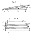
- FIG. 5 and 6 an alternative embodiment of a bellows part is shown, which is designated 15 'to distinguish it from the above-described embodiments.
- This bellows part 15' serves as a screen 14 ', as explained in connection with the above-described embodiments is.
- Fig. 6 the bellows part 15 'is shown in the unfolded state before installation in a sunroof and / or sunroof.
- stiffening strips 31 extending in the longitudinal direction are placed on a first material layer 30 and. firmly connected to the first layer of material 30. The stiffening strips 31 are mutually at such a distance that between two consecutive stiffening strips 31 in the installed state of the bellows part 15 'bellows folds 18' are formed.
- the stiffening strips 31 thus extend over the area of the two sections 16 'of the bellows part 15'.
- the stiffening strips 31 On one side, in Figures 5 and 6 on the left side, the stiffening strips 31 have openings 32 through which a rigid part such as a pin or bolt can be threaded after folding the bellows part 15 '.
- a rigid part such as a pin or bolt
- This is particularly expedient with regard to assembly and disassembly, since the bellows part 15 'thus remains together as a unit in the folded state.
- this also prevents lateral displacements of the stiffening strips 31 in the installed state, so that sufficient lateral stability against wind forces in the built-in state is prevented State of the screen 14 'receives.
- the first layer of fabric 30 is the layer of fabric which faces inward in the installed state of the screen 14, it can be designed as a decorative layer and adapted to the respective color of the vehicle interior in order to achieve an appealing exterior of the screen 14.
- a second fabric layer 33 can be placed on the arrangement of first fabric layer 30 and stiffening strip 31 shown in FIG. 6.
- layers of fabric 30 and 33 can be used here, which are self-adhesive on one side, so that they can only be firmly connected to one another by stacking and pressing together, the stiffening strips 31 being an intermediate layer between the two layers of fabric 30 , 33 are arranged.
- the screen 14 ' is shown in a partially unfolded state.
- the bellows part 15 ' is expediently attached to a support part 34 by gluing, which in turn is articulated, for example, on an inner cover plate 35. This articulation is preferably provided in the front area of the cover 6.
- the screen 14 ' is advantageously carried out with the help of a guide part, which is not shown, with the movement mechanism of the sunroof and / or sunroof, this guide is preferably provided in the lower region of the sunroof or sunroof.
Landscapes
- Engineering & Computer Science (AREA)
- Mechanical Engineering (AREA)
- Seal Device For Vehicle (AREA)
Abstract
Description
Die Erfindung betrifft ein Schiebedach und/oder Schiebehebedach, insbesondere für Kraftfahrzeuge, mit einer im festen Dachteil ausgebildeten Dachöffnung, an gegenüberliegenden Seiten der Dachöffnung verlaufenden Führungsschienen und einem Deckel, der in seiner Schließstellung die Dachöffnung verschließt, der nach Absenken seiner Hinterkante entlang den Führungsschienen mindestens teilweise unter das feste Dachteil schiebbar ist und der gegebenenfalls wahlweise mit seiner Hinterkante über das feste Dachteil ausstellbar ist, wobei an beiden Seiten des Deckels eine sich beim Verstellen der Deckelhinterkante in lotrechter Richtung flexibel verformende Sichtblende in Form eines ziehharmonikaartigen Faltenbalgenteils mit längs verlaufenden Balgenfalten zum Abdecken eines zwischen der Deckelunterseite und den Führungsschienen gebildeten Spalts angebracht ist.The invention relates to a sunroof and / or sunroof, in particular for motor vehicles, with a roof opening formed in the fixed roof part, guide rails running on opposite sides of the roof opening and a cover which closes the roof opening in its closed position and which at least after lowering its rear edge along the guide rails is partially slidable under the fixed roof part and which can optionally be extended with its rear edge over the fixed roof part, with a visor in the form of a concertina-like bellows part with longitudinal bellows folds for covering, which deforms flexibly when the cover rear edge is adjusted in the vertical direction a gap is formed between the underside of the lid and the guide rails.
Aus DE-PS 33 08 065 sind ein Schiebedach und ein Schiebehebedach mit einer flexiblen Sichtblende der vorstehend genannten Art bekannt. Der Faltenbalgenteil hat hierbei im Querschnitt eine einheitliche Wandstärke und der Balgenteil hat längsverlaufende Balgenfalten, so daß dieser Balgen entsprechend der Höhenlage des Deckels auseinandergezogen oder zusammengedrückt werden kann, um einen Spalt zwischen der Deckelunterseite und den Führungsschienen abzudecken, so daß die dort liegenden Funktionsteile nicht sichtbar sind. Da sich die Faltenbalgenabschnitte zwischen den Balgenfalten ziehharmonikaartig im zu sammengedrückten Zustand jeweils abwechselnd innen und außen krümmen und der Balgenteil insgesamt eine einheitliche Querschnittsstärke hat, sind die Faltenbalgenteile an den Balgenfalten über einen Übergangsradius untereinander verbunden, so daß im vollständig zusammengedrückten Zustand des Faltenbalgenteils die Höhe desselben durch die an den Balgenfalten gebildeten Übergangsradiusteile und die Anzahl der jeweiligen Wandstärken der Balgenabschnitte bestimmt ist. Dies bedeutet, daß die Faltenbalgenabschnitte im zusammengedrückten Zustand nicht vollständig flächig in Höhenrichtung aufeinanderliegen. Daher hat der bekannte Faltenbalgenteil aufgrund der Übergangsradiusabschnitte an den längs verlaufenden Balgenfalten eine relativ große Bauhöhe, so daß sich Schwierigkeiten hierbei insbesondere bei sogenannten flach bauenden Schiebedächern und/oder Schiebehebedächern ergeben.From DE-PS 33 08 065 a sunroof and a sunroof with a flexible screen of the type mentioned above are known. The bellows part has a uniform wall thickness in cross-section and the bellows part has longitudinal bellows folds, so that this bellows can be pulled apart or compressed according to the height of the cover to cover a gap between the underside of the cover and the guide rails, so that the functional parts located there are not visible are. Since the bellows sections between the bellows folds in accordion-like fashion compressed state alternately bend inside and outside and the bellows part overall has a uniform cross-sectional thickness, the bellows parts on the bellows folds are connected to each other via a transition radius, so that when the bellows part is fully compressed, the height of the bellows parts due to the transition radius parts formed on the bellows folds and the number the respective wall thicknesses of the bellows sections is determined. This means that the bellows sections do not lie completely flat in the vertical direction in the compressed state. Therefore, the known bellows part has a relatively large overall height due to the transition radius sections on the longitudinal bellows folds, so that difficulties arise in particular in the case of so-called flat sunroofs and / or sunroofs.
Die Erfindung zielt darauf ab, ein Schiebedach und/oder ein Schiebehebedach, das insbesondere für Kraftfahrzeuge bestimmt ist, bereitzustellen, bei dem eine Sichtblende mit möglichst geringer Bauhöhe vorgesehen ist.The invention aims to provide a sunroof and / or a sunroof, which is particularly intended for motor vehicles, in which a screen with the smallest possible height is provided.
Nach der Erfindung zeichnet sich ein Schiebedach und/oder Schiebehebedach, insbesondere für Kraftfahrzeuge, mit einer im festen Dachteil ausgebildeten Dachöffnung, an gegenüberliegenden Seiten der Dachöffnung verlaufenden Führungsschienen und einem Deckel, der in seiner Schließstellung die Dachöffnung verschließt, der nach Absenken seiner Hinterkante entlang den Führungsschienen mindestens teilweise unter das feste Dachteil schiebbar ist und der gegebenenfalls wahlweise mit seiner Hinterkante über das feste Dachteil ausstellbar ist, wobei an beiden Seiten des Deckels eine sich beim Verstellen der Deckelhinterkante in lotrechter Richtung flexibel verformende Sichtblende in Form eines ziehharmonikaartigen Faltenbalgteils mit längs verlaufenden Balgenfalten zum Abdecken eines zwischen der Deckelunterseite und den Führungsschienen gebildeten Spalts angebracht ist, dadurch aus, daß die längsverlaufenden Balgenfalten von im Vergleich zu den Balgenabschnitten im Querschnitt dünneren Übergangsabschnitten zwischen jeweils zwei aufeinanderfolgenden Balgenabschnitten gebildet werden.According to the invention, a sunroof and / or sunroof, in particular for motor vehicles, has a roof opening formed in the fixed roof part, guide rails running on opposite sides of the roof opening and a cover which, in its closed position, closes the roof opening which, after lowering its rear edge, runs along the Guide rails can be at least partially slid under the fixed roof part and which can optionally be extended with its rear edge over the fixed roof part, with a visor in the form of an accordion-type bellows part with longitudinal bellows folds that deforms flexibly when the cover rear edge is adjusted in the vertical direction on both sides of the cover to cover a gap formed between the underside of the cover and the guide rails is attached, characterized in that the longitudinal bellows folds of transition sections thinner than the bellows sections in cross section are formed between two successive bellows sections.
Bei diesem erfindungsgemäß ausgelegten Schiebedach und/oder Schiebehebedach ist die Wandstärke des Balgenteils nicht einheitlich, sondern die jeweils aufeinanderfolgenden Balgenabschnitte sind über im Querschnitt dünner bemessene Übergangsabschnitte verbunden, welche die längs verlaufenden Balgenfalten bilden. Hierdurch erhält man eine Sichtblende mit kleinerer Bauhöhe als bisher üblich, wenn der Balgenteil sich im zusammengedrückten Zustand befindet, da gerade in diesem Zustand die Balgenabschnitte flächig direkt aufeinander aufliegen, so daß die Bauhöhe des Faltenbalgteils der Sichtblende im wesentlichen nur durch die Wandstärke und die Anzahl der Balgenabschnitte bestimmt ist, während die im Querschnitt dünner bemessenen Übergangsabschnitte keinen Einfluß auf die Bauhöhe der Sichtblende haben.In this sunroof and / or sunroof designed according to the invention, the wall thickness of the bellows part is not uniform, but rather the successive bellows sections are connected via transition sections which are thinner in cross-section and which form the longitudinal bellows folds. This gives a screen with a smaller overall height than usual when the bellows part is in the compressed state, because in this state the bellows sections lie flat directly on top of each other, so that the overall height of the bellows part of the screen essentially only by the wall thickness and the number of the bellows sections is determined, while the transition sections, which are thinner in cross-section, have no influence on the overall height of the screen.
Vorzugsweise sind die Übergangsabschnitte als dünne, scharnierartig wirkende Stegteile ausgebildet, so daß das gesamte Faltenbalgenteil als einstückiges Teil ausgebildet werden kann und die Stegteile Verbindungsstege zwischen jeweils benachbarten Balgenabschnitten bilden.The transition sections are preferably designed as thin, hinge-like web parts, so that the entire bellows part can be formed as a one-piece part and the web parts form connecting webs between respectively adjacent bellows sections.
Vorzugsweise ist die Auslegung der Sichtblende beim erfindungsgemäßen Schiebedach und/oder Schiebehebedach derart getroffen, daß die Balgenabschnitte des Faltenbalgenteils in zusammengedrücktem Zustand flächig aufeinanderliegen, wodurch auch die Seitenstabilität des Faltenbalgenteils verbessert wird.The design of the screen in the sunroof and / or sunroof according to the invention is preferably such that the bellows sections of the bellows part lie flat on one another in the compressed state, which also improves the lateral stability of the bellows part.
Gemäß einer bevorzugten Ausgestaltungsform sind das der Führungsschiene zugewandte untere Ende und/oder das der Deckel unterseite zugewandte obere Ende des Balgenteils auch gegenüber den Balgenabschnitten verdickt ausgebildet, da wenigstens eines dieser Enden als Halterung und das jeweils andere als Anlagefläche dient, so daß diese Enden in sich starrer und steifer sind, um ihre bestimmungsgemäße Funktion zuverlässig zu erfüllen.According to a preferred embodiment, the lower end facing the guide rail and / or the cover underside facing upper end of the bellows part also thickened with respect to the bellows sections, since at least one of these ends serves as a holder and the other serves as a contact surface, so that these ends are inherently more rigid and rigid to reliably perform their intended function.
Gemäß einer bevorzugten Ausführungsform ist das untere Ende des Balgenteils, welches verdickt ausgebildet ist, an einem Führungsbügel gehalten, der nur am vorderen Teil an der Deckelunterseite oder Deckelinnenseite befestigt ist. Durch diese Verbindung des Balgenteils über den Führungsbügel mit dem Deckel wird das die Sichtblende bildende Balgenteil jeweils bei der Verschiebebewegung und/oder der Ausstellbewegung des Deckels zwangsläufig mitgenommen, wobei man auf diese Weise eine konstruktiv äußerst einfache Verbindung mit dem beweglichen Deckelteil und der Sichtblende erhält.According to a preferred embodiment, the lower end of the bellows part, which is of thickened design, is held on a guide bracket which is only attached to the front part on the underside or inside of the cover. As a result of this connection of the bellows part via the guide bracket to the cover, the bellows part forming the visor is inevitably taken along during the displacement movement and / or the opening movement of the cover, thereby obtaining a structurally extremely simple connection with the movable cover part and the visor.
Gemäß einer vorteilhaften weiteren Ausgestaltungsform nach der Erfindung wird zur vereinfachten Montage der vom Balgenteil gebildeten Sichtblende die Auslegung derart getroffen, daß der Faltenbalgenteil selbsttätig an die jeweils erforderliche Ausziehstellung derart gepreßt wird, daß der zwischen dem Deckel und der Führungsschiene gebildete Spalt immer zuverlässig abgedeckt ist. Da bei dieser Auslegungsform der Balgenteil nicht unmittelbar am Deckel oder dessen Rahmenteil befestigt zu werden braucht, erleichtert sich die Montage der Sichtblende. Insbesondere ist zur Federbelastung des Faltenbalgenteils ein Federelement vorgesehen, das zwei Schenkel hat, welche sich im wesentlichen in Längsrichtung des Balgenteils erstrecken, und die mit den jeweiligen oberen und unteren Enden des Faltenbalgenteils zusammenarbeiten. Vorzugsweise ist das Federelement als eine Formdrahtfeder ausgebildet.According to an advantageous further embodiment according to the invention, the design is such that the bellows part is automatically pressed against the required pull-out position in such a way that the gap formed between the cover and the guide rail is always reliably covered. Since with this design the bellows part does not need to be attached directly to the cover or its frame part, the assembly of the screen is made easier. In particular, a spring element is provided for spring loading of the bellows part, which has two legs which extend essentially in the longitudinal direction of the bellows part and which cooperate with the respective upper and lower ends of the bellows part. The spring element is preferably designed as a shaped wire spring.
Um bei einem solchen selbsttätig ausstellenden Faltenbalgenteil zu erreichen, daß wenigstens das oberere Ende des Faltenbalgenteils immmer an einer vorbestimmten Stelle an der Unterseite des Deckels anliegt, kann dem oberen Ende des Faltenbalgenteils ein Hakenelement zugeordnet sein, durch das beispielsweise ein Schenkel des Federelements geht, und das formschüssig bei einem entsprechend vorspringenden Teil an der Unterseite des Deckels unter Unterstützung durch die Federkraft des Federelements einrastet. Hierdurch wird die Anlagestelle für das obere Ende des Faltenbalgenteils mittels den formschlüssig ineinandergreifenden Teilen fixiert.
Zur Verringerung der Bauhöhe des als Sichtblende dienenden ziehharmonikaartigen Faltenbalgteils und zur Verbesserung seiner Verwindungsschweifigkeit mit dem Ziel einer verbesserten seitlichen Stabilität gegen Windkräfte zeichnet sich eine alternative Ausgestaltungsform dadurch aus, daß der Faltenbalgteil wenigstens eine Stoffschicht aufweist, an welcher im Bereich der Balgenabschnitte sehr dünne, in Längsrichtung verlaufende Versteifungsstreifen, wechselseitig beabstandet, derart befestigt sind, daß zwischen jeweils zwei aufeinanderfolgenden Versteifungsstreifen die längsverlaufenden Balgenfalten gebildet werden. Bei dieser Ausgestaltungsform wird eine Stoffschicht mit Hilfe von Versteifungsstreifen versteift, wodurch dem Faltenbalgenteil eine Seitenstabilität verliehen wird, sodaß der Faltenbalgteil den Windkräften einen Widerstand entgegensetzt. Zum anderen wird auch erzielt, daß der Faltenbalgenteil in sich gesehen eine größere Eigenverwindunssteifigkeit als bei insgesamt aus Kunsstoff ausgelegten Teilen hat, um eine verbesserte Funktionstüchtigkeit zu erzielen.Insbesondere aber hat der Faltenbalgteil im zusammengelegten Zustand, beispielsweise bei geschlossenem Deckel des Schiebedachs und/oder Schiebehebedachs eine äußerst geringe Bauhöhe. Somit ist diese Bauform des Faltenbalgteils äußerst flachbauend.To with such an automatically deploying bellows part To achieve that at least the upper end of the bellows part always abuts a predetermined location on the underside of the cover, a hook element can be assigned to the upper end of the bellows part, through which, for example, one leg of the spring element passes, and that in a form-fitting manner with a correspondingly projecting part engages on the underside of the cover with the support of the spring force of the spring element. As a result, the contact point for the upper end of the bellows part is fixed by means of the interlocking parts.
To reduce the overall height of the accordion-like bellows part serving as a screen and to improve its torsional rigidity with the aim of improved lateral stability against wind forces, an alternative embodiment is characterized in that the bellows part has at least one layer of material on which very thin, in the area of the bellows sections Stiffening strips running in the longitudinal direction, mutually spaced apart, are fastened such that the longitudinal bellows folds are formed between two successive stiffening strips. In this embodiment, a fabric layer is stiffened with the aid of stiffening strips, which gives the bellows part lateral stability, so that the bellows part resists the wind forces. On the other hand, it is also achieved that the bellows part has a greater inherent torsional rigidity than that of parts made entirely of plastic, in order to achieve improved functionality. In particular, however, the bellows part has a collapsed state, for example with the lid of the sunroof and / or sunroof closed an extremely low overall height. This design of the bellows part is extremely flat.
Vorzugsweise umfaßt hierbei der Balgenteil zwei Stoffschichten, und die Versteifungsstreifen sind zwischen den beiden Stoffschichten eingelegt. Mit einer solchen Ausgestaltungsform ist vorzugsweise die nach innen weisende Stoffschicht, d.h. jene Stoffschicht, die zum Fahrzeuginnenraum weist und bei entsprechender Stellung des Deckels von innen sichtbar ist, als Dekorschicht ausgebildet, die sich insbesondere hinsichtlich der Farbgebung an jene des Fahrzeuginnenraums anpassen läßt. Hierdurch erhält man insbesondere ein ansprechendes Äußeres einer Sichtblende für ein Schiebedach und/oder Schiebehebedach nach der Erfindung.The bellows part preferably comprises two layers of fabric, and the stiffening strips are inserted between the two layers of fabric. With such an embodiment, the inward-facing fabric layer is preferably, that is Layer of fabric, which faces the vehicle interior and is visible from the inside when the cover is in the appropriate position, is designed as a decorative layer, which can be adapted in particular to the color of the interior of the vehicle in terms of color. This gives in particular an appealing exterior of a screen for a sunroof and / or sunroof according to the invention.
Bei einer Ausgestaltungsform des Faltenbalgteils aus zwei Stoffschichten und dazwischen liegenden Versteifungsstreifen läßt sich die Herstellung desselben insbesondere dadurch vereinfachen, daß die jeweils zugewandten Flächen der Stoffschichten selbstklebend sind. Bei der Herstellung eines solchen Faltenbalgteils werden dann die Versteifungsstreifen der jeweils gewünschten Anordnung unmittelbar mittels Kleben an den Stoffschichten festgelegt.In the case of an embodiment of the bellows part consisting of two layers of fabric and stiffening strips lying in between, the manufacture of the bellows part can be simplified in particular in that the respectively facing surfaces of the layers of fabric are self-adhesive. In the manufacture of such a bellows part, the stiffening strips of the desired arrangement are then fixed directly to the layers of material by means of adhesive.
Vorzugsweise ist der Faltenbalgteil der vorstehend beschriebenen Art an einem erfindungsgemäßen Schiebedach und/oder Schiebehebedach über ein Tragteil gelenkig an der vorderen Innenseite des Deckels angebracht.Lediglich durch Ausnützung der Schwerkraft kann dann der Faltenbalgenteil als Sichtblende aufgefaltet werden, wenn bei einem Schiebedach der Deckel beispielsweise seine Aufstelllage einnimmt. Zur Verbindung des Faltenbalgenteils mit dem Tragteil ist vorzugsweise eine Klebeverbindung vorgesehen.The bellows part of the type described above is preferably articulated to a sliding roof and / or sliding / lifting roof according to the invention via a supporting part on the front inside of the cover. Only by utilizing gravity can the bellows part be unfolded as a screen if, for example, the cover of a sliding roof Occupies the installation position. An adhesive connection is preferably provided to connect the bellows part to the supporting part.
Als Versteifungsstreifen kommen bei dieser alternativen Ausgestaltungsform des Faltenbalgenteils der Sichtblende des Schiebedachs und/oder Schiebehebedachs nach der Erfindung sehr dünne Blechstreifen oder Streifen aus Kunsstoff in Betracht.In this alternative embodiment of the bellows part of the visor of the sunroof and / or sunroof according to the invention, very thin sheet metal strips or strips of plastic come into consideration as stiffening strips.
Die Erfindung wird nachstehend anhand eines bevorzugten Ausführungsbeispiels unter Bezugnahme auf die beigefügteThe invention is described below using a preferred exemplary embodiment with reference to the attached
Zeichnung näher erläutert. Darin zeigt:
- Fig. 1 eine Draufsicht auf ein Fahrzeugdach mit einem Schiebedach und/oder Schiebehebedach,
- Fig.2 eine Seitenschnittansicht längs der Linie II-II in Fig. 1.
- Fig.3 eine Schnittansicht längs der Linie III-III in Fig.2 ,
- Fig.4a eine schematische Seitenansicht eines Ausschnitts in auseinandergezogenem Zustand,
- Fig.4b eine Fig. 3a entsprechende Ansicht des Faltenbalgenteils im zusammengedrückten Zustand,
- Fig.5 eine Seitenansicht einer Ausführungsvariante eines Faltenbalgenteils ,und
- Fig.6 eine Draufsicht auf das in Fig. 5 gezeigte Faltenbalgenteil im ausgefalteten Zustand vor dem Einbau.
- 1 is a plan view of a vehicle roof with a sunroof and / or sunroof,
- 2 shows a side sectional view along the line II-II in FIG. 1.
- 3 shows a sectional view along the line III-III in FIG. 2,
- 4a shows a schematic side view of a detail in an exploded state,
- 4b is a view corresponding to FIG. 3a of the bellows part in the compressed state,
- 5 shows a side view of an embodiment variant of a bellows part, and
- 6 shows a plan view of the bellows part shown in FIG. 5 in the unfolded state before installation.
Wie aus den Fig. 1 und 2 zu ersehen ist, hat eine insgesamt mit 1 bezeichnetes Kraftfahrzeug beispielsweise eine gemäß der dargestellten Ausführungsform als Schiebehebedach 2 ausgebildetes Dachteil. In einem festen Dachteil 3 ist eine Dachöffnung 4 ausgebildet, längs deren beiden Längsseiten Führungsschienen 5 verlaufen. Ein Deckel 6 ist längs den Führungsschienen 5 verschiebbar, wobei der Deckel 6 in seiner Schließstellung die Dachöffnung 4 verschließt und nach Absenken seiner Hinterkante 7 unter das feste Dachteil 3 schiebbar ist. Bei der dargestellten bevorzugten Ausführungsform kann wahlweise die Hinterkante 7 des Deckels 6 über das feste Dachteil 3 ausgestellt werden.As can be seen from FIGS. 1 and 2, a motor vehicle designated overall by 1 has, for example, a roof part which is designed as a sliding / tilting
Der Deckel kann aus einem lichtdurchlässigen oder durchscheinenden Werkstoff hergestellt, d.h. als sogenannter Glasdeckel, ausgebildet sein. Alternativ kann der Deckel 6 auch beispielsweise aus Stahlblech o.dgl. hergestellt sein, wobei er dann nicht lichtdurchlässig ist.The lid can be made of a translucent or translucent material, i.e. be designed as a so-called glass lid. Alternatively, the
Wie insbesondere aus Fig. 2 zu ersehen ist, ist in die vom festen Dachteil 3 begrenzte Dachöffnung 4 ein umlaufender Rahmen 8 eingesetzt, welcher die Führungsschienen 5 und eine nicht näher dargestellte Antriebseinrichtung für die Bewegung des Deckels 6 trägt.As can be seen in particular from FIG. 2, a
Wie ebenfalls in Fig. 2 dargestellt ist, kann in Richtung zum Fahrzeuginnenraum weisend ein Schiebehimmel 9 vorgesehen sein, welcher ebenfalls längsverschieblich an entsprechenden Führungen gelagert ist. Der Schiebehimmel 9 wird von einem Himmelteil 10 gebildet, das über eine Clipsverbindung 11 mit einem Tragteil 12 verbunden ist, welches längsverschieblich geführt ist.As is also shown in FIG. 2, a sliding
Wenn der Deckel 6 von einem sogenannten Glasdeckel gebildet wird, kann er an seiner Innenseite von einem als Deckelinnen blech ausgebildeten Rahmenteil 13 getragen werden, an dem die erforderlichen Verbindungsglieder mit dem nicht näher dargestellten Dachantrieb gelagert sind.If the
Insbesondere unter Bezugnahme auf Fig. 2 wird nachstehend eine flexible, ziehharmonikaartige Sichtblende 14 näher erläutert. Diese Sichtblende dient zur Abdeckung eines Spalts C zwischen der Unterseite des Deckels 6 und der Führungsschiene 5. Sowohl in der ausgestellten Lage des Deckels 6, die nicht näher dargestellt ist, als auch in der Schließstellung desselben wird ein Raum D gebildet, in dem vom Fahrgastraum aus hineingegriffen werden kann, wenn keine besonderen Vorkehrungen getroffen sind. Der Spalt C zwischen dem Deckel 6 und der Führungsschiene 5 ändert sich in Abhängigkeit von der Höhenlage des Deckels 6. In Fig. 2 nimmt der Deckel 6 in etwa seine Schließstellung ein, in welcher der Spalt C seine durchschnittliche Größe hat, während der Spalt C bei ausgestelltem Deckel 6 größer und bei in seine Öffnungsstellung verschobenem Deckel 6 etwas kleiner ist. Somit nimmt die Sichtblende 14 in Fig.2 eine durchschnittliche Mittelstellung ein, in der diese weder vollständig ausgezogen noch vollständig zusammengedrückt ist.In particular with reference to FIG. 2, a flexible concertina-
Die Sichtblende 14 wird von einem insgesamt mit 15 bezeichneten Balgenteil 15 gebildet. Wie sich aus Fig. 2 in Verbindung mit den Fig. 4a und/oder 4b ergibt, umfaßt dieser Balgenteil 15 Balgenabschnitte 16, die jeweils eine übereinstimmende Querschnittsdicke haben, und welche über Übergangsabschnitte 17 jeweils miteinander verbunden sind, welche die jeweiligen Balgenfalten 18 bilden, die in Längsrichtung des Balgenteils 15 verlaufen. Diese Übergangsabschnitte 17 weisen im Querschnitt eine im Vergleich zu den Balgenabschnitten 16 wesentlich reduzierte Dicke auf, so daß sie Stegteile 19 bilden, die scharnierartig beim Zusammendrücken und Auseinanderziehen des Balgenteils 15 wirken.The
In Fig. 4a ist ein Ausschnitt des Balgenteils 15 gesondert in einer Seitenansicht gezeigt, wobei das Balgenteil 15 in teilweise auseinandergezogener Stellung gezeigt ist. In Fig.4b hingegen ist der Balgenteil 15 in seiner vollständig zusammengedrückten Stellung gezeigt,die er beispielsweise dann einnimmt, wenn der Deckel längs den Führungsschienen 5 nach Absenken seiner Hinterkante wenigstens teilweise unter das feste Dachteil 3 verschoben wird und der Spalt C am kleinsten ist. Wie insbesondere aus Fig. 3a zu ersehen ist, liegen in diesem zusammengedrückten Zustand die Balgenabschnitte 16 des Balgenteils 15 flächig aufeinander und die als Stegteile 19 ausgebildeten Übergangsabschnitte 17 mit verminderter Querschnittsdicke bilden Verbindungsgelenke, die abwechselnd an der Innenseite und der Außenseite des Balgenteils 15 vorgesehen sind. Somit ist die Bauhöhe des Balgenteils 15 im vollständig zusammengedrückten Zustand desselben ausschließlich durch die Anzahl und die jeweilige Querschnittsdicke der Balgenabschnitte 16 bestimmt, während die Übergangsabschnitte 17 hierauf keinen Einfluß haben, da diese lediglich eine scharnierartige Gelenkverbindung an den Übergangsstellen bilden. Diese in der Querschnittsdicke reduzierten Übergangsabschnitte 17 ermöglichen, daß der Balgenteil 15 mit relativ geringen Betätigungskräften gegebenenfalls zur Anpassung an die jeweilige Stellung des Deckels 6 und die Größe des Spalts C mehr oder weniger auseinandergezogen werden kann. Ferner läßt sich der Balgenteil 15 gemäß der vorstehend erläuterten bevorzugten Ausführungsform auch bei sogenannten flachbauenden Schiebedächern und/oder Schiebehebedächern 2 als Sichtblende 14 verwenden, da dank dieser Auslegung der Balgenteil 15 in zusammengedrücktem Zustand eine äußerst geringe Bauhöhe hat.4a shows a section of the
Wie insbesondere aus Fig. 2 zu ersehen ist, ist das obere Ende 20, d.h. das dem Deckel 6 zugewandte Ende des Balgenteils 15 und/oder das untere Ende 21, d.h. das der Führungsschiene 5 zugewandt liegende Ende des Balgenteils 15, im Quer schnitt dicker ausgeführt, so daß diese Enden 20, 21 an sich steifer und starrer sind und als Auflageteile und/oder Halteteile für den Balgenteil 15 der Sichtblende 14 genutzt werden können. Das untere, verdickte Ende 21 des Balgenteils 15 ist nach Fig. 2 an einem Führungsbügel 22 gehalten, der beispielsweise zweckmäßigerweise nur am vorderen Teil (nicht näher dargestellt) an der Unterseite bzw. Innenseite des Deckels 6 befestigt ist. Durch diese Befestigung wird der Balgenteil 15 der Sichtblende 14 mit Hilfe des Führungsbügels 22 bei der Bewegung des Deckels 6 in entsprechender Weise mitgenommen, um in jeder Stellung des Deckels 6 den jeweils gebileten Spalt C derart abzudecken, daß die dahinterliegenden Funktionsteile des Schiebehebedachs 2 nicht sichtbar sind.As can be seen in particular from FIG. 2, the
Unter Bezugnahme auf die Fig. 2 und 3 ist eine bevorzugte Ausgestaltungsform der Sichtblende 14 gezeigt. Diese Sichtblende 14 kann sich ohne eine mechanische Verbindung mit der Unterseite des Deckels 6 selbsttätig entsprechend der jeweiligen Öffnungsstellung des Deckels 6 an diesen anlegen. Der Faltenbalgenteil 15 wird hierbei unterstützt durch eine Federkraft, in die jeweilige Spreizstellung zum Abdecken des Spalts C automatisch gebracht. Hierzu ist ein Federelement 24 vorgesehen, das sich im wesentlichen in Längsrichtung des Faltenbalgenteils 15 erstreckt. Das Federelement 24 hat zwei ebenfalls in Längsrichtung des Faltenbalgenteils 15 verlaufende Schenkel 24a, 24b, die mit dem oberen Ende 20 und dem unteren Ende 21 des Balgenteils 15 zusammenarbeiten. Diese Schenkel 24a, 24b sind zweckmäßigerweise in die jeweils verdickt ausgebildeten oberen und unteren Enden 20, 21 des Faltenbalgenteils 15 eingelegt. Wie insbesondere aus Fig. 3 zu ersehen ist, ist das Federelement 24 in Form einer Formdrahtfeder 25 ausgelegt.A preferred embodiment of the
Um die Anlagestelle des oberen Endes 20 des Balgenteils 15 an der Unterseite bzw. Innenseite des Deckels 6 und/oder dessen Rahmenteils 13 in vorbestimmter Weise vorzugeben, ist eine formschlüssige Verbindung 23 am oberen Ende 20 des Balgenteils 15 vorgesehen. Am oberen Ende 20 des Balgenteils 15 ist ein Hakenteil 26 angebracht, das in der jeweiligen Auszugsstellung der Sichtblende 14 in ein vorspringendes Teil an der Unterseite des Deckels einrastet. In dieses Hakenteil 26 kann der eine Schenkel 24a des Federelements 24 eingesetzt sein.Around the contact point of the
Bei dieser Ausgestaltungsform der Sichtblende 14 benötigt man keine unmittelbare Befestigung des oberen Endes 20 des Balgenteils 15 am Deckel 6 oder dessen Rahmenteil 13. Daher läßt sich eine derartige Sichtblende 14 unter Vereinfachung der Montage bei dem Schiebehebedach 2 einbauen.In this embodiment of the
Eine entsprechende automatische Ausstellung der Sichtblende und/oder des Faltenbalgenteils 15 läßt sich auch dadurch erzielen, daß man den Balgenfalten 18 unter entsprechender Materialwahl o.dgl. eine geeignete Eigensteifigkeit verleiht.A corresponding automatic display of the screen and / or the
Um eine sichere Anlage des oberen, verdickten Endes 20 an der Unterseite des Deckels 6 in jeder Betriebsstellung desselben sicherzustellen, kann dieses obere Ende 20 des Balgenteils 15 auch am Rahmenteil 13 festgelegt und gegen die Unterseite des Deckels 6 angedrückt werden. Anstatt einer Befestigung kann entsprechend Fig. 2 eine formschlüssige Verbindung 23 vorgesehen sein, mittels der der Balgenteil 15 an seinem oberen Ende 20 zuverlässig an der Innenseite des Deckels 6 in jeder jeweiligen Ausstellung anliegt.In order to ensure a secure contact of the upper, thickened
Natürlich braucht der in Fig. 2 dargestellte Schiebehimmel 9 nicht notwendigerweise vorgesehen zu werden, sondern hierbei handelt es sich um ein wählbares Zusatzteil.Of course, the sliding
Auch ist die Ausbildung des Balgenteils 15 der Sichtblende 14 nicht auf die in den Figuren der Zeichnung dargestellten Einzelheiten beschränkt, sondern in Abhängigkeit von den jeweils vorhandenen Erfordernissen können auch beispielsweise die Querschnittsdicken der Balgabschnitt 16 unterschiedlich gewählt sein, wobei aber allen diesen möglichen Ausführungsvarianten gemeinsam ist, daß die Balgenabschnitte 16 über scharnierartig wirkende Stegteile 19 zur Reduzierung der Bauhöhe des Balgenteiles 15 verbunden sind.The formation of the
Anhand den Figuren 5 und 6 wird eine alternative Ausführungsform eines Faltenbalgteils gezeigt, das zur Unterscheidung zu den voranstehend beschriebenen Ausführungsformen insgesamt mit 15′ bezeichnet ist.Dieses Faltenbalgenteil 15′ dient als Sichtblende 14′ , wie dies im Zusammenhang mit den voranstehend beschriebenen Ausführungsformen erläutert worden ist. In Fig. 6 ist der Faltenbalgenteil 15′ im aufgefalteten Zustand vor dem Einbau in ein Schiebedach und/oder Schiebehebedach gezeigt. Auf einer ersten Stoffschicht 30 sind beim dargestellten Beispiel 4 in Längsrichtung verlaufende Versteifungsstreifen 31 aufgelegt und. fest mit der ersten Stoffschicht 30 verbunden. Die Versteifungsstreifen 31 haben wechselseitig zueinander einen derartigen Abstand, daß zwischen jeweils zweiaufeinanderfolgenden Versteifungsstreifen 31 im eingebauten Zustand des Faltenbalgenteils 15′ Balgenfalten 18′ gebildet werden. Die Versteifungsstreifen 31 erstrecken sich somit über den Bereich der beiden Abschnitte 16′ des Balgenteils 15′. Auf einer Seite, in den Figuren 5 und 6 auf der links liegenden Seite, haben die Versteifungsstreifen 31 Öffnungen 32 , durch welche ein starres Teil, wie ein Stift oder Bolzen nach dem Falten des Faltenbalgenteils 15′ durchgefädelt werden kann. Dies ist insbesondere im Hinblick auf die Montage und Demontage zweckmäßig, da damit der Faltenbalgenteil 15′ als Einheit im gefalteten Zustand zusammenbleibt.Zum anderen werden hierdurch auch seitliche Verlagerungen der Versteifungsstreifen 31 im eingebauten Zustand verhindert, sodaß man eine ausreichende seitliche Stabilität gegen Windfkräfte im eingebauten Zustand der Sichtblende 14′ erhält.5 and 6, an alternative embodiment of a bellows part is shown, which is designated 15 'to distinguish it from the above-described embodiments. This bellows part 15' serves as a screen 14 ', as explained in connection with the above-described embodiments is. In Fig. 6 the bellows part 15 'is shown in the unfolded state before installation in a sunroof and / or sunroof. In the illustrated example 4, stiffening strips 31 extending in the longitudinal direction are placed on a
Wenn die erste Stoffschicht 30 jene Stoffschicht ist, die im eingebauten Zustand der Sichtblende 14 nach innen weist, kann sie als Dekorschicht ausgebildet werden und an die jeweilige Farbgebung des Fahrzeuginnenraums angepaßt werden, um ein ansprechendes Äußeres der Sichtblende 14 zu erreichen.If the first layer of
Auf die in Fig. 6 gezeigte Anordnung von erster Stoffschicht 30 und Versteifungsstreifen 31 kann eine zweite Stoffschicht 33 aufgelegt werden. Zur vereinfachten Herstellung eines derartigen Balgenteils 15′ können hierbei Stoffschichten 30 und 33 verwendet werden, die auf einer Seite selbstklebend sind, sodaß sie sich lediglich durch Aufeinanderlegen und Aneinanderdrücken zu einer Einheit fest verbinden lassen, wobei die Versteifungsstreifen 31 als Zwischenlage zwischen den beiden Stoffschichten 30, 33 angeordnet sind.A
In Figur 5 ist die Sichtblende 14′ in einem teilweise aufgefalteten Zustand gezeigt. Der Balgenteil 15′ ist an einem Tragteil 34 zweckmäßigerweise mittels Ankleben befestigt, das seinerseits beispielsweise an einem Deckelinnenblech 35 angelenkt ist. Diese Anlenkung ist vorzugsweise im vorderen Bereich des Deckels 6 vorgesehen. Die Sichtblende 14′ wird zweckmäßigerweise mit Hilfe eines Führungsteils , das nicht näher dargestellt ist, mit der Bewegungsmechanik des Schiebedachs und/oder Schiebehebdachs mitgenommen, wobei diese Führung vorzugsweise im untern Bereich des Schiebedachs oder Schiebehebdachs vorgesehen ist.In Figure 5, the screen 14 'is shown in a partially unfolded state. The bellows part 15 'is expediently attached to a
- 1 Kraftfahrzeug insgesamt1 vehicle in total
- 2 Schiebehebedach insgesamt2 sunroofs in total
- 3 festes Dachteil3 fixed roof part
- 4 Dachöffnung4 roof opening
- 5 Führungsschienen5 guide rails
- 6 Deckel6 lids
- 7 Hinterteile desselben7 buttocks of the same
- 8 Rahmen8 frames
- 9 Schiebehimmel9 sliding headliner
- 10 Himmelteil10 heaven part
- 11 Clipsverbindung11 clip connection
-
12 Tragteil des Schiebehimmels 912 Carrying part of the sliding
roof 9 -
13 Rahmenteil des Deckels 613 frame part of the
cover 6 - 14, 14′ Sichtblenden insgesamt in den Figuren 5 und 614, 14 'screens in total in Figures 5 and 6
- 15, 15′ Balgenteil15, 15 ′ bellows part
- 16, 16′ Balgenabschnitte16, 16 ′ bellows sections
- 17, 17′ Übergangsabschnitte17, 17 'transition sections
- 18, 18′ Balgenfalten18, 18 ′ bellows folds
- 19 Stegteile19 web parts
-
20 oberes Ende des Balgenteils 1520 upper end of the
bellows part 15 -
21 unteres Ende des Balgenteils 1521 lower end of the
bellows part 15 - 22 Führungsbügel22 guide bracket
- 23 formschlüssige Verbindung23 positive connection
- 24 Federelement24 spring element
- 24a Schenkel24a leg
- 24b Schenkel24b leg
- 25 Formdrahtfeder25 shaped wire spring
-
26 Nabenteil am oberen Ende 2026 hub part at the
upper end 20 -
C Spalt zwischen dem Deckel 6 und der Führungsschiene 5C Gap between the
cover 6 and theguide rail 5 - D Raum, in den vom Fahrgastraum aus hineingegriffen werden kann.D Space that can be reached from the passenger compartment.
- 30 erste Stoffschicht30 first layer of fabric
- 31 Versteifungsstreifen31 stiffening strips
- 32 Öffnungen32 openings
- 33 zweite Stoffschicht33 second layer of fabric
- 34 Tragteil34 supporting part
- 35 Deckelinnenblech35 inner cover sheet
Claims (18)
Applications Claiming Priority (2)
| Application Number | Priority Date | Filing Date | Title |
|---|---|---|---|
| DE19893932207 DE3932207A1 (en) | 1989-09-27 | 1989-09-27 | SLIDING ROOF AND / OR SLIDING LIFTING ROOF, IN PARTICULAR FOR MOTOR VEHICLES |
| DE3932207 | 1989-09-27 |
Publications (1)
| Publication Number | Publication Date |
|---|---|
| EP0419985A1 true EP0419985A1 (en) | 1991-04-03 |
Family
ID=6390284
Family Applications (1)
| Application Number | Title | Priority Date | Filing Date |
|---|---|---|---|
| EP90117817A Withdrawn EP0419985A1 (en) | 1989-09-27 | 1990-09-15 | Sliding roof and/or sliding lifting roof, especially for motor vehicles |
Country Status (2)
| Country | Link |
|---|---|
| EP (1) | EP0419985A1 (en) |
| DE (1) | DE3932207A1 (en) |
Cited By (3)
| Publication number | Priority date | Publication date | Assignee | Title |
|---|---|---|---|---|
| US6030031A (en) * | 1997-10-09 | 2000-02-29 | Inalfa Industries B.V. | Vehicle comprising an open roof construction; and an open roof construction for a vehicle |
| DE10255283B3 (en) * | 2002-11-26 | 2004-02-19 | Webasto Vehicle Systems International Gmbh | Motor vehicle with roof opening and moveable lid has acoustic seal of sound-absorbent plastic located below edge of roof opening and with sealing surface engaging with seal unit on lid |
| US12024001B2 (en) | 2019-08-27 | 2024-07-02 | Inalfa Roof Systems Group B.V. | Sunshade system and method of manufacturing parts thereof |
Families Citing this family (8)
| Publication number | Priority date | Publication date | Assignee | Title |
|---|---|---|---|---|
| DE4403163C1 (en) * | 1994-02-02 | 1995-03-16 | Webasto Karosseriesysteme | Vehicle roof which can open and has a flexible screen for covering a lateral viewing gap |
| DE19906516C2 (en) * | 1999-02-17 | 2000-12-14 | Webasto Vehicle Sys Int Gmbh | Openable vehicle roof |
| DE10155170B4 (en) * | 2001-11-12 | 2004-08-26 | Webasto Vehicle Systems International Gmbh | Flat glass element for a vehicle roof and method for producing the same |
| DE10304506A1 (en) * | 2003-02-05 | 2004-08-26 | Bayerische Motoren Werke Ag | Motor vehicle with at least one roof opening with opening cover has gap cover with preferred bend point only at roof facing end section of cover and only at fold apex of cover |
| DE102005059281B4 (en) * | 2005-12-12 | 2008-04-10 | Webasto Ag | Openable vehicle roof |
| DE102008006344B3 (en) * | 2008-01-28 | 2009-04-09 | Webasto Ag | Openable vehicle roof for use with sun roof cover of motor vehicle, has spring extending over extension of material in longitudinal direction and provided with support element, which acts against swiveling in transverse direction |
| DE102012100298B3 (en) * | 2012-01-13 | 2013-06-06 | Webasto Ag | Roof arrangement for vehicle, has spring element formed to bring diaphragm element from folded or rolled position into stretched position, where diaphragm element and spring element are together designed as hollow section bodies |
| DE102016226115A1 (en) * | 2016-12-22 | 2018-06-28 | Bos Gmbh & Co. Kg | Side panel arrangement for an openable roof system of a motor vehicle |
Citations (5)
| Publication number | Priority date | Publication date | Assignee | Title |
|---|---|---|---|---|
| DE2827889A1 (en) * | 1978-06-24 | 1980-01-10 | Webasto Werk Baier Kg W | SLIDING ROOF FOR MOTOR VEHICLES |
| DE3308065A1 (en) * | 1982-03-16 | 1983-09-29 | Webasto-Werk W. Baier GmbH & Co, 8035 Gauting | Sliding roof |
| DE3419900A1 (en) * | 1984-05-28 | 1985-11-28 | Karosseriewerke Weinsberg Gmbh, 7102 Weinsberg | Vehicle roof having a roof cover which can be raised at least into one ventilation position |
| DE3442617A1 (en) * | 1984-11-22 | 1986-07-17 | Daimler-Benz Ag, 7000 Stuttgart | SLIDING ROOF FOR VEHICLES |
| DE3641033A1 (en) * | 1986-12-01 | 1988-06-09 | Weinsberg Karosseriewerke | Vehicle roof with a roof cover (sunroof) which can be tilted up at least into a ventilation position |
-
1989
- 1989-09-27 DE DE19893932207 patent/DE3932207A1/en not_active Withdrawn
-
1990
- 1990-09-15 EP EP90117817A patent/EP0419985A1/en not_active Withdrawn
Patent Citations (5)
| Publication number | Priority date | Publication date | Assignee | Title |
|---|---|---|---|---|
| DE2827889A1 (en) * | 1978-06-24 | 1980-01-10 | Webasto Werk Baier Kg W | SLIDING ROOF FOR MOTOR VEHICLES |
| DE3308065A1 (en) * | 1982-03-16 | 1983-09-29 | Webasto-Werk W. Baier GmbH & Co, 8035 Gauting | Sliding roof |
| DE3419900A1 (en) * | 1984-05-28 | 1985-11-28 | Karosseriewerke Weinsberg Gmbh, 7102 Weinsberg | Vehicle roof having a roof cover which can be raised at least into one ventilation position |
| DE3442617A1 (en) * | 1984-11-22 | 1986-07-17 | Daimler-Benz Ag, 7000 Stuttgart | SLIDING ROOF FOR VEHICLES |
| DE3641033A1 (en) * | 1986-12-01 | 1988-06-09 | Weinsberg Karosseriewerke | Vehicle roof with a roof cover (sunroof) which can be tilted up at least into a ventilation position |
Cited By (3)
| Publication number | Priority date | Publication date | Assignee | Title |
|---|---|---|---|---|
| US6030031A (en) * | 1997-10-09 | 2000-02-29 | Inalfa Industries B.V. | Vehicle comprising an open roof construction; and an open roof construction for a vehicle |
| DE10255283B3 (en) * | 2002-11-26 | 2004-02-19 | Webasto Vehicle Systems International Gmbh | Motor vehicle with roof opening and moveable lid has acoustic seal of sound-absorbent plastic located below edge of roof opening and with sealing surface engaging with seal unit on lid |
| US12024001B2 (en) | 2019-08-27 | 2024-07-02 | Inalfa Roof Systems Group B.V. | Sunshade system and method of manufacturing parts thereof |
Also Published As
| Publication number | Publication date |
|---|---|
| DE3932207A1 (en) | 1991-04-04 |
Similar Documents
| Publication | Publication Date | Title |
|---|---|---|
| EP1112875B1 (en) | Sunroof | |
| EP0164532B2 (en) | Sunroof for vehicles with radiation protection screen | |
| EP1584509B1 (en) | Roller blind for sliding roof system | |
| DE69005990T2 (en) | Motor vehicle door, which is equipped with a transparent frame. | |
| EP0374421B1 (en) | Wind deflectors for motor vehicle roofs, removable roof segments or the like | |
| EP1495889B1 (en) | Vehicle roof, headliner-modul and method for mounting a vehicle roof | |
| DE19636027C1 (en) | Dividing wall separating vehicle rear boot into front and rear stowage spaces | |
| DE112012002485B4 (en) | Sun protection device | |
| EP1393939A2 (en) | Roller blind for solar protection | |
| DE102007005185B3 (en) | Covering device for loading or luggage space of vehicle, particularly passenger car, has system guide moves along curve or contour path having radius of guide profile between a center position and another end position | |
| EP0419985A1 (en) | Sliding roof and/or sliding lifting roof, especially for motor vehicles | |
| DE102007036652A1 (en) | Protective device with a flexible tarpaulin | |
| DE10327540B4 (en) | Openable vehicle roof | |
| DE102019107951A1 (en) | Manufacturing method of a sliding roof device | |
| DE3607725C2 (en) | ||
| WO2018114343A1 (en) | Blind device on a vehicle roof | |
| DE60124162T2 (en) | Dimming device for windows and / or vehicle opening with application of rods, and corresponding vehicle | |
| DE4111931C1 (en) | Slide canopy for car sun roof - in two parts, one telescopically insertable, at least partly, into second part | |
| EP1398190B1 (en) | Roller device for a sun blind for a motor vehicle window | |
| DE4403175C1 (en) | Vehicle roof which can open | |
| DE112020005109T5 (en) | DEFLECTOR MECHANISM OF A SUNROOF DEVICE | |
| DE3922940C1 (en) | Car roof opening wind deflector - is strength fabric cut=off running across opening and is held by pivoting extenders | |
| EP0719666B1 (en) | Lining panel for automobile sliding roofs | |
| DE10205117C1 (en) | Roller blind arrangement for a vehicle roof | |
| EP0938993B1 (en) | Vehicle roof |
Legal Events
| Date | Code | Title | Description |
|---|---|---|---|
| PUAI | Public reference made under article 153(3) epc to a published international application that has entered the european phase |
Free format text: ORIGINAL CODE: 0009012 |
|
| AK | Designated contracting states |
Kind code of ref document: A1 Designated state(s): DE ES FR GB IT NL SE |
|
| 17P | Request for examination filed |
Effective date: 19910319 |
|
| 17Q | First examination report despatched |
Effective date: 19921110 |
|
| STAA | Information on the status of an ep patent application or granted ep patent |
Free format text: STATUS: THE APPLICATION HAS BEEN WITHDRAWN |
|
| 18W | Application withdrawn |
Withdrawal date: 19930217 |