EP0419983B2 - Extrudierkopf zum Herstellen mehrschichtiger Extrudate - Google Patents
Extrudierkopf zum Herstellen mehrschichtiger Extrudate Download PDFInfo
- Publication number
- EP0419983B2 EP0419983B2 EP90117807A EP90117807A EP0419983B2 EP 0419983 B2 EP0419983 B2 EP 0419983B2 EP 90117807 A EP90117807 A EP 90117807A EP 90117807 A EP90117807 A EP 90117807A EP 0419983 B2 EP0419983 B2 EP 0419983B2
- Authority
- EP
- European Patent Office
- Prior art keywords
- disk
- extruder head
- head according
- sections
- duct sections
- Prior art date
- Legal status (The legal status is an assumption and is not a legal conclusion. Google has not performed a legal analysis and makes no representation as to the accuracy of the status listed.)
- Expired - Lifetime
Links
- 238000001125 extrusion Methods 0.000 title claims abstract description 28
- 230000002093 peripheral effect Effects 0.000 claims 1
- 238000006243 chemical reaction Methods 0.000 abstract 1
- 239000000463 material Substances 0.000 description 4
- 238000000576 coating method Methods 0.000 description 1
- 238000010276 construction Methods 0.000 description 1
- 239000000110 cooling liquid Substances 0.000 description 1
- 230000001419 dependent effect Effects 0.000 description 1
- 238000004519 manufacturing process Methods 0.000 description 1
- 230000007704 transition Effects 0.000 description 1
- 238000011144 upstream manufacturing Methods 0.000 description 1
Images
Classifications
-
- B—PERFORMING OPERATIONS; TRANSPORTING
- B29—WORKING OF PLASTICS; WORKING OF SUBSTANCES IN A PLASTIC STATE IN GENERAL
- B29C—SHAPING OR JOINING OF PLASTICS; SHAPING OF MATERIAL IN A PLASTIC STATE, NOT OTHERWISE PROVIDED FOR; AFTER-TREATMENT OF THE SHAPED PRODUCTS, e.g. REPAIRING
- B29C48/00—Extrusion moulding, i.e. expressing the moulding material through a die or nozzle which imparts the desired form; Apparatus therefor
- B29C48/25—Component parts, details or accessories; Auxiliary operations
- B29C48/36—Means for plasticising or homogenising the moulding material or forcing it through the nozzle or die
- B29C48/50—Details of extruders
- B29C48/695—Flow dividers, e.g. breaker plates
- B29C48/70—Flow dividers, e.g. breaker plates comprising means for dividing, distributing and recombining melt flows
-
- B—PERFORMING OPERATIONS; TRANSPORTING
- B29—WORKING OF PLASTICS; WORKING OF SUBSTANCES IN A PLASTIC STATE IN GENERAL
- B29C—SHAPING OR JOINING OF PLASTICS; SHAPING OF MATERIAL IN A PLASTIC STATE, NOT OTHERWISE PROVIDED FOR; AFTER-TREATMENT OF THE SHAPED PRODUCTS, e.g. REPAIRING
- B29C48/00—Extrusion moulding, i.e. expressing the moulding material through a die or nozzle which imparts the desired form; Apparatus therefor
- B29C48/03—Extrusion moulding, i.e. expressing the moulding material through a die or nozzle which imparts the desired form; Apparatus therefor characterised by the shape of the extruded material at extrusion
- B29C48/09—Articles with cross-sections having partially or fully enclosed cavities, e.g. pipes or channels
- B29C48/10—Articles with cross-sections having partially or fully enclosed cavities, e.g. pipes or channels flexible, e.g. blown foils
-
- B—PERFORMING OPERATIONS; TRANSPORTING
- B29—WORKING OF PLASTICS; WORKING OF SUBSTANCES IN A PLASTIC STATE IN GENERAL
- B29C—SHAPING OR JOINING OF PLASTICS; SHAPING OF MATERIAL IN A PLASTIC STATE, NOT OTHERWISE PROVIDED FOR; AFTER-TREATMENT OF THE SHAPED PRODUCTS, e.g. REPAIRING
- B29C48/00—Extrusion moulding, i.e. expressing the moulding material through a die or nozzle which imparts the desired form; Apparatus therefor
- B29C48/16—Articles comprising two or more components, e.g. co-extruded layers
- B29C48/18—Articles comprising two or more components, e.g. co-extruded layers the components being layers
- B29C48/21—Articles comprising two or more components, e.g. co-extruded layers the components being layers the layers being joined at their surfaces
-
- B—PERFORMING OPERATIONS; TRANSPORTING
- B29—WORKING OF PLASTICS; WORKING OF SUBSTANCES IN A PLASTIC STATE IN GENERAL
- B29C—SHAPING OR JOINING OF PLASTICS; SHAPING OF MATERIAL IN A PLASTIC STATE, NOT OTHERWISE PROVIDED FOR; AFTER-TREATMENT OF THE SHAPED PRODUCTS, e.g. REPAIRING
- B29C48/00—Extrusion moulding, i.e. expressing the moulding material through a die or nozzle which imparts the desired form; Apparatus therefor
- B29C48/25—Component parts, details or accessories; Auxiliary operations
- B29C48/30—Extrusion nozzles or dies
- B29C48/32—Extrusion nozzles or dies with annular openings, e.g. for forming tubular articles
- B29C48/335—Multiple annular extrusion nozzles in coaxial arrangement, e.g. for making multi-layered tubular articles
- B29C48/336—Multiple annular extrusion nozzles in coaxial arrangement, e.g. for making multi-layered tubular articles the components merging one by one down streams in the die
- B29C48/3363—Multiple annular extrusion nozzles in coaxial arrangement, e.g. for making multi-layered tubular articles the components merging one by one down streams in the die using a layered die, e.g. stacked discs
-
- B—PERFORMING OPERATIONS; TRANSPORTING
- B29—WORKING OF PLASTICS; WORKING OF SUBSTANCES IN A PLASTIC STATE IN GENERAL
- B29C—SHAPING OR JOINING OF PLASTICS; SHAPING OF MATERIAL IN A PLASTIC STATE, NOT OTHERWISE PROVIDED FOR; AFTER-TREATMENT OF THE SHAPED PRODUCTS, e.g. REPAIRING
- B29C48/00—Extrusion moulding, i.e. expressing the moulding material through a die or nozzle which imparts the desired form; Apparatus therefor
- B29C48/25—Component parts, details or accessories; Auxiliary operations
- B29C48/30—Extrusion nozzles or dies
- B29C48/32—Extrusion nozzles or dies with annular openings, e.g. for forming tubular articles
- B29C48/34—Cross-head annular extrusion nozzles, i.e. for simultaneously receiving moulding material and the preform to be coated
-
- B—PERFORMING OPERATIONS; TRANSPORTING
- B29—WORKING OF PLASTICS; WORKING OF SUBSTANCES IN A PLASTIC STATE IN GENERAL
- B29C—SHAPING OR JOINING OF PLASTICS; SHAPING OF MATERIAL IN A PLASTIC STATE, NOT OTHERWISE PROVIDED FOR; AFTER-TREATMENT OF THE SHAPED PRODUCTS, e.g. REPAIRING
- B29C48/00—Extrusion moulding, i.e. expressing the moulding material through a die or nozzle which imparts the desired form; Apparatus therefor
- B29C48/03—Extrusion moulding, i.e. expressing the moulding material through a die or nozzle which imparts the desired form; Apparatus therefor characterised by the shape of the extruded material at extrusion
- B29C48/12—Articles with an irregular circumference when viewed in cross-section, e.g. window profiles
-
- B—PERFORMING OPERATIONS; TRANSPORTING
- B29—WORKING OF PLASTICS; WORKING OF SUBSTANCES IN A PLASTIC STATE IN GENERAL
- B29C—SHAPING OR JOINING OF PLASTICS; SHAPING OF MATERIAL IN A PLASTIC STATE, NOT OTHERWISE PROVIDED FOR; AFTER-TREATMENT OF THE SHAPED PRODUCTS, e.g. REPAIRING
- B29C48/00—Extrusion moulding, i.e. expressing the moulding material through a die or nozzle which imparts the desired form; Apparatus therefor
- B29C48/16—Articles comprising two or more components, e.g. co-extruded layers
- B29C48/18—Articles comprising two or more components, e.g. co-extruded layers the components being layers
- B29C48/19—Articles comprising two or more components, e.g. co-extruded layers the components being layers the layers being joined at their edges
-
- B—PERFORMING OPERATIONS; TRANSPORTING
- B29—WORKING OF PLASTICS; WORKING OF SUBSTANCES IN A PLASTIC STATE IN GENERAL
- B29C—SHAPING OR JOINING OF PLASTICS; SHAPING OF MATERIAL IN A PLASTIC STATE, NOT OTHERWISE PROVIDED FOR; AFTER-TREATMENT OF THE SHAPED PRODUCTS, e.g. REPAIRING
- B29C48/00—Extrusion moulding, i.e. expressing the moulding material through a die or nozzle which imparts the desired form; Apparatus therefor
- B29C48/25—Component parts, details or accessories; Auxiliary operations
- B29C48/30—Extrusion nozzles or dies
- B29C48/32—Extrusion nozzles or dies with annular openings, e.g. for forming tubular articles
- B29C48/335—Multiple annular extrusion nozzles in coaxial arrangement, e.g. for making multi-layered tubular articles
Definitions
- the present invention relates to an extrusion head for producing multi-layer profiles, in particular hollow profiles.
- an extrusion head for the production of two-layer profiles, in particular hollow profiles, with an element forming an annular nozzle, which lies in a plane perpendicular to the direction of extrusion is known (obvious prior use Reifen Reifenberger GmbH & Co. Maschinenfabrik, D-53839 Troisdorf).
- the ring nozzle is formed by a feed element paired with a tightly fitting insert ring having an aperture opening.
- the feed element has a passage which is coaxial with the aperture opening and is provided with an inlet connection formed on its circumference. This is connected to the ring nozzle via a multi-branched feed channel.
- extrusion heads are described, for example, in GB-A-1 125 742, they are made up of a plurality of funnel-shaped elements arranged one inside the other at a radial distance, the inner wall of one element tapering toward the nozzle opening with the outer wall of the element arranged therein Form the jacket gap. All of these elements end at their narrowest point in an annular nozzle which is arranged in a plane substantially perpendicular to the direction of extrusion.
- extrusion heads are relatively expensive.
- the thickness of the individual layer to be extruded is given by the difference between the inside diameter at the end of one element and the outside diameter at the end of the element arranged therein.
- a change in the thickness of the layer to be extruded can only be achieved to a limited extent by axially adjusting the funnel-shaped elements with respect to one another.
- special precautions are required to extrude coatings directly onto a basic extrudate using the known extrusion heads.
- the known extrusion heads it is only possible to extrude a comparatively small number of layers at the same time.
- the individual elements are easily damaged during assembly work; in addition, the assembly is cumbersome and time-consuming.
- the basic profile and the layers above are produced in individual extruders, the hollow profile has to be cooled and heated between the individual extrusions.
- the invention is based on the problem of developing the extrusion head of the type described at the outset in such a way that, with a simple structure, a plurality of layers can be applied.
- the proposed extrusion head fulfills this purpose by having the features described in claim 1.
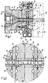
- the main extrusion head consists of a die part 12 which is penetrated by a hollow mandrel part 13, which extends beyond the end of the die part 12.
- the existing between the inside of the die part 12 and the outside of the mandrel part 13, conical and tapered in terms of "wall thickness" jacket gap 14 is supplied by the upstream screw press in the direction of arrow 15 plasticized plastic material, which then the die part 12 as the projecting section 18 of Hollow profile surrounding the mandrel part 13 in the present case as a tube with an outer diameter that corresponds to the inner diameter of the outlet opening 17 of the die part, while its inner diameter corresponds to the outer diameter of the cylindrical end section 18 of the mandrel part 13.
- the cavity 16 in the mandrel part 13 can serve to guide a cooling liquid.
- the extrusion head 11 Immediately to the main extrusion head 10 is an inventive extrusion head 11, with which several layers of further plastic materials are directly extruded onto the outside of the extrudate of the main extrusion head 10.
- the extrusion head 11 has a plurality of feed elements 20, 21, 22, 23 (see also FIG. 2).
- Each of the feed elements 20-23 is paired with a closely fitting disc 24, 25, here the feed elements 20, 21 are paired with the disc 24 and the feed elements 22, 23 are paired with the disc 25.
- the feed element 20 has a central passage 26, the inside diameter of which corresponds exactly to the inside diameter of the outlet opening 17 and is designated d 1 in FIG. 2.
- d 1 the inside diameter of the outlet opening 17
- centering surfaces are formed both on the feed element 20 and on the end face of the die part 12, for example on the feed element 20 an annular rib 27 which engages in a shoulder 29 on the end face.
- a circular recess 30 or 31 is formed on their sides facing each other, the depth of which is less than half the thickness of the disk 24 clamped between the feed elements 20 and 21. to center the circular disk 24, which has a central aperture 32 (FIG. 2), coaxially with respect to the passage 20.
- the recess 31 serves to center the feed element 21, which also has a central passage 33 (FIG. 2), with respect to the disk 24 and thus also with respect to the feed element 20.
- the feed elements 22, 23, which are only indicated with their outlines in FIG. 1, are mounted on the feed element 21 with the intermediate scraper 25. It remains to be added that the feed element 21 is clamped to the feed element 20 by means of bolts 28 '.
- Each of the feed elements 20-23 has an inlet connection on its circumference, only the inlet connections 34, 35 of the feed elements 20 and 21 being shown in solid lines in FIG. 1.
- the outlet of a further extruder, not shown, is connected to each of these inlet connections and feeds a further, plasticized plastic material to the relevant inlet connection.
- the feed elements can be arranged with inlet connections offset in the circumferential direction. Accordingly, the connecting pieces of the auxiliary extruders supplying the feed elements can be offset from one another.
- two channel sections 36, 37 extend from the inner end of the inlet connection 24 in opposite directions, at the ends of which two further channel sections 38, 39 and 40, 41 each connect in opposite directions .
- channel sections 36-41 have the shape of an arcuate groove with (see FIG. 1) essentially a semicircular cross section, the passage cross section of the channel sections 36,37 being larger than that of the channel sections 38-41.
- the channel sections 38-41 open out at locations which have a circumferential distance of 90 ° from one another into a self-contained circumferential groove 42, which over its entire circumference has an annular gap 43 (between the flat disk 24 and the side of the feed element 20 facing it) ( Fig. 1,2) is connected.
- This annular gap 43 opens into the transition point between the passage 26 of the feed element 20 and the diaphragm opening 32 of the disk 24.
- This diaphragm opening 32 has an inner diameter denoted by d 2 in FIG d 1 resulting extrudate extruded layer is greater than d 1 .
- the aperture 32 thus also serves as a calibration opening.
- the side of the feed element 21 facing the disk 24 carries a feed channel starting from the inlet connection 35, which has the same design as the feed channel of the feed element 20 described with reference to FIG. 3, which is why a description of the same is unnecessary at this point.
- the feed channel of the feed element 21 ends in an annular gap 44 (FIG. 2) which is open towards the passage 33.
- This passage 33 has an inner diameter denoted by d 3 , which is greater than d 2 by twice the layer thickness of the material layer extruded through the feed element 21.
- the central passage in the feed element 22 is designated 45 and also has the diameter d 3 .
- the feed channel formed on the side of the feed element 22 facing the disk 25 is again of the same design as described with reference to FIG. 3. This in turn opens into an annular gap 47 formed with the flat side of the disk 25 and open to the passage 45 and to the aperture opening 46 of the disk 45, through which an additional layer is extruded onto the already existing two extruded layers.
- the aperture 46 therefore has an inner diameter denoted by d 4 , which is greater than d 3 by twice the layer thickness of the layer extruded through the annular gap 47.
- the feed element 23 carries on its side facing the disk 25 a feed channel which is of the same design as described with reference to FIG. 3. It opens into an annular gap 49 that is open toward the aperture 46 of the disk 25 and towards the passage 48 in the feed element 23.
- the passage 48 has an internal diameter denoted by d 5 , which is twice the layer thickness of the layer extruded through the annular gap 49 than d 4 .
- the extrusion head described not only has a very simple structure, but can also be converted with a minimum of effort for other dimensions of the layers to be extruded.
- all the feed elements, with the exception of their central passages, have the same dimensions. The same applies to the disks.
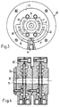
- FIG. 4 shows a longitudinal section through the extrusion head described in its design for extruding four plastic layers onto an already existing round profile, for example onto a plastic tube.
- the construction of the embodiment of FIG. 4 is identical to that of FIG. 1, with the exception that this does not directly connect to a main extrusion head, but instead is provided with a coaxial inlet aperture 50 with an aperture opening 51, the inside diameter of which is the same as the inside diameter of the central passage 26 'in the adjoining feed element 20'.
Landscapes
- Engineering & Computer Science (AREA)
- Mechanical Engineering (AREA)
- Manufacturing & Machinery (AREA)
- Extrusion Moulding Of Plastics Or The Like (AREA)
Description
- Die vorliegende Erfindung betrifft einen Extrudierkopf zur Herstellung mehrschichtiger Profile, insbesondere Hohlprofile.
- Ein Extrudierkopf zur Herstellung von zweischichtigen Profilen, insbesondere Hohlprofilen, mit einem eine Ringdüse bildenden Element, die in einer zur Extrusionsrichtung rechtwinkligen Ebene liegt, ist bekannt (offenkundige Vorbenutzung Reifenhäuser GmbH & Co. Maschinenfabrik, D-53839 Troisdorf). Bei dem bekannten Extrudierkopf ist die Ringdüse durch ein mit einem dicht anliegenden, eine Blendenöffnung aufweisenden Einsatzring gepaartes Speiseelement gebildet. Das Speiseelement weist einen zur Blendenöffnung koaxialen Durchlass auf und ist mit einem an seinem Umfang ausgebildeten Einlassstutzen versehen. Dieser ist über einen mehrfach verzweigten Zuführkanal mit der Ringdüse verbunden.
- Weitere Bekannte Extrudierköpfe sind beispielsweise in der GB-A-1 125 742 beschrieben, sie sind aus mehreren, trichterförmigen, mit radialem Abstand ineinander angeordneten Elementen aufgebaut, wobei die Innenwand des einen Elementes mit der Aussenwand des darin angeordneten Elementes einen zur Düsenöffnung hin sich verjüngenden Mantelspalt bilden. Alle diese Elemente enden an ihrer engsten Stelle in einer Ringdüse, die in einer zur Extrusionsrichtung im wesentlichen rechtwinkligen Ebene angeordnet ist. Solche Extrudierköpfe sind verhältnismässig teuer. Die Dicke der einzelnen, zu extrudierenden Schicht ist durch die Differenz zwischen dem Innendurchmesser am Ende des einen Elementes und dem Aussendurchmesser am Ende des darin angeordneten Elementes gegeben. Eine Veränderung der Dicke der zu extrudierenden Schicht kann nur in beschränktem Masse durch axiale Verstellung der trichterförmigen Elemente inbezug aufeinander erzielt werden. Ausserdem bedarf es besonderer Vorkehrungen, um mit den bekannten Extrudierköpfen Beschichtungen direkt auf ein Grundextrudat zu extrudieren. Schliesslich ist es mit den bekannten Extrudierköpfen nur möglich, eine vergleichsweise geringe Anzahl von Schichten gleichzeitig zu extrudieren. Bei Montagearbeiten werden die Einzelelemente leicht beschädigt; ausserdem ist die Montage umständlich und zeitraubend. Als Folge dieser Nachteile werden Grundprofil und darüberliegende Schichten in Einzelextrudern hergestellt, wobei zwischen den einzelnen Extrusionen das Hohlprofil abgekühlt und erwärmt werden muss.
- Der Erfindung liegt das Problem zugrunde, den Extrudierkopf der eingangs beschriebenen Art derart weiterzubilden dass bei, einfachem Aufbau mehrere schichten aufgetragen werden können. Diesen Zweck erfüllt der vorgeschlagene Extrudierkopf dadurch, dass er die im Patentanspruch 1 umschriebenen Merkmale aufweist.
- Bevorzugte Ausführungsformen sind in den abhängigen Ansprüchen umschrieben.
- Nachstehend sind rein beispielsweise Ausführungsformen des vorgeschlagenen Extrudierkopfes anhand der Zeichnung näher beschrieben. Es zeigt:
- Fig. 1
- einen direkt an einen Hauptextrudierkopf für ein Hohlprofil angeschlossenen Extrudierkopf im Längsschnitt;
- Fig. 2
- in vergrössertem Massstab das mit dem Kreis II in Fig. 1 umrahmte Detail;
- Fig. 3
- eine Ansicht, teilweise im Schnitt eines der Speiseelemente der Fig. 1 in der Ebene III-III und von rechts her gesehen; und
- Fig. 4
- eine Ausführungsvariante zum Aufextrudieren von vier Schichten auf ein vorhandenes Rundprofil.
- In Fig. 1 erkennt man einen an eine nicht dargestellte Schneckenpresse angeschlossenen Haupt-Extrudierkopf 10, an den unmittelbarein Extrudierkopf 11 gemäss der Erfindung angeschlossen ist. Der Haupt-Extrudierkopf besteht aus einem Matrizenteil 12, der von einem hohlen Dornteil 13 durchsetzt ist, wobei dieser sich über das Ende des Matrizenteiles 12 hinaus erstreckt. Dem zwischen der Innenseite des Matrizenteiles 12 und der Aussenseite des Dornteiles 13 vorhandenen, kegelförmigen und bezüglich "Wandstärke" sich verjüngenden Mantelspalt 14 wird durch die vorgeschaltete Schneckenpresse in Richtung des Pfeiles 15 plastifiziertes Kunststoffmaterial zugeführt, das dann den Matrizenteil 12 als den vorstehenden Abschnitt 18 des Dornteiles 13 umgebendes Hohlprofil im vorliegenden Falle als Rohr- mit einem Aussendurchmesser verlässt, der dem Innendurchmesser der Austrittsöffnung 17 des Matrizenteiles entspricht, wahrend dessen Innendurchmesser dem Aussendurchmesser des zylindrischen Endabschnittes 18 des Dornteiles 13 entspricht. Der Hohlraum 16 im Dornteil 13 kann zur Führung einer Kühlflüssigkeit dienen.
- Unmittelbar an den Hauptextrudierkopf 10 schliesst ein erfindungsgemässer Ertrudierkopf 11 an, mit welchem auf die Aussenseite des Extrudates des Hauptextrusionskopfes 10 mehrere Schichten aus weiteren Kunststoffmaterialien di rekt aufextrudiert werden. Zu diesem Zweck besitzt der Extrudierkopf 11 mehrere Speiseelemente 20,21,22,23 (vergleiche auch Fig. 2). Jedes der Speiseelemente 20-23 ist mit einer dicht anliegenden Scheibe 24,25 gepaart, wobei hier die Speiseelemente 20,21 gemeinsam mit der Scheibe 24 und die Speiseelemente 22,23 gemeinsam mit der Scheibe 25 gepaart sind.
- Das Speiseelement 20 weist einen zentralen Durchlass 26 auf, dessen Innendurchmesser exakt dem Innendurchmesser der Austrittsöffnung 17 entspricht und in Fig. 2 mit d1 bezeichnet ist. Um die Koaxialität des Durchlasses 26 des mittels Bolzen 28 an der ebenen endseitigen Stirnseite des Matrizenteiles 12 dicht festgeschraubten Speiselementes 20 mit der Austrittsöffnung 17 zu gewährleisten, sind sowohl am Speiseelement 20 als auch an der endseitigen Stirnseite des Matrizenteils 12 Zentrierflächen ausgebildet, beispielsweise am Speiseelement 20 eine Ringrippe 27, die in eine Absetzung 29 an der endseitigen Stirnseite eingreift.
- Sowohl im Speiseelement 20 als auch im Speiseelement 21 ist auf ihren einander zugekehrten Seiten eine kreisrunde Vertiefung 30 bzw. 31 ausgebildet, deren Tiefe je geringer ist als die halbe Dicke der zwischen den Speiseelementen 20 und 21 festgeklemmten Scheibe 24. Die Vertiefung 30 dient dazu, die kreisrunde Scheibe 24, die eine zentrale Blendenöffnung 32 (Fig. 2) aufweist, inbezug auf den Durchlass 20 koaxial zu zentrieren. Die Vertiefung 31 dient dazu, das Speiseelement 21, das ebenfalls einen zentralen Durchlass 33 (Fig. 2) aufweist, bezüglich der Scheibe 24 und damit auch bezüglich des Speiseelementes 20 zu zentrieren. Analog sind die in Fig. 1 nur mit ihren Umrissen angedeuteten Speiseelemente 22,23 mit der dazwischenliegenden Schelbe 25 an dem Speiseelement 21 montiert. Nachzutragen bleibt, dass das Speiseelement 21 mit dem Speiseelement 20 mittels Bolzen 28' verspannt ist.
- Jedes der Speiseelemente 20-23 besitzt an seinem Umfang einen Einlassstutzen, wobei in Fig. 1 nur die Einlassstutzen 34,35 der Speiseelemente 20 bzw. 21 in ausgezogenen Linien dargestellt sind. An jeden dieser Einlassstutzen ist der Auslass eines nicht dargestellten weiteren Extruders angeschlossen, das dem betreffenden Einlassstutzen ein weiteres, plastifiziertes Kunststoffmaterial zuführt. Die Speiseelemente können mit in Umfangsrichtung versetzten Einlassstutzen angeordnet sein. Entsprechend können die Anschlussstutzen der die Speiseelemente beliefernden Hilfsextruder gegeneinander versetzt sein. Wie der Fig. 3 am Beispiel des Speiseelementes 20 zu entnehmen ist, gehen vom inneren Ende des Einlassstutzens 24 in entgegengesetzten Richtungen zwei Kanalabschnitte 36,37 aus, an deren Enden nochmals in entgegengesetzten Richtungen je zwei weitere Kanalabschnitte 38,39 und 40,41 anschliessen. Diese Kanalabschnitte 36-41 haben die Form einer kreisbogenförmigen Nut mit (siehe Fig. 1) im wesentlichen einem halbkreisförmigen Querschnitt, wobei der Durchlassquerschnitt der Kanalabschnitte 36,37 grösser als jener der Kanalabschnitte 38-41 ist. Die Kanalabschnitte 38-41 münden an Stellen, die voneinander einen Umfangsabstand von 90° haben, in eine in sich geschlossene Umfangsnut 42, die über ihren gesamten Umfang mit einem zwischen der ebenen Scheibe 24 und der ihr zugekehrten Seite des Speiseelementes 20 vorhandenen Ringspalt 43 (Fig. 1,2) in Verbindung steht. Dieser Ringspalt 43 mündet in die Übergangsstelle zwischen dem Durchlass 26 des Speiseelementes 20 und der Blendenöffnung 32 der Scheibe 24. Diese Blendenöffnung 32 hateinen mit d2 in Fig. 2 bezeichneten Innendurchmesser, der um die doppelte Schichtdicke derdurch den Ringspalt 43 auf das mit dem Aussendurchmesser d1 anfallende Extrudat aufextrudierte Schicht grösser als d1 ist. Die Blendenöffnung 32 dient somit auch als Kalibrieröffnung.
- Die der Scheibe 24 zugekehrte Seite des Speiseelementes 21 trägt einen vom Einlassstutzen 35 ausgehenden Zuführkanal, der gleich ausgebildet ist, wie der anhand Fig. 3 beschriebene Zuführkanal des Speiselementes 20, weshalb sich eine Beschreibung desselben an dieser Stelle erübrigt. Der Zuführkanal des Speiselementes 21 endet in einem Ringspalt 44 (Fig. 2), der zum Durchlass 33 hin offen ist. Dieser Durchlass 33 hat einen mit d3 bezeichneten Innendurchmesser, der um die doppelte Schichtdicke der durch das Speiseelement 21 aufextrudierten Stoffschicht grösser ist als d2.
- Der zentrale Durchlass im Speiseelement 22 ist mit 45 bezeichnet und besitzt ebenfalls den Durchmesser d3. Der an der der Scheibe 25 zugekehrten Seite des Speiseelementes 22 ausgebildete Zuführkanal ist wiederum gleich ausgebildet, wie anhand der Fig. 3 beschrieben. Dieser mündetwiederum in einen mitderflachen Seite der Scheibe 25 gebildeten, zum Durchlass 45 und zur Blendenöffnung 46 der Scheibe 45 hin offenen Ringspalt 47, durch den eine weitere Schicht auf die bereits vorhandenen zwei aufextrudierten Schichten aufextrudiert wird. Die Blendenöffnung 46 hat daher einen mit d4 bzeichneten Innendurchmesser, der um das Doppelte der Schichtdicke der durch den Ringspalt 47 aufextrudierten Schicht grösser ist als d3.
- Das Speiseelement 23 trägt auf seiner der Scheibe 25 zugekehrten Seite einen Zuführkanal, der gleich ausgebildet ist wie anhand der Fig. 3 beschrieben. Er mündet in einen zur Blendenöffnung 46 der Scheibe 25 und zum Durchlass 48 im Speiseelement 23 hin offenen Ringspalt 49. Der Durchlass 48 hat einen mit d5 bezeichneten Innendurchmesser, der um die doppelte Schichtdicke der durch den Ringspalt 49 aufextrudierten Schicht grösser ist als d4.
- Aus dem gesagten ergibt sich, dass der beschriebene Extrudierkopf nicht nur einen sehr einfachen Aufbau aufweist, sondern auch mit einem Mindestaufwand für andere Abmessungen der zu extrudierenden Schichten umrüstbar ist. In der Tat besitzen alle Speiselemente mit Ausnahme Ihrer zentralen Durchlässe die gleichen Abmessungen. Das gleiche gilt für die Scheiben.
- In der Fig. 4 ist ein Längsschnitt durch den beschriebenen Extrudierkopf in seiner Ausbildung zum Aufextrudieren von vier Kunststoffschichten auf ein bereits vorhandenes Rundprofil, beispielsweise auf ein Kunststoffrohr, gezeigt. Der Aufbau der Ausführungsform der Fig. 4 ist identisch zu jenem der Fig. 1, mit Ausnahme, dass diese nicht unmittelbaran einen Hauptextrusionskopf anschliesst, sondern an dessen Stelle mit einer koaxialen Eingangsblende 50 mit einer Blendenöffnung 51 versehen ist, deren Innendurchmesser gleich wie der Innendurchmesser des zentralen Durchlasses 26' im daran anschliessenden Speiseelement 20' ist.
- Obwohl hier die Erfindung mit einem mehrschichtigen Rohr veranschaulicht wurde, eignet sie sich ebenso zur Herstellung anderer mehrschichtiger Hohlprofile.
Claims (10)
- Extrudierkopf zum Herstellen mehrschichtiger Profile, insbesondere Hohlprofile, der dazu bestimmt ist, einem Hauptextrudierkopf (10) für ein Grundprofil nachgeschaltet zu sein und auf die Aussenseite des Grundprofils mehrere Schichten aufzutragen, mit je Schicht einer in einer zur Extrusionsrichtung im wesentlichen rechtwinkligen Ebene liegenden Ringdüse (43,44,47,49), die durch ein mit einer dicht anliegenden, eine Blendenöffnung (32,46) aufweisenden Scheibe (24,25) gepaartes Speiseelement (20,21,22,23) gebildet ist, das einen zur Blendenöffnung (32,46) koaxialen Durchlass (26,33,45,48) aufweist, und das mit einem an seinem Umfang ausgebildeten Einlassstutzen (34,35) versehen ist, der über einen mehrfach verzweigten, in Richtung zur Scheibe hin offenen Zuführkanal (36,37,38,39,40,41,42) mit der Ringdüse (43,44,47,49) verbunden ist, wobei zwei beidseitig gegen eine Scheibe (24,25) anliegende Speiseelemente (20,21,22,23) beidseits der Scheibe (24,25) mit dieser zwei Ringdüsen (43,44,47,49) bilden und die Durchlässe (26,33,45,48) der Speiseelemente (20,21,22,23) und die Blendenöffnung (32,46) der Scheibe (24,25) zwecks Bildung übereinander liegender Schichten unterschiedlich gross sind.
- Extrudierkopf nach Patentanspruch 1, dadurch gekennzeichnet, dass die zwei Speiseelemente (20,21;22,23) mittels Schrauben (28') gegeneinander verspannt sind und die Scheibe (24;25) zwischen sich festklemmen.
- Extrudierkopf nach Patentansprüch 1 oder 2, dadurch gekennzeichnet, dass der Zuführkanal zwei vom Einlassstutzen (34,35) in entgegengesetzten Richtungen ausgehende Kanalabschnitte (36,37) aufweist, von deren Enden je zwei weitere Kanalabschnitte (38,39,40,41) in entgegengesetzten Richtungen ausgehen, die ihrerseits in einen den Durchlass (26,33,45,48) des Speiseelementes (20,21,22,23) umgebenden Ringspalt (43,44,47,49) einmünden, der die Ringdüse bildet.
- Extrudierkopf nach Patentanspruch 3, dadurch gekennzeichnet, dass die weiteren Kanalabschnitte (38,39; 40,41) in gleichmässigen Umfangsabständen in den Ringspalt (43,44,47,49) einmünden.
- Extrudierkopt nach Patentanspruch 2 oder 3, dadurch gekennzeichnet, dass die Kanalabschnitte (36-41) einen zum Durchlass (28,33,45,48) des Speiseelementes (20-23) koaxialen, kreisbogenförmigen Verlauf aufweisen.
- Extrudierkopf nach einem der Patentansprüche 3-5, dadurch gekennzeichnet, dass die Kanalabschnitt (36-41) einen im wesentlichen halbkreisförmigen Querschnitt aufweisen.
- Extrudierkopf nach einem der Patentsprüche 3-6, dadurch gekennzeichnet, dass die zuerst genannten Kanalabschnitte (36,37) einen grösseren Durchflussquerschnitt als die weiteren Kanalabschnitte (38-41) aufweisen.
- Extrudierkopf nach Patentanspruch 2, dadurch gekennzeichnet, dass die der Scheibe (24,25) abgekehrten Seiten der beiden Speiseelemente (20,21:22,23) mit gegengleich geformten, zum Durchlass (26,33,45,48) koaxialen Zentrierflächen (27,29), versehen sind.
- Extrudierkopf nach Patentanspruch 2, dadurch gekennzeichnet, dass die Scheibe (24,25) kreisrund ist und die beiden Speiseelemente (20,21:22,23) auf ihrer der Scheibe (24,25) zugekehrten Seite eine kreisrunde Vertiefung (30,31) aufweisen, deren Innendurchmesser dem Aussendurchmesser der Scheibe (24,25) entspricht und deren Tiefe geringer als die halbe Dicke der Scheibe (24,25) ist.
- Extrudierkopf nach einem der vorangehenden Ansprüche, dadurch gekennzeichnet, dass er mit dem Hauptextrudierkopf (10) verbunden ist.
Priority Applications (1)
| Application Number | Priority Date | Filing Date | Title |
|---|---|---|---|
| AT90117807T ATE92839T1 (de) | 1989-09-26 | 1990-09-15 | Extrudierkopf zum herstellen mehrschichtiger extrudate. |
Applications Claiming Priority (2)
| Application Number | Priority Date | Filing Date | Title |
|---|---|---|---|
| CH348689 | 1989-09-26 | ||
| CH3486/89 | 1989-09-26 |
Publications (3)
| Publication Number | Publication Date |
|---|---|
| EP0419983A1 EP0419983A1 (de) | 1991-04-03 |
| EP0419983B1 EP0419983B1 (de) | 1993-08-11 |
| EP0419983B2 true EP0419983B2 (de) | 1996-07-17 |
Family
ID=4257032
Family Applications (1)
| Application Number | Title | Priority Date | Filing Date |
|---|---|---|---|
| EP90117807A Expired - Lifetime EP0419983B2 (de) | 1989-09-26 | 1990-09-15 | Extrudierkopf zum Herstellen mehrschichtiger Extrudate |
Country Status (3)
| Country | Link |
|---|---|
| EP (1) | EP0419983B2 (de) |
| AT (1) | ATE92839T1 (de) |
| DE (1) | DE59002295D1 (de) |
Families Citing this family (5)
| Publication number | Priority date | Publication date | Assignee | Title |
|---|---|---|---|---|
| US5672303A (en) * | 1992-10-17 | 1997-09-30 | Bellaform Extrusionstechnik Gmbh | Process and extruding head for the manufacture and/or coating of extruding profiles |
| DE4235101C2 (de) * | 1992-10-17 | 1994-11-10 | Krupp Bellaform Maschbau | Verfahren und Spritzkopf zum Herstellen und/oder Umhüllen von Strangprofilen |
| US6190152B1 (en) | 1996-08-26 | 2001-02-20 | Addex, Inc. | Regular division of molten extrusion flow |
| DE19835189C2 (de) | 1998-08-04 | 2001-02-08 | Unicor Rohrsysteme Gmbh | Vorrichtung zur kontinuierlichen Herstellung von nahtlosen Kunststoffrohren |
| US6343919B1 (en) * | 2000-02-28 | 2002-02-05 | Ricardo Pablo Rodriguez | Modular plastics extrusion die |
Family Cites Families (6)
| Publication number | Priority date | Publication date | Assignee | Title |
|---|---|---|---|---|
| CH315684A (it) * | 1952-10-08 | 1956-08-31 | Lavorazione Mat Plastiche Sas | Rivestimento protettivo per tubi metallici, procedimento per la sua fabbricazione ed apparecchio per l'attuazione di questo procedimento |
| US3417432A (en) * | 1965-08-27 | 1968-12-24 | Brockway Glass Co Inc | Apparatus for extruding composite blow molding parisons |
| FR1589770A (de) * | 1968-10-21 | 1970-04-06 | ||
| DE2031890A1 (de) * | 1969-06-30 | 1971-01-28 | Joseph Lucas (Industries) Ltd . Birmingham (Großbritannien) | Verfahren zur Herstellung eines mehrwandigen Hohlkörpers |
| CH565031A5 (de) * | 1972-09-22 | 1975-08-15 | Dynamit Nobel Ag | |
| US4806289A (en) * | 1987-01-16 | 1989-02-21 | The Dow Chemical Company | Method of making a hollow light pipe |
-
1990
- 1990-09-15 EP EP90117807A patent/EP0419983B2/de not_active Expired - Lifetime
- 1990-09-15 DE DE9090117807T patent/DE59002295D1/de not_active Expired - Fee Related
- 1990-09-15 AT AT90117807T patent/ATE92839T1/de not_active IP Right Cessation
Also Published As
| Publication number | Publication date |
|---|---|
| EP0419983A1 (de) | 1991-04-03 |
| ATE92839T1 (de) | 1993-08-15 |
| DE59002295D1 (de) | 1993-09-16 |
| EP0419983B1 (de) | 1993-08-11 |
Similar Documents
| Publication | Publication Date | Title |
|---|---|---|
| EP1116569B1 (de) | Extruderdüsenkopf | |
| EP0215337B1 (de) | Extrusionskopf | |
| DE60130122T2 (de) | Rohrförmige mehrschichtige folien sowie verfahren und vorrichtung zu ihrer herstellung | |
| EP0494273B1 (de) | Speicherkopf für eine blasformmaschine | |
| DE1276906B (de) | Spritzkopf | |
| DE2510127A1 (de) | Strangpresskopf zum herstellen eines aus zwei konzentrischen, mit ihren schweissnaehten zueinander versetzten schichten bestehenden hohlstranges aus thermoplastischem werkstoff | |
| DE19535749C1 (de) | Extrusionskopf zur Herstellung von schlauch- oder rohrförmigen Vorformlingen aus extrudierbarem Kunststoff | |
| EP0250828B1 (de) | Extruderanlage zum Ummanteln eines strangförmigen Produktes, insbesondere eines Kabels | |
| EP1055504A1 (de) | Extruderdüsenkopf | |
| EP0419983B2 (de) | Extrudierkopf zum Herstellen mehrschichtiger Extrudate | |
| EP0349872A1 (de) | Verfahren und Vorrichtung zum Herstellen von Hohlkörpern aus thermoplastischen Kunstoffen | |
| DE1660169A1 (de) | Spinnduese und Verfahren zur Herstellung eines Spinnkanals einer Spinnduese | |
| DE19941160A1 (de) | Zylinder für einen Schneckenextruder mit Kanälen für ein Temperiermedium | |
| DE2006941A1 (en) | Plasticising extruder perforated disc | |
| EP3479993B1 (de) | Ringverteiler für einen extrusionskopf zur herstellung eines schlauchförmigen formlings aus thermoplastischem kunststoff | |
| EP1426163A2 (de) | Werkzeug zur Extrusion eines rohrförmigen Schmelzestranges | |
| DE3921631C2 (de) | ||
| DE4235101C2 (de) | Verfahren und Spritzkopf zum Herstellen und/oder Umhüllen von Strangprofilen | |
| AT325800B (de) | Strangpressanlage zur herstellung mehrfarbiger kunststoffröhrchen | |
| DE2710565A1 (de) | Spritzwerkzeug zum extrudieren von hohlen rohrelementen aus kunststoff und mit den rohrelementen erzielter behaelter | |
| EP0406226B1 (de) | Wendelkopfverteiler für eine Kunststoff-Extrusionseinrichtung | |
| DE1704861A1 (de) | Strangpresse zur Herstellung einer Mehrzahl von aufeinanderkaschierten rohrfoermigen Kunststoffschichten | |
| DE69018094T2 (de) | Schmiersystem für kunststoffextruder. | |
| DE2839967C2 (de) | ||
| DE102017107563A1 (de) | Mehrschichtwerkzeug |
Legal Events
| Date | Code | Title | Description |
|---|---|---|---|
| PUAI | Public reference made under article 153(3) epc to a published international application that has entered the european phase |
Free format text: ORIGINAL CODE: 0009012 |
|
| AK | Designated contracting states |
Kind code of ref document: A1 Designated state(s): AT CH DE FR GB IT LI |
|
| 17P | Request for examination filed |
Effective date: 19910506 |
|
| 17Q | First examination report despatched |
Effective date: 19920522 |
|
| GRAA | (expected) grant |
Free format text: ORIGINAL CODE: 0009210 |
|
| ITF | It: translation for a ep patent filed | ||
| AK | Designated contracting states |
Kind code of ref document: B1 Designated state(s): AT CH DE FR GB IT LI |
|
| REF | Corresponds to: |
Ref document number: 92839 Country of ref document: AT Date of ref document: 19930815 Kind code of ref document: T |
|
| GBT | Gb: translation of ep patent filed (gb section 77(6)(a)/1977) |
Effective date: 19930811 |
|
| REF | Corresponds to: |
Ref document number: 59002295 Country of ref document: DE Date of ref document: 19930916 |
|
| ET | Fr: translation filed | ||
| PLBI | Opposition filed |
Free format text: ORIGINAL CODE: 0009260 |
|
| PLAB | Opposition data, opponent's data or that of the opponent's representative modified |
Free format text: ORIGINAL CODE: 0009299OPPO |
|
| 26 | Opposition filed |
Opponent name: REIFENHAEUSER GMBH & CO. MASCHINENFABRIK Effective date: 19940511 |
|
| R26 | Opposition filed (corrected) |
Opponent name: REIFENHAEUSER GMBH & CO. MASCHINENFABRIK Effective date: 19940510 |
|
| PLAW | Interlocutory decision in opposition |
Free format text: ORIGINAL CODE: EPIDOS IDOP |
|
| PUAH | Patent maintained in amended form |
Free format text: ORIGINAL CODE: 0009272 |
|
| STAA | Information on the status of an ep patent application or granted ep patent |
Free format text: STATUS: PATENT MAINTAINED AS AMENDED |
|
| ITF | It: translation for a ep patent filed | ||
| 27A | Patent maintained in amended form |
Effective date: 19960717 |
|
| AK | Designated contracting states |
Kind code of ref document: B2 Designated state(s): AT CH DE FR GB IT LI |
|
| REG | Reference to a national code |
Ref country code: CH Ref legal event code: AEN Free format text: AUFRECHTERHALTUNG DES PATENTES IN GEAENDERTER FORM |
|
| PGFP | Annual fee paid to national office [announced via postgrant information from national office to epo] |
Ref country code: GB Payment date: 19960816 Year of fee payment: 7 |
|
| PGFP | Annual fee paid to national office [announced via postgrant information from national office to epo] |
Ref country code: DE Payment date: 19960821 Year of fee payment: 7 Ref country code: AT Payment date: 19960821 Year of fee payment: 7 |
|
| PGFP | Annual fee paid to national office [announced via postgrant information from national office to epo] |
Ref country code: FR Payment date: 19960827 Year of fee payment: 7 |
|
| GBTA | Gb: translation of amended ep patent filed (gb section 77(6)(b)/1977) |
Effective date: 19960814 |
|
| PGFP | Annual fee paid to national office [announced via postgrant information from national office to epo] |
Ref country code: CH Payment date: 19960925 Year of fee payment: 7 |
|
| ET3 | Fr: translation filed ** decision concerning opposition | ||
| PG25 | Lapsed in a contracting state [announced via postgrant information from national office to epo] |
Ref country code: GB Free format text: LAPSE BECAUSE OF NON-PAYMENT OF DUE FEES Effective date: 19970915 Ref country code: AT Free format text: LAPSE BECAUSE OF NON-PAYMENT OF DUE FEES Effective date: 19970915 |
|
| PG25 | Lapsed in a contracting state [announced via postgrant information from national office to epo] |
Ref country code: LI Free format text: LAPSE BECAUSE OF NON-PAYMENT OF DUE FEES Effective date: 19970930 Ref country code: FR Free format text: THE PATENT HAS BEEN ANNULLED BY A DECISION OF A NATIONAL AUTHORITY Effective date: 19970930 Ref country code: CH Free format text: LAPSE BECAUSE OF NON-PAYMENT OF DUE FEES Effective date: 19970930 |
|
| GBPC | Gb: european patent ceased through non-payment of renewal fee |
Effective date: 19970915 |
|
| REG | Reference to a national code |
Ref country code: CH Ref legal event code: PL |
|
| PG25 | Lapsed in a contracting state [announced via postgrant information from national office to epo] |
Ref country code: DE Free format text: LAPSE BECAUSE OF NON-PAYMENT OF DUE FEES Effective date: 19980603 |
|
| REG | Reference to a national code |
Ref country code: FR Ref legal event code: ST |
|
| PG25 | Lapsed in a contracting state [announced via postgrant information from national office to epo] |
Ref country code: IT Free format text: LAPSE BECAUSE OF NON-PAYMENT OF DUE FEES;WARNING: LAPSES OF ITALIAN PATENTS WITH EFFECTIVE DATE BEFORE 2007 MAY HAVE OCCURRED AT ANY TIME BEFORE 2007. THE CORRECT EFFECTIVE DATE MAY BE DIFFERENT FROM THE ONE RECORDED. Effective date: 20050915 |