EP0419326A1 - Verfahren zum Stimulieren des auf ein statisches Tastenfeld wirkenden Fingers einer Bedienungsperson und Vorrichtung zur Durchführung des Verfahrens - Google Patents
Verfahren zum Stimulieren des auf ein statisches Tastenfeld wirkenden Fingers einer Bedienungsperson und Vorrichtung zur Durchführung des Verfahrens Download PDFInfo
- Publication number
- EP0419326A1 EP0419326A1 EP90402521A EP90402521A EP0419326A1 EP 0419326 A1 EP0419326 A1 EP 0419326A1 EP 90402521 A EP90402521 A EP 90402521A EP 90402521 A EP90402521 A EP 90402521A EP 0419326 A1 EP0419326 A1 EP 0419326A1
- Authority
- EP
- European Patent Office
- Prior art keywords
- keyboard
- movable
- key
- movement
- finger
- Prior art date
- Legal status (The legal status is an assumption and is not a legal conclusion. Google has not performed a legal analysis and makes no representation as to the accuracy of the status listed.)
- Granted
Links
- 238000000034 method Methods 0.000 title claims abstract description 20
- 230000003068 static effect Effects 0.000 title claims description 9
- 230000008569 process Effects 0.000 title abstract description 5
- 238000006073 displacement reaction Methods 0.000 claims abstract description 9
- 238000004804 winding Methods 0.000 claims description 16
- 238000001514 detection method Methods 0.000 claims description 11
- 230000000694 effects Effects 0.000 claims description 9
- 230000008859 change Effects 0.000 claims description 8
- 230000005540 biological transmission Effects 0.000 claims description 4
- 238000005096 rolling process Methods 0.000 claims description 3
- 230000000638 stimulation Effects 0.000 claims description 2
- 230000035807 sensation Effects 0.000 abstract description 4
- 238000009877 rendering Methods 0.000 abstract 1
- 238000003825 pressing Methods 0.000 description 5
- 230000005284 excitation Effects 0.000 description 3
- 230000006870 function Effects 0.000 description 3
- 230000001960 triggered effect Effects 0.000 description 3
- 230000009471 action Effects 0.000 description 2
- 238000010586 diagram Methods 0.000 description 2
- 230000005281 excited state Effects 0.000 description 2
- 230000035939 shock Effects 0.000 description 2
- 230000008901 benefit Effects 0.000 description 1
- 239000002775 capsule Substances 0.000 description 1
- 210000002858 crystal cell Anatomy 0.000 description 1
- 239000004973 liquid crystal related substance Substances 0.000 description 1
- 238000005259 measurement Methods 0.000 description 1
- 230000004044 response Effects 0.000 description 1
- 238000010200 validation analysis Methods 0.000 description 1
Images

Classifications
-
- H—ELECTRICITY
- H01—ELECTRIC ELEMENTS
- H01H—ELECTRIC SWITCHES; RELAYS; SELECTORS; EMERGENCY PROTECTIVE DEVICES
- H01H13/00—Switches having rectilinearly-movable operating part or parts adapted for pushing or pulling in one direction only, e.g. push-button switch
- H01H13/70—Switches having rectilinearly-movable operating part or parts adapted for pushing or pulling in one direction only, e.g. push-button switch having a plurality of operating members associated with different sets of contacts, e.g. keyboard
- H01H13/84—Switches having rectilinearly-movable operating part or parts adapted for pushing or pulling in one direction only, e.g. push-button switch having a plurality of operating members associated with different sets of contacts, e.g. keyboard characterised by ergonomic functions, e.g. for miniature keyboards; characterised by operational sensory functions, e.g. sound feedback
-
- H—ELECTRICITY
- H01—ELECTRIC ELEMENTS
- H01H—ELECTRIC SWITCHES; RELAYS; SELECTORS; EMERGENCY PROTECTIVE DEVICES
- H01H2215/00—Tactile feedback
- H01H2215/05—Tactile feedback electromechanical
Definitions
- the present invention relates to a stimulation method making it possible to generate on the finger of a user who acts on a key of a static keyboard, a determined tactile effect, for example in order to recreate a feeling of effort and similar break to that provided by conventional push buttons (in particular of the type with deformable capsule).
- a static keyboard usually comprises a rigid surface possibly mounted on a force measurement system and covered with a so-called “tactile” surface making it possible to make and locate the selections.
- This keyboard can also comprise a grid for guiding the supports and for delimiting the zones constituting the keys, this grid being attached to the touch surface or integral with it.
- the invention more particularly aims to eliminate these drawbacks.
- the above threshold value may possibly be determined so that the movement of the movable part begins at the time of the change of state of the switching circuit associated with the key which is pressed, or even after a period of determined time following this change of state, for example a period necessary for the validation of said change of state.
- the method according to the invention further comprises a return of the mobile part to its initial position, either after a determined period ⁇ following the change of state, or following the release of the key by the operator.
- a device for implementing the method described above will necessarily involve: - a static type keyboard comprising a plurality of keys; - a mobile equipment including all or part of the keyboard; - Detection means able to detect at least one of the components of the stresses experienced by the keyboard following the action of an operator on a key on the keyboard; - An actuator able to generate a predetermined movement of the movable assembly; and an electronic circuit ensuring control of the actuator as a function of the signal delivered by the detector and / or of the state of the switching device associated with the key of the keyboard which has been pressed.
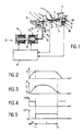
- the keyboard comprises a movable assembly 1 including a flat support 2 carrying a touch surface 3 and a grid 4 for guiding the supports and delimiting the areas serving as keys 5.
- a movable assembly 1 including a flat support 2 carrying a touch surface 3 and a grid 4 for guiding the supports and delimiting the areas serving as keys 5.
- the tactile structure could be incorporated into the support 2.
- this support 2 could possibly consist of a liquid crystal cell to ensure relegendable identification of the keys 5.
- the guide means comprise rolling elements 9, 9 ′ mounted on two respective rolling tracks 10, 11.
- the component F ⁇ (normal to the touch surface) of the forces F applied by the user to the keys is detected by means of a force detector D placed under the raceway 10.
- the movements of the mobile assembly 1 according to the double arrow 7 are controlled by an actuator module 12 constituted by a double-acting electromagnet comprising a holding winding 13, a traction winding 14, and a mobile armature 15 connected to the mobile equipment 1 via a transmission device.
- an actuator module 12 constituted by a double-acting electromagnet comprising a holding winding 13, a traction winding 14, and a mobile armature 15 connected to the mobile equipment 1 via a transmission device.
- This transmission device here comprises a link 16 whose ends are respectively articulated on said frame 15 and on said equipment 1 and whose central part is pivotally mounted around a fixed axis 17.
- the excitation of the coils 13, 14 is controlled by a computer 18 which also receives information from the selection location devices, associated with each key 5, and the detection signal from the force detector D.
- the actuator 12 could be produced using two electromagnets (EAT traction and EAM holding) mounted in tandem and having movable armatures or cores mechanically coupled to each other.
- the role of the actuator 12 is more particularly: . to keep the moving element 1 in the rest position as long as the selection is not taken into account by the computer 18 is not effective, by opposing any movement due to a force exerted by the operator's finger; . releasing the moving element 1 and moving it in the direction of the force F exerted by the operator, when the selection has been taken into account by the computer 18.
- FIGS. 2 to 5 The operation of the keyboard described above is more particularly illustrated in FIGS. 2 to 5.
- the holding winding 13 of the actuation module 12 is energized, the movable armature 15 is in the position for which the air gap formed between the fixed frame associated with the winding 13 and the movable frame 15 is minimum. The retaining force generated by this winding 13 is then maximum.
- the traction winding 14 of the module 12 is not supplied; the air gap between the fixed frame associated with this winding 14 and the movable frame 15 is maximum and corresponds to the maximum stroke of the movable frame 15.
- the operator places his finger on a key and exerts an increasing pressing force F.
- the computer 18 determines that the selection is not effective and therefore maintains the rest state.
- the force exercised exceeds a preprogrammed threshold F1 ( Figure 3) which here corresponds to the detection threshold S of the operated key ( Figure 2).
- the computer 18 determines that the selection is effective and causes the movement of the moving element 1 by cutting the supply of the holding winding 13 and by establishing the supply of the traction winding 14. It should be noted that this process could also be triggered, either in response to the exceeding of the detection threshold S (and, consequently, of the change of state of the switching circuit associated with the key 5 pressed), or when a logical combination, for example of the AND or OR type of the two trigger conditions mentioned above, is performed.
- the excitation of the traction winding 14 causes the mobile armature 15 to move until, at the end of the travel, the air gap between the fixed armature associated with the winding 14 and the mobile armature 15 be minimal.
- This displacement of the movable armature causes a corresponding displacement of the movable assembly 1 along a stroke which is equal to the product of the stroke of the movable armature 15 by a multiplication (or demultiplication) coefficient determined by the ratio of the lengths of the two arms b1, b2 of the link 16.
- the moving part 1 is then maintained in this excited state for a period ⁇ determined by the computer 18, either by programming, or by detection of an instant t2 marking the end of the period ⁇ which corresponds to the moment when the operator releases the selected key.
- This determination of the instant t2 can be ensured, either from the change of state of the switching circuits associated with the pressed key 5, or from the passage of the detected force. by detector D below a certain threshold F2 ( Figure 3).
- the computer 18 causes the traction winding 14 to become de-energized and the holding winding 13 to be excited, so that the moving element 1 returns to the rest position.
- a return spring 20 can also be provided to facilitate this return and to place the mobile assembly 1 in the rest position, in the absence of supply to the computer 18.
- Figures 6 and 7 show the similarities between the sensations obtained using a keyboard according to the invention and those obtained using a conventional button.
- the arrow f indicates the location of the stroke of the key corresponding to the taking into account of the selection.
- the movable assembly 1 moves in translation along an axis parallel to the touch surface 3, which is then preferably oriented so that the force exerted by the finger of the operator on a key 5 is oriented obliquely to said axis of movement.
- the force F has, in the plane of the tactile surface 3, a component F 'tending to bring the mobile assembly 1 to the excited state, to against the action exerted by the spring 20 and the attraction due to the excitation of the retaining winding 13. Thanks to these features, it becomes possible to suitably adjust the tactile effect generated by the keyboard on the operator's finger.
- the moving element 1 could be mounted on the fixed structure 6 as shown in FIG. 8, so that it moves in translation along an axis X perpendicular to the plane of the touch surface 3 and, preferably, parallel to the pressing force F exerted by the user's finger.
- the actuation module 12 is then designed so as to ensure the translation of the movable assembly 1 along the above-mentioned axis of movement X and according to the previously defined sequence, in order to restore the sensation of a pusher which gives way under support.
Landscapes
- Input From Keyboards Or The Like (AREA)
Applications Claiming Priority (2)
| Application Number | Priority Date | Filing Date | Title |
|---|---|---|---|
| FR8912455 | 1989-09-22 | ||
| FR8912455A FR2652445B1 (fr) | 1989-09-22 | 1989-09-22 | Procede pour la stimulation du doigt d'un operateur agissant sur un clavier statique et dispositif pour la mise en óoeuvre de ce procede. |
Publications (2)
| Publication Number | Publication Date |
|---|---|
| EP0419326A1 true EP0419326A1 (de) | 1991-03-27 |
| EP0419326B1 EP0419326B1 (de) | 1994-10-26 |
Family
ID=9385756
Family Applications (1)
| Application Number | Title | Priority Date | Filing Date |
|---|---|---|---|
| EP90402521A Expired - Lifetime EP0419326B1 (de) | 1989-09-22 | 1990-09-13 | Verfahren zum Stimulieren des auf ein statisches Tastenfeld wirkenden Fingers einer Bedienungsperson und Vorrichtung zur Durchführung des Verfahrens |
Country Status (5)
| Country | Link |
|---|---|
| US (1) | US5189390A (de) |
| EP (1) | EP0419326B1 (de) |
| DE (1) | DE69013632T2 (de) |
| ES (1) | ES2063314T3 (de) |
| FR (1) | FR2652445B1 (de) |
Cited By (5)
| Publication number | Priority date | Publication date | Assignee | Title |
|---|---|---|---|---|
| EP0518648A2 (de) * | 1991-06-10 | 1992-12-16 | Fujitsu Limited | Justierbares Tastgefühl für Tastaturen |
| WO1993005527A1 (de) * | 1991-08-28 | 1993-03-18 | Peter Ludwig | Elektrischer schalter, insbesondere drucktastenschalter |
| FR2778267A1 (fr) * | 1998-04-30 | 1999-11-05 | Otis Elevator Co | Bouton d'appel d'ascenseur pour non-voyants |
| FR2944613A1 (fr) * | 2009-04-20 | 2010-10-22 | Dav | Dispositif de commande a retour haptique |
| WO2016184728A1 (de) * | 2015-05-19 | 2016-11-24 | Trw Automotive Electronics & Components Gmbh | Schaltvorrichtung mit haptischer rückkopplung |
Families Citing this family (24)
| Publication number | Priority date | Publication date | Assignee | Title |
|---|---|---|---|---|
| US6400285B1 (en) * | 1992-10-08 | 2002-06-04 | Henry Gifford | Ergonomic keyboard |
| JP2804937B2 (ja) * | 1992-10-15 | 1998-09-30 | 矢崎総業株式会社 | システムスイッチ装置 |
| US5914705A (en) * | 1996-02-09 | 1999-06-22 | Lucent Technologies Inc. | Apparatus and method for providing detent-like tactile feedback |
| US5982304A (en) * | 1997-03-24 | 1999-11-09 | International Business Machines Corporation | Piezoelectric switch with tactile response |
| US6059575A (en) * | 1998-10-21 | 2000-05-09 | Murphy; Kevin C. | Tactile recognition input device and overlay for use with an input device |
| JP2000267785A (ja) * | 1999-03-15 | 2000-09-29 | Alps Electric Co Ltd | キーボード装置 |
| US20040183783A1 (en) * | 2003-03-19 | 2004-09-23 | International Business Machines Corp. | Method and apparatus for improved keyboard accessibility using vibrating keys |
| US7161587B2 (en) * | 2003-08-14 | 2007-01-09 | International Business Machines Corporation | Method, apparatus and computer program product for providing keyboard assistance to a software application user |
| US8760413B2 (en) * | 2009-01-08 | 2014-06-24 | Synaptics Incorporated | Tactile surface |
| US10068728B2 (en) | 2009-10-15 | 2018-09-04 | Synaptics Incorporated | Touchpad with capacitive force sensing |
| US8624839B2 (en) * | 2009-10-15 | 2014-01-07 | Synaptics Incorporated | Support-surface apparatus to impart tactile feedback |
| US20120038469A1 (en) * | 2010-08-11 | 2012-02-16 | Research In Motion Limited | Actuator assembly and electronic device including same |
| US8309870B2 (en) | 2011-01-04 | 2012-11-13 | Cody George Peterson | Leveled touchsurface with planar translational responsiveness to vertical travel |
| US8912458B2 (en) | 2011-01-04 | 2014-12-16 | Synaptics Incorporated | Touchsurface with level and planar translational travel responsiveness |
| US8847890B2 (en) | 2011-01-04 | 2014-09-30 | Synaptics Incorporated | Leveled touchsurface with planar translational responsiveness to vertical travel |
| US8735755B2 (en) | 2011-03-07 | 2014-05-27 | Synaptics Incorporated | Capacitive keyswitch technologies |
| DE102011082142A1 (de) | 2011-09-05 | 2013-03-07 | Continental Automotive Gmbh | Bedieneinrichtung |
| US9177733B2 (en) | 2012-08-06 | 2015-11-03 | Synaptics Incorporated | Touchsurface assemblies with linkages |
| US9218927B2 (en) | 2012-08-06 | 2015-12-22 | Synaptics Incorporated | Touchsurface assembly with level and planar translational responsiveness via a buckling elastic component |
| WO2014025786A1 (en) | 2012-08-06 | 2014-02-13 | Synaptics Incorporated | Touchsurface assembly utilizing magnetically enabled hinge |
| US9040851B2 (en) | 2012-08-06 | 2015-05-26 | Synaptics Incorporated | Keycap assembly with an interactive spring mechanism |
| US9384919B2 (en) | 2013-03-14 | 2016-07-05 | Synaptics Incorporated | Touchsurface assembly having key guides formed in a sheet metal component |
| US9213372B2 (en) | 2013-04-19 | 2015-12-15 | Synaptics Incorporated | Retractable keyboard keys |
| DE102014017577B4 (de) * | 2014-11-27 | 2020-04-23 | Audi Ag | Bedieneinrichtung und Verfahren zum Ansteuern von Funktionseinheiten eines Kraftfahrzeugs |
Citations (1)
| Publication number | Priority date | Publication date | Assignee | Title |
|---|---|---|---|---|
| EP0278916A2 (de) * | 1987-02-11 | 1988-08-17 | Dynalab Ag | Vorrichtung an elektronischen Tastaturen zur Quittierung der Tastenbetätigung |
Family Cites Families (2)
| Publication number | Priority date | Publication date | Assignee | Title |
|---|---|---|---|---|
| US4362408A (en) * | 1980-12-01 | 1982-12-07 | Ncr Corporation | Means for avoiding accidental actuation of a critical function key |
| EP0061595B1 (de) * | 1981-03-27 | 1985-12-18 | Siemens Nixdorf Informationssysteme Aktiengesellschaft | Informationsein- und -ausgabeeinheit für Datenverarbeitungseinrichtungen |
-
1989
- 1989-09-22 FR FR8912455A patent/FR2652445B1/fr not_active Expired - Fee Related
-
1990
- 1990-09-13 EP EP90402521A patent/EP0419326B1/de not_active Expired - Lifetime
- 1990-09-13 ES ES90402521T patent/ES2063314T3/es not_active Expired - Lifetime
- 1990-09-13 DE DE69013632T patent/DE69013632T2/de not_active Expired - Fee Related
- 1990-09-21 US US07/586,645 patent/US5189390A/en not_active Expired - Lifetime
Patent Citations (1)
| Publication number | Priority date | Publication date | Assignee | Title |
|---|---|---|---|---|
| EP0278916A2 (de) * | 1987-02-11 | 1988-08-17 | Dynalab Ag | Vorrichtung an elektronischen Tastaturen zur Quittierung der Tastenbetätigung |
Non-Patent Citations (2)
| Title |
|---|
| IBM TECHNICAL DISCLOSURE BULLETIN. vol. 13, no. 8, janvier 1971, NEW YORK US page 2215 L.S.Rogers: "Keyboard Impact Feedback" * |
| IBM TECHNICAL DISCLOSURE BULLETIN. vol. 20, no. 2, juillet 1977, NEW YORK US pages 708 - 709; J.E.Fox and R.H. Harris: "Nontactile Keyboard Auxiliaries" * |
Cited By (8)
| Publication number | Priority date | Publication date | Assignee | Title |
|---|---|---|---|---|
| EP0518648A2 (de) * | 1991-06-10 | 1992-12-16 | Fujitsu Limited | Justierbares Tastgefühl für Tastaturen |
| EP0518648A3 (en) * | 1991-06-10 | 1993-06-16 | Fujitsu Limited | Adjusting keyboard "feel" |
| US5434566A (en) * | 1991-06-10 | 1995-07-18 | Fujitsu Limited | Key touch adjusting method and device |
| WO1993005527A1 (de) * | 1991-08-28 | 1993-03-18 | Peter Ludwig | Elektrischer schalter, insbesondere drucktastenschalter |
| FR2778267A1 (fr) * | 1998-04-30 | 1999-11-05 | Otis Elevator Co | Bouton d'appel d'ascenseur pour non-voyants |
| FR2944613A1 (fr) * | 2009-04-20 | 2010-10-22 | Dav | Dispositif de commande a retour haptique |
| EP2244167A3 (de) * | 2009-04-20 | 2017-03-29 | Dav | Steuervorrichtung mit haptischer Rückmeldung |
| WO2016184728A1 (de) * | 2015-05-19 | 2016-11-24 | Trw Automotive Electronics & Components Gmbh | Schaltvorrichtung mit haptischer rückkopplung |
Also Published As
| Publication number | Publication date |
|---|---|
| US5189390A (en) | 1993-02-23 |
| FR2652445B1 (fr) | 1993-05-28 |
| FR2652445A1 (fr) | 1991-03-29 |
| DE69013632T2 (de) | 1995-03-16 |
| DE69013632D1 (de) | 1994-12-01 |
| EP0419326B1 (de) | 1994-10-26 |
| ES2063314T3 (es) | 1995-01-01 |
Similar Documents
| Publication | Publication Date | Title |
|---|---|---|
| EP0419326B1 (de) | Verfahren zum Stimulieren des auf ein statisches Tastenfeld wirkenden Fingers einer Bedienungsperson und Vorrichtung zur Durchführung des Verfahrens | |
| EP1332424B1 (de) | Vorrichtung zur verarbeitung der bewegung eines zeigers auf einem bildschirm | |
| EP0185579B1 (de) | Verfahren zur Verschiebung eines beweglichen Systems, das durch einen elektrischen Motor in einer gegebenen Bahn angetrieben wird | |
| FR3003364A1 (fr) | Procede de traitement d'un geste compose, dispositif et terminal d'utilisateur associes | |
| CH659902A5 (fr) | Lecteur mixte pour cartes a piste magnetique et/ou a puce electronique. | |
| CA2266612A1 (fr) | Dispositif pour la detection de l'ouverture d'un compteur | |
| FR2575707A1 (fr) | Dispositif de detection de changement de vitesse pour la commande d'un embrayage associe a une boite de vitesses | |
| CA2484780C (fr) | Procede d`actionnement d`un frein d`aeronef equipe d`au moins un actionneur electromecanique | |
| EP0079820B2 (de) | Schaltgerät mit Anordnungen zur Selbstunterbrechung und mit einem örtlichen Antriebsteil | |
| EP0449674A1 (de) | Miniaturschalter mit Berührungseffekt | |
| FR2910160A1 (fr) | Systeme de telecommunication tactile | |
| EP1927122A1 (de) | Einrichtung zum neutralisieren einer elektrischen schalteinheit | |
| EP2564409B1 (de) | Not-aus-vorrichtung mit sichermontierbaren schaltungsanordnungen | |
| EP1181662B1 (de) | Verfahren und gerät zur elektrischen kontaktierung einer chipkarte | |
| WO2024146994A1 (fr) | Système de saisie d'un code sur un clavier tactile adapté aux personnes malvoyantes | |
| US11016447B2 (en) | Control device equipped with a module for detecting the axial position of its rod, and timepiece comprising such a control device | |
| EP0009086B1 (de) | Halbautomatische Papiereinzugsvorrichtung an einer elektronischen Schreibmaschine | |
| CH619180A5 (de) | ||
| EP0725361B1 (de) | Steuerungsvorrichtung geeignet für den Hinweis und die Bewegung eines Objektes auf einem Bildschirm | |
| FR2585861A1 (fr) | Monnayeur electro-mecanique. | |
| FR3144882A1 (fr) | Système de saisie d’un code avec activation d’un mode adapté aux personnes malvoyantes | |
| FR2806340A1 (fr) | Dispositif d'application et de liberation automatique d'un adaptateur de meulage pour verre optique | |
| CH714266A2 (fr) | Dispositif de commande muni d'un module de détection de la position axiale de sa tige, et pièce d'horlogerie comprenant un tel dispositif de commande. | |
| FR3104629A1 (fr) | Dispositif d’accès de secours d’ouvrant de véhicule à bobine de détection de position | |
| BE394345A (de) |
Legal Events
| Date | Code | Title | Description |
|---|---|---|---|
| PUAI | Public reference made under article 153(3) epc to a published international application that has entered the european phase |
Free format text: ORIGINAL CODE: 0009012 |
|
| 17P | Request for examination filed |
Effective date: 19900918 |
|
| AK | Designated contracting states |
Kind code of ref document: A1 Designated state(s): DE ES FR GB IT SE |
|
| 17Q | First examination report despatched |
Effective date: 19940303 |
|
| GRAA | (expected) grant |
Free format text: ORIGINAL CODE: 0009210 |
|
| AK | Designated contracting states |
Kind code of ref document: B1 Designated state(s): DE ES FR GB IT SE |
|
| REF | Corresponds to: |
Ref document number: 69013632 Country of ref document: DE Date of ref document: 19941201 |
|
| ITF | It: translation for a ep patent filed | ||
| REG | Reference to a national code |
Ref country code: ES Ref legal event code: FG2A Ref document number: 2063314 Country of ref document: ES Kind code of ref document: T3 |
|
| GBT | Gb: translation of ep patent filed (gb section 77(6)(a)/1977) |
Effective date: 19941209 |
|
| EAL | Se: european patent in force in sweden |
Ref document number: 90402521.0 |
|
| PLBE | No opposition filed within time limit |
Free format text: ORIGINAL CODE: 0009261 |
|
| STAA | Information on the status of an ep patent application or granted ep patent |
Free format text: STATUS: NO OPPOSITION FILED WITHIN TIME LIMIT |
|
| 26N | No opposition filed | ||
| PGFP | Annual fee paid to national office [announced via postgrant information from national office to epo] |
Ref country code: ES Payment date: 19980917 Year of fee payment: 9 |
|
| PG25 | Lapsed in a contracting state [announced via postgrant information from national office to epo] |
Ref country code: ES Free format text: LAPSE BECAUSE OF NON-PAYMENT OF DUE FEES Effective date: 19990914 |
|
| REG | Reference to a national code |
Ref country code: GB Ref legal event code: IF02 |
|
| PGFP | Annual fee paid to national office [announced via postgrant information from national office to epo] |
Ref country code: SE Payment date: 20030904 Year of fee payment: 14 |
|
| PGFP | Annual fee paid to national office [announced via postgrant information from national office to epo] |
Ref country code: GB Payment date: 20030910 Year of fee payment: 14 |
|
| PGFP | Annual fee paid to national office [announced via postgrant information from national office to epo] |
Ref country code: DE Payment date: 20030925 Year of fee payment: 14 |
|
| REG | Reference to a national code |
Ref country code: ES Ref legal event code: FD2A Effective date: 20001013 |
|
| PG25 | Lapsed in a contracting state [announced via postgrant information from national office to epo] |
Ref country code: GB Free format text: LAPSE BECAUSE OF NON-PAYMENT OF DUE FEES Effective date: 20040913 |
|
| PG25 | Lapsed in a contracting state [announced via postgrant information from national office to epo] |
Ref country code: SE Free format text: LAPSE BECAUSE OF NON-PAYMENT OF DUE FEES Effective date: 20040914 |
|
| PG25 | Lapsed in a contracting state [announced via postgrant information from national office to epo] |
Ref country code: DE Free format text: LAPSE BECAUSE OF NON-PAYMENT OF DUE FEES Effective date: 20050401 |
|
| EUG | Se: european patent has lapsed | ||
| GBPC | Gb: european patent ceased through non-payment of renewal fee |
Effective date: 20040913 |
|
| PG25 | Lapsed in a contracting state [announced via postgrant information from national office to epo] |
Ref country code: IT Free format text: LAPSE BECAUSE OF NON-PAYMENT OF DUE FEES Effective date: 20050913 |
|
| PGFP | Annual fee paid to national office [announced via postgrant information from national office to epo] |
Ref country code: FR Payment date: 20091012 Year of fee payment: 20 |