EP0419201B1 - Übertragungsteuerungssystem zwischen Parallelrechnern - Google Patents
Übertragungsteuerungssystem zwischen Parallelrechnern Download PDFInfo
- Publication number
- EP0419201B1 EP0419201B1 EP90310181A EP90310181A EP0419201B1 EP 0419201 B1 EP0419201 B1 EP 0419201B1 EP 90310181 A EP90310181 A EP 90310181A EP 90310181 A EP90310181 A EP 90310181A EP 0419201 B1 EP0419201 B1 EP 0419201B1
- Authority
- EP
- European Patent Office
- Prior art keywords
- node
- data
- destination
- nodes
- scope
- Prior art date
- Legal status (The legal status is an assumption and is not a legal conclusion. Google has not performed a legal analysis and makes no representation as to the accuracy of the status listed.)
- Expired - Lifetime
Links
Images


Classifications
-
- G—PHYSICS
- G06—COMPUTING; CALCULATING OR COUNTING
- G06F—ELECTRIC DIGITAL DATA PROCESSING
- G06F15/00—Digital computers in general; Data processing equipment in general
- G06F15/16—Combinations of two or more digital computers each having at least an arithmetic unit, a program unit and a register, e.g. for a simultaneous processing of several programs
- G06F15/163—Interprocessor communication
- G06F15/173—Interprocessor communication using an interconnection network, e.g. matrix, shuffle, pyramid, star, snowflake
- G06F15/17356—Indirect interconnection networks
- G06F15/17368—Indirect interconnection networks non hierarchical topologies
- G06F15/17381—Two dimensional, e.g. mesh, torus
Definitions
- the present invention relates to a communication system of parallel computers in a field of a multi-processor system i,e., MIMD (multiple instruction stream multiple data stream) in which a plurality of programs operate in parallel and more particularly to a communication in a network between parallel computers connected in N-dimensional torus connection (in which one end node is connected to the other end node) or N-dimensional matrix connection where a broadcast communication or a simultaneous communication for simultaneously transmitting the same content to many receiving nodes by designating the scope of the destinated nodes.
- MIMD multiple instruction stream multiple data stream
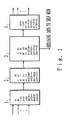
- a conventional communication system for performing a broadcast communication is shown in Figure 1.
- This system transmits data by designating the coordinate ID of the destination nodes.
- a receiving process unit 1 receives data transmitted from other nodes and a destination detection unit 2 detects the destination coordinate of the data.
- a destination judgment unit 3 judges whether the destination coordinate is the self (or local) node or other node and obtains the data when the destination coordinate designates the self node.
- a transmission process unit 4 transmits the data to the other node if the destination coordinate is for the other node.
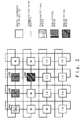
- the transmission data designates the coordinate of receiving node N67 and the data transmitted from node N61 is transferred to node N67 by being relayed via nodes N62 and N63.
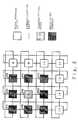
- Respective receiving nodes can only relay or receive the data. Therefore, as shown in Figure 3, the present network performs a broadcast communication from node N76 to nodes N71, N72, N73, N75, N77, N79, N710 and N711 as follows.
- the transmission source node repeats the data transmission at times corresponding to the number of the receiving node.
- a transmission is repeated so that the message is transmitted from one node to a plurality of other nodes one by one. Therefore, there is a problem that the broadcast communication cannot be performed with high speed and high efficiency.
- control of the node for relaying the data which is performed by designating the coordinates is complex.
- EP-A-0 132 926 discloses a communication control system having the features of the preamble of accompanying claim 1.
- the data being transmitted has an address specifying a unique destination node (terminal).
- a communication control system between parallel computers for performing a broadcast communication in a network between parallel nodes in which each of said nodes comprises:
- the broadcast communication is performed by worm-hole routing with high speed and high efficiency by transmitting the message divided into flits each constituting a unit of data transmission.
- a header flit selected from the flits is given the destination information specifying the scope of the broadcast transmission, thereby enabling a receiving node to refer to the scope information to preserve the message in the same node and to transmit the message to all other nodes within the scope.
- Figure 4 shows a block diagram of a principle of the present invention by explaining a structure of node 10.
- the receiving process units 11, 12 ... 1N, and 21, 22,... 2N receive the data transmitted from the other nodes in respective directions.
- a destination detecting unit 13 detects the destination information designating the scope of the destination node from the data between-node distance processing unit for obtaining a node distance between the particular computer node and the destination computer node based on the destination information.
- a destination judgment unit 15 judges whether the data should be obtained by the self node and then obtains the data. Simultaneously, the destination judgment unit 15 determines whether or not the distance is 0 based on the obtained between-node distance and then determines the direction in which the data is further transmitted. It then provides the data to the transmission processing units in respective directions. Transmission processing units 31, 32...3N, and 41, 42, 4N transmit the data provided from the destination judgment unit 15 to the destination node.
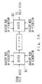
- the message is divided into transmission units of flits 51.
- Header flit 51-1 having the scope information of the broadcast communication, is provided at the head of the message and the end flit 51-2 is provided at the end of the message.
- the message is sequentially transmitted from one node 10a to the other node 10b in the network.
- the receiving node 10 refers to header flit 51-1 and when the scope information designates that the message should be transmitted to the other node 10, the scope information is updated and header flit 51-1 is transmitted to the other node 10 in the transmission direction and the following flits 51 transmitted after the header flit 51-1 are sequentially transmitted until the end flit 51-2 is transmitted.
- the scope information of the broadcast communication is provided to header flit 51-1 at the head of the flit 51 obtained by dividing the message into transmission units and then flits 51 are sequentially transmitted.
- Node 10b which receives the flit, refers to the scope information, preserves the message in the self node and transmits it to the other node 10 in the transmission direction. This operation is repeated, thereby achieving a high speed and efficient broadcast communication in the worm-hole routing.
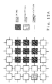
- Figure 5A shows an example of a data flow of a broadcast communication in a one dimensional network.
- 10a is a transmission node and the hatched nodes 10b designate the receiving nodes.
- the scope information of the transmission is 2 and thus the message is broadcast to the node provided two nodes ahead in both directions from transmission node 10a.
- Figure 5B shows an example of data of a broadcast communication in a two dimensional network.
- 10a designates a transmission node and the hatched nodes 10b designate the receiving nodes.
- the scope information of the transmission is 2 in the X direction and 1 in the Y direction.
- the message is broadcast to the node two nodes ahead in the +X and -X directions and is broadcast to the node provided one node ahead in the +Y and -Y directions from transmission node 10a.
- FIG. 5C shows an example of a flit.
- Flit 1 is obtained by dividing the message into transmission units (for example, units of several bytes).
- the message comprises a header flit 51-1 provided at the head of the message, flits with data and an end flit 51-2 provided at the end of the message.
- the scope information of the transmission in the broadcast communication is stored in the header flit 51-1.
- the scope information of the transmission designates the number of nodes through which the message is transmitted in a one-dimensional network and designates the number of nodes through which the message is transmitted in *X direction and *Y direction in the two-dimensional network.
- the end flit 51-2 designates EOD (end of file or the end of the flit) by making the end bit "1".
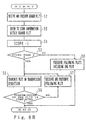
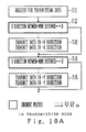
- Step S3 determines whether the content of the header flit is other than 0.
- the flits (including the header flit and the other flits) are sequentially transmitted in the transmission direction through steps S4 to S7.
- the self node is the end node of the broadcast communication and the header flit is not transmitted to the other node.
- the following flits, including the end flit, are preserved at step S8.
- step S4 1 is subtracted from the scope information of the transmission.
- the scope information of the transmission is thereby judged as being other than 0 in step S3 and transmission of the message to the other node is required.
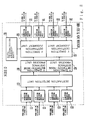
- Figure 8 shows a process block diagram of a node 10 according to the present embodiment.
- the transmission node N31 performs a broadcast communication toward respective receiving nodes in a two-dimensional lattice network as shown in Figure 9.
- step S24 then transmits data in the +Y direction.
- step S25 determines that the data should be transmitted in the Y direction, and at step S26, data is transmitted in the +Y and the -Y directions.
- the step S21 corresponds to -X direction receiving process unit 11 and destination detection unit 13 shown in Figure 4, the step S22 between-node distance process unit 14, the step S23 destination judgement unit 15, and the step S24 +X direction transmission process unit 31.
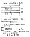
- Figure 10C and Figure 10E show respectively the process for receiving the data from a right node in the +X direction in accordance with steps S31 to S36 and the process for receiving data from an upper node in the +Y direction in accordance with steps S51 to S54.
- the scope of the broadcast communication is designated and transmitted to the data transmission request part 108, thereby forming the data designating the scope of the broadcast communication and transmitting the data to the destination judgment unit 115, in accordance with the block diagram shown in Figure 8.
Claims (6)
- Ein Kommunikationssteuersystem zwischen Parallelrechnern zum Durchführen einer Rundfunkkommunikation in einem Netzwerk zwischen parallelen Knoten (10), in welchem jeder der Knoten (10) umfaßt:Datenempfangsmittel (11, 12, .... 1N; 21, 22, ... 2N) zum Empfangen der von anderen Knoten in jeweiligen Richtungen übertragenen Daten;ein Zieldetektionsmittel (13) zum Detektieren einer Zielinformation aus den Daten;ein Verarbeitungsmittel (14) für einen Abstand zwischen Knoten zum Erhalten einer Abstandsinformation zwischen einem speziellen Rechnerknoten und dem Zielknoten, beruhend auf der Zielinformation;ein Zielentscheidungsmittel (15) zum Entscheiden, ob die Daten durch einen lokalen Knoten erhalten werden sollen, zum Entscheiden, ob die Daten weiter zu einem anderen Knoten übertragen werden sollen, und zum Bestimmen einer Richtung der Übertragung, beruhend auf der Abstandsinformation; undÜbertragungsprozeßmittel (31, 32, ... 3N; 41, 42, ... 4N) zum Übertragen der Daten, deren Ziel bezüglich einer speziellen Richtung entschieden ist; dadurch gekennzeichnet, daß:die Zielinformation einen Bereich von Zielknoten für die Daten bezeichnet, und dadurch, daß die Übertragungsprozeßmittel eingerichtet sind, um die Daten zu allen anderen Knoten innerhalb des Bereichs zu übertragen.
- Das Kommunikationssteuersystem nach Anspruch 1, worin der Bereich der Zielknoten als ein symmetrisches Gebiet mit einem Ursprungsknoten als der Mitte des symmetrischen Gebiets bestimmt ist.
- Das Kommunikationssteuersystem nach Anspruch 1, worin der Bereich der Zielknoten in einer Richtung bezüglich eines symmetrischen Bereichs der Zielknoten mit dem Ursprungsknoten als der Mitte verschoben ist.
- Das Kommunikationssteuersystem nach Anspruch 1, worin der Bereich der Zielknoten bestimmt ist, ohne einen Ursprungsknoten innerhalb des Bereichs des Zielknotens vorzusehen.
- Das Kommunikationssteuersystem nach Anspruch 1, worin die parallelen Knoten (10) Rechner umfassen, die in einer N-dimensionalen Torusverbindung oder einer N-dimensionalen Matrixverbindung verbunden sind.
- Das Kommunikationssteuersystem nach Anspruch 1, ferner umfassend Mittel zum Einteilen der Daten in eine Vielzahl von Flits, die Übertragungseinheiten der Kommunikation bilden, enthaltend:ein Kopfflit an dem Kopf der Daten, das die Zielinformation enthält, die einen Bereich von Zielknoten bezeichnet, und ein Endflit an dem Ende der Daten; und worinin jedem Knoten (10) als Antwort auf einen Empfang des Kopfflit durch die Datenempfangsmittel das Zieldetektionsmittel (13), das Verarbeitungsmittel (14) für einen Abstand zwischen Knoten, das Zielentscheidungsmittel (15) und die Übertragungsprozeßmittel den Bereich der Übertragung aktualisieren und das Kopfflit zu einem anderen Knoten übertragen, der in der Übertragungsrichtung vorgesehen ist, wenn die Bereichsinformation in dem Kopfflit angibt, daß die Nachricht zu anderen Knoten übertragen werden soll, wodurch die dem Kopfflit folgenden Flits sequentiell übertragen werden, bis das Endflit übertragen ist.
Applications Claiming Priority (4)
| Application Number | Priority Date | Filing Date | Title |
|---|---|---|---|
| JP01240186A JP3087900B2 (ja) | 1989-09-18 | 1989-09-18 | 並列計算機を構成する計算機ノード |
| JP240186/89 | 1989-09-18 | ||
| JP1279055A JPH088569B2 (ja) | 1989-10-26 | 1989-10-26 | 放送通信方式 |
| JP279055/89 | 1989-10-26 |
Publications (3)
| Publication Number | Publication Date |
|---|---|
| EP0419201A2 EP0419201A2 (de) | 1991-03-27 |
| EP0419201A3 EP0419201A3 (en) | 1992-05-13 |
| EP0419201B1 true EP0419201B1 (de) | 1996-11-27 |
Family
ID=26534616
Family Applications (1)
| Application Number | Title | Priority Date | Filing Date |
|---|---|---|---|
| EP90310181A Expired - Lifetime EP0419201B1 (de) | 1989-09-18 | 1990-09-18 | Übertragungsteuerungssystem zwischen Parallelrechnern |
Country Status (4)
| Country | Link |
|---|---|
| US (1) | US5553078A (de) |
| EP (1) | EP0419201B1 (de) |
| AU (1) | AU633352B2 (de) |
| DE (1) | DE69029239T2 (de) |
Families Citing this family (9)
| Publication number | Priority date | Publication date | Assignee | Title |
|---|---|---|---|---|
| JP3639319B2 (ja) * | 1994-01-25 | 2005-04-20 | 富士通株式会社 | 並列計算機システム,データ転送制御方法および送受信制御装置 |
| US5822605A (en) * | 1994-03-24 | 1998-10-13 | Hitachi, Ltd. | Parallel processor system with a broadcast message serializing circuit provided within a network |
| US5996020A (en) | 1995-07-21 | 1999-11-30 | National Security Agency | Multiple level minimum logic network |
| US6289021B1 (en) | 1997-01-24 | 2001-09-11 | Interactic Holdings, Llc | Scaleable low-latency switch for usage in an interconnect structure |
| JPH10254843A (ja) * | 1997-03-06 | 1998-09-25 | Hitachi Ltd | クロスバスイッチ、該クロスバスイッチを備えた並列計算機及びブロードキャスト通信方法 |
| US5881243A (en) * | 1997-05-07 | 1999-03-09 | Zaumen; William T. | System for maintaining multiple loop free paths between source node and destination node in computer network |
| US7027413B2 (en) * | 2001-09-28 | 2006-04-11 | Sun Microsystems, Inc. | Discovery of nodes in an interconnection fabric |
| US20070140244A1 (en) * | 2005-12-21 | 2007-06-21 | International Business Machines Corporation | Optimal algorithm for large message broadcast |
| US8274987B2 (en) | 2010-03-22 | 2012-09-25 | International Business Machines Corporation | Contention free pipelined broadcasting within a constant bisection bandwidth network topology |
Family Cites Families (13)
| Publication number | Priority date | Publication date | Assignee | Title |
|---|---|---|---|---|
| US4484325A (en) * | 1982-09-02 | 1984-11-20 | Burroughs Corporation | Four way selector switch for a five port module as a node asynchronous speed independent network of concurrent processors |
| US4598400A (en) * | 1983-05-31 | 1986-07-01 | Thinking Machines Corporation | Method and apparatus for routing message packets |
| JPS60181962A (ja) * | 1984-02-29 | 1985-09-17 | Fujitsu Ltd | 並列計算機における通信方式 |
| JPH0628361B2 (ja) * | 1984-11-27 | 1994-04-13 | 国際電信電話株式会社 | パケツト交換方式 |
| US4742511A (en) * | 1985-06-13 | 1988-05-03 | Texas Instruments Incorporated | Method and apparatus for routing packets in a multinode computer interconnect network |
| CA1252168A (en) * | 1985-07-24 | 1989-04-04 | Kenneth A. Bobey | Communications network |
| JP2900359B2 (ja) * | 1986-10-30 | 1999-06-02 | 株式会社日立製作所 | マルチプロセッサシステム |
| US4933933A (en) * | 1986-12-19 | 1990-06-12 | The California Institute Of Technology | Torus routing chip |
| US4984235A (en) * | 1987-04-27 | 1991-01-08 | Thinking Machines Corporation | Method and apparatus for routing message packets and recording the roofing sequence |
| EP0300350B1 (de) * | 1987-07-20 | 1996-09-25 | Matsushita Electric Industrial Co., Ltd. | Übertragungssystem |
| US5105424A (en) * | 1988-06-02 | 1992-04-14 | California Institute Of Technology | Inter-computer message routing system with each computer having separate routinng automata for each dimension of the network |
| JP3072646B2 (ja) * | 1989-03-20 | 2000-07-31 | 富士通株式会社 | 並列計算機間通信制御方式 |
| US5175733A (en) * | 1990-12-27 | 1992-12-29 | Intel Corporation | Adaptive message routing for multi-dimensional networks |
-
1990
- 1990-09-18 DE DE69029239T patent/DE69029239T2/de not_active Expired - Fee Related
- 1990-09-18 EP EP90310181A patent/EP0419201B1/de not_active Expired - Lifetime
- 1990-09-18 AU AU62640/90A patent/AU633352B2/en not_active Ceased
-
1995
- 1995-01-13 US US08/372,825 patent/US5553078A/en not_active Expired - Fee Related
Also Published As
| Publication number | Publication date |
|---|---|
| US5553078A (en) | 1996-09-03 |
| DE69029239D1 (de) | 1997-01-09 |
| EP0419201A3 (en) | 1992-05-13 |
| AU6264090A (en) | 1991-03-21 |
| DE69029239T2 (de) | 1997-03-27 |
| EP0419201A2 (de) | 1991-03-27 |
| AU633352B2 (en) | 1993-01-28 |
Similar Documents
| Publication | Publication Date | Title |
|---|---|---|
| US5175733A (en) | Adaptive message routing for multi-dimensional networks | |
| US5181017A (en) | Adaptive routing in a parallel computing system | |
| JP3679813B2 (ja) | 並列計算機 | |
| EP0197103B1 (de) | Belastungsausgleich für paketvermittlungsknoten | |
| EP0169455B1 (de) | Nicht eindeutige Namen für Rundschreibnachrichten | |
| US7889725B2 (en) | Computer cluster | |
| Su et al. | Adaptive deadlock-free routing in multicomputers using only one extra virtual channel | |
| US5546596A (en) | Method and apparatus for integrated local and express routing in a multiprocessor | |
| US6304568B1 (en) | Interconnection network extendable bandwidth and method of transferring data therein | |
| EP0419201B1 (de) | Übertragungsteuerungssystem zwischen Parallelrechnern | |
| JP2004533035A (ja) | クラス・ネットワーク経路指定 | |
| US5398317A (en) | Synchronous message routing using a retransmitted clock signal in a multiprocessor computer system | |
| US5825773A (en) | Switching system for transferring broadcast packet held in broadcast buffer received from input port to output ports according to the state of each output port | |
| JP3087900B2 (ja) | 並列計算機を構成する計算機ノード | |
| Ni et al. | A VLSI router design for hypercube multiprocessors | |
| JP3683211B2 (ja) | ノード間データ転送方法及びノード間データ転送装置 | |
| JPH1021208A (ja) | チャネルの決定方法 | |
| JPH01162452A (ja) | 自律形ルーチング方式 | |
| JP3409862B2 (ja) | 並列プロセッサシステム | |
| CN112532527B (zh) | 路由控制方法及人工智能处理器 | |
| JPH1166024A (ja) | クロスバスイッチ切換システム | |
| JPH088569B2 (ja) | 放送通信方式 | |
| JPH04287265A (ja) | 並列計算機の通信方法 | |
| Shepherd et al. | A gateway development system | |
| US20070133580A1 (en) | Communication System For Controlling Intercommunication Among A Plurality of Communication Nodes |
Legal Events
| Date | Code | Title | Description |
|---|---|---|---|
| PUAI | Public reference made under article 153(3) epc to a published international application that has entered the european phase |
Free format text: ORIGINAL CODE: 0009012 |
|
| AK | Designated contracting states |
Kind code of ref document: A2 Designated state(s): DE FR GB |
|
| PUAL | Search report despatched |
Free format text: ORIGINAL CODE: 0009013 |
|
| AK | Designated contracting states |
Kind code of ref document: A3 Designated state(s): DE FR GB |
|
| 17P | Request for examination filed |
Effective date: 19920702 |
|
| 17Q | First examination report despatched |
Effective date: 19950405 |
|
| GRAG | Despatch of communication of intention to grant |
Free format text: ORIGINAL CODE: EPIDOS AGRA |
|
| GRAH | Despatch of communication of intention to grant a patent |
Free format text: ORIGINAL CODE: EPIDOS IGRA |
|
| RBV | Designated contracting states (corrected) |
Designated state(s): DE GB |
|
| GRAH | Despatch of communication of intention to grant a patent |
Free format text: ORIGINAL CODE: EPIDOS IGRA |
|
| GRAA | (expected) grant |
Free format text: ORIGINAL CODE: 0009210 |
|
| AK | Designated contracting states |
Kind code of ref document: B1 Designated state(s): DE GB |
|
| REF | Corresponds to: |
Ref document number: 69029239 Country of ref document: DE Date of ref document: 19970109 |
|
| PLBE | No opposition filed within time limit |
Free format text: ORIGINAL CODE: 0009261 |
|
| STAA | Information on the status of an ep patent application or granted ep patent |
Free format text: STATUS: NO OPPOSITION FILED WITHIN TIME LIMIT |
|
| 26N | No opposition filed | ||
| PG25 | Lapsed in a contracting state [announced via postgrant information from national office to epo] |
Ref country code: DE Free format text: LAPSE BECAUSE OF NON-PAYMENT OF DUE FEES Effective date: 19980603 |
|
| REG | Reference to a national code |
Ref country code: GB Ref legal event code: IF02 |
|
| PGFP | Annual fee paid to national office [announced via postgrant information from national office to epo] |
Ref country code: GB Payment date: 20050914 Year of fee payment: 16 |
|
| GBPC | Gb: european patent ceased through non-payment of renewal fee |
Effective date: 20060918 |
|
| PG25 | Lapsed in a contracting state [announced via postgrant information from national office to epo] |
Ref country code: GB Free format text: LAPSE BECAUSE OF NON-PAYMENT OF DUE FEES Effective date: 20060918 |