EP0419050A2 - Tire side member raising and pressure-joining apparatus - Google Patents
Tire side member raising and pressure-joining apparatus Download PDFInfo
- Publication number
- EP0419050A2 EP0419050A2 EP90309176A EP90309176A EP0419050A2 EP 0419050 A2 EP0419050 A2 EP 0419050A2 EP 90309176 A EP90309176 A EP 90309176A EP 90309176 A EP90309176 A EP 90309176A EP 0419050 A2 EP0419050 A2 EP 0419050A2
- Authority
- EP
- European Patent Office
- Prior art keywords
- pressure
- rollers
- raising
- tire
- joining
- Prior art date
- Legal status (The legal status is an assumption and is not a legal conclusion. Google has not performed a legal analysis and makes no representation as to the accuracy of the status listed.)
- Granted
Links
- 238000005304 joining Methods 0.000 title claims abstract description 62
- 230000037303 wrinkles Effects 0.000 description 8
- 238000003825 pressing Methods 0.000 description 6
- 239000011324 bead Substances 0.000 description 5
- 238000005096 rolling process Methods 0.000 description 2
- VYZAMTAEIAYCRO-UHFFFAOYSA-N Chromium Chemical compound [Cr] VYZAMTAEIAYCRO-UHFFFAOYSA-N 0.000 description 1
- 239000004677 Nylon Substances 0.000 description 1
- 229910000831 Steel Inorganic materials 0.000 description 1
- 238000004519 manufacturing process Methods 0.000 description 1
- 239000000463 material Substances 0.000 description 1
- 238000000034 method Methods 0.000 description 1
- 229920001778 nylon Polymers 0.000 description 1
- 239000004033 plastic Substances 0.000 description 1
- 238000007747 plating Methods 0.000 description 1
- 239000011435 rock Substances 0.000 description 1
- 238000006748 scratching Methods 0.000 description 1
- 230000002393 scratching effect Effects 0.000 description 1
- 239000010959 steel Substances 0.000 description 1
Images


Classifications
-
- B—PERFORMING OPERATIONS; TRANSPORTING
- B29—WORKING OF PLASTICS; WORKING OF SUBSTANCES IN A PLASTIC STATE IN GENERAL
- B29D—PRODUCING PARTICULAR ARTICLES FROM PLASTICS OR FROM SUBSTANCES IN A PLASTIC STATE
- B29D30/00—Producing pneumatic or solid tyres or parts thereof
- B29D30/06—Pneumatic tyres or parts thereof (e.g. produced by casting, moulding, compression moulding, injection moulding, centrifugal casting)
- B29D30/08—Building tyres
- B29D30/20—Building tyres by the flat-tyre method, i.e. building on cylindrical drums
- B29D30/28—Rolling-down or pressing-down the layers in the building process
-
- B—PERFORMING OPERATIONS; TRANSPORTING
- B29—WORKING OF PLASTICS; WORKING OF SUBSTANCES IN A PLASTIC STATE IN GENERAL
- B29D—PRODUCING PARTICULAR ARTICLES FROM PLASTICS OR FROM SUBSTANCES IN A PLASTIC STATE
- B29D30/00—Producing pneumatic or solid tyres or parts thereof
- B29D30/06—Pneumatic tyres or parts thereof (e.g. produced by casting, moulding, compression moulding, injection moulding, centrifugal casting)
- B29D30/72—Side-walls
-
- B—PERFORMING OPERATIONS; TRANSPORTING
- B29—WORKING OF PLASTICS; WORKING OF SUBSTANCES IN A PLASTIC STATE IN GENERAL
- B29D—PRODUCING PARTICULAR ARTICLES FROM PLASTICS OR FROM SUBSTANCES IN A PLASTIC STATE
- B29D30/00—Producing pneumatic or solid tyres or parts thereof
- B29D30/06—Pneumatic tyres or parts thereof (e.g. produced by casting, moulding, compression moulding, injection moulding, centrifugal casting)
- B29D30/08—Building tyres
- B29D30/20—Building tyres by the flat-tyre method, i.e. building on cylindrical drums
- B29D30/32—Fitting the bead-rings or bead-cores; Folding the textile layers around the rings or cores
- B29D2030/3221—Folding over means, e.g. bladders or rigid arms
- B29D2030/3257—Folding over means, e.g. bladders or rigid arms using pressing rollers
Definitions
- This invention relates to a tire side member raising and pressure-joining apparatus for raising side members and pressure-joining the raised side members to side wall portions while a toroid-shaped semi-produced tire is being rotated.
- Tire side member raising and pressure-bonding apparatuses have been known, for example, as disclosed in Japanese Patent Application Laid-open No. 52-108,469.
- a disclosed apparatus includes a disc-shaped pressing roller 2 rotatable about its axis A perpendicular to a rotating axis of a semi-produced tire 1, a column-shaped raising roller 3 rotatable about its axis B perpendicular to the rotating axis A of the roller 2 and a non-rotatable shield 4 arranged between the rollers 2 and 3.
- a side member 5 is raised by means of the raising roller 3 and the raised side member 5 is then pressure-joined to a side wall portion 6 of the tire by means of the pressing roller 2.
- a tire side member raising and pressure-joining apparatus comprises support shafts, raising rollers ea supported by a forward end of ea of the support shafts rotatably about a center axis of the relevant support shaft as a rotating axis and being frustoconical tapered toward its free end, and pressure-joining rollers ea supported at a distal end of the forward end of ea of the support shafts rotatably about a rotating axis perpendicular to the center axis of the relevant support shaft, and parts of the pressure-joining rollers extending from free ends of the raising rollers, respectively, whereby while a toroid-shaped semi-produced tire is being rotated, side members are raised by the raising rollers and the raised side members are pressure-joined to sidewall portions of the semi-produced tire by the pressure-joining rollers.
- the pressure-joining rollers In raising and pressure-joining side members of a semi-produced tire, the pressure-joining rollers are moved to side members of the semi-produced tire rotating about its rotating axis and brought into contact with the side members. At this time, as parts of the pressure-joining rollers extend from the free ends of the raising rollers, portions of the side members radially outwardly of those of the side members in contact with the pressure-joining rollers come into contact with outer circumferences of the raising rollers. In this case, as the raising rollers are frustoconical, tapered toward their free ends, raising forces in oblique outward directions are given to the side members by the raising rollers.
- the raising rollers are rotatable about center axes of the support shafts, the outer circumferences of the raising rollers and the side members are in rolling contact with ea other, with the result that the side members are not subjected to any undue forces from the raising rollers in raising the side members.
- the side members are reliably raised by the raising rollers with high efficiency without causing any wrinkles, flaws and the like.
- the thus raised side members are then urged and pressure-joined to sidewall portions of the semi-produced tire by the rotating pressure-joining rollers.
- the side members In raising and pressure-joining the side members, if center axes of the support shafts are inclined at constant angles with respect to the rotating axis of the semi-produced tire, the side members can be raised stably all over the side members without causing any wrinkles, flaws and the like.
- an apparatus includes a frame 11 supporting a movable frame 13 reciprocatively moving by a motor 12 in radial directions of a semi-produced tire T, for example, toroidally expanded green case.
- a semi-produced tire T for example, toroidally expanded green case.
- Radially inner ends of side treads S as side members are attached under pressure on axially outer surfaces of bead portions R of the tire T.
- a guide plate 14 On a forward end of the movable frame 13 is mounted a guide plate 14 extending in parallel with a rotating axis G of the tire T for supporting a pair of blocks 15 and 16 movable along the guide plate 14.
- the movable blocks 15 and 16 are moved toward and away from ea other in opposite directions by a motor 17.
- Ea of the movable blocks 15 and 16 rockably supports a bottom end of a rocking arm 18 or 19 which is rockable in a plane including the rotating axis G of the tire T by means of a rotary actuator 20 or 21 mounted on the movable block 15 or 16.
- a support shaft 26 is fixed to the other end of ea of the rocking arms 18 and 19.
- a pair of bearings 27 and 28 are interposed between the support shaft 26 and a raising roller 29 which is light-weight and made of a plastic material (for example, MC nylon) for smooth rotation of the raising roller 29 (Fig. 3).
- a raising roller 29 which is light-weight and made of a plastic material (for example, MC nylon) for smooth rotation of the raising roller 29 (Fig. 3).
- ea of the raising rollers 29 is supported by the support shaft 26 freely rotatably about a center axis H of the support shaft 26.
- the rotation of the raising rollers 29 is very smooth, the side treads S are not subjected to undue forces and hence winkles and flaws are not caused in the side treads S when the side treads S are raised.
- Ea of the raising rollers 29 outwardly surrounds a forward end of the support shaft 26 and is frustoconical which is tapered toward a free end of the raising roller 29.
- a taper angle P of the raising roller 29 is preferably 39° to 49°. If the taper angle P is less than 39°, there is a tendency for the side treads S to cause wrinkles or flaws therein when the side treads S are raised. On the other hand, if the taper angle P is more than 49°, elongations of the side treads S in oblique outward directions become excessively large.
- intersection angles K are preferably 20° to 30°. If the intersection angles K are less than 20°, forces in oblique outward directions acting upon the side treads S by the raising rollers 29 become low tending to cause wrinkles in the side treads S. On the other hand, the intersection angles K are more than 30°, the above forces become large to give rise to large elongations in the side treads S. In this embodiment, the intersection angles K are 25°.
- a pin 35 is fixed to the free end of ea of the support shafts 26.
- a pressure-joining roller 36 in the form of a disc made of a steel is supported through a bearing (not shown) on the pin 35 rotatably about a rotating axis M perpendicular to the center axis H of the support shaft 26.
- Part (edge) of the pressure-joining roller 36 extends beyond a forward end surface 37 of the raising roller 29 by an extending distance N which is preferably 8 mm to 12 mm.
- the extending distance N is less than 8 mm, there is a risk of flaws occurring in the side treads S due to the raising rollers 29 when the side treads S are raised and pressure-joined.
- the extending distance N is more than 12 mm, wrinkles tend to occur in the side treads S.
- the outer edge of the pressure-joining roller 36 is formed to be semicircular in section in order to prevent the roller 36 from scratching the side tread S when it is being raised. A surface of the pressure-joining roller 36 may be treated by hard chrome plating, if required.
- These pressure-joining rollers 36 are pressed against the side treads S by rotating force of the rotary actuators 20 and 21 to pressure-join the side treads S to sidewall portions Q of the tire T.
- Pressing force of the pressure-joining rollers 36 against the side treads S is preferably 3.3 kgf to 6.0 kgf. If the pressing force is less than 3.3 kgf, there is a risk of air entering between the tire T and the side treads S. On the other hand, if the pressing force is more than 6.0 kgf, elongations of the side treads S become too large when they are raised and pressure-joined.
- air pressure to be supplied into the rotary actuators 20 and 21 may be kept at a relatively low constant value depending up sizes of the side treads S or high pressure may be supplied into the actuators part of the way and thereafter the pressure may be replaced with low pressure.
- the motor 12 is energized to move the movable frame 13 toward the tire T, whereas the rocking arms 18 and 19 are rocked away from ea other, with the result that the pressure-joining rollers 36 are moved from the positions c to positions d.
- the rocking arms 18 and 19 are then rocked toward ea other so that the pressure-joining rollers 36 are moved from the positions d to positions e.
- the movable frame 13 is moved away from the tire T and the movable blocks 15 and 16 are moved toward ea other so that the pressure-joining rollers 36 are moved from the positions e to positions f.
- the raising rollers 29 together with the pressure-joining rollers 36 move bypassing the side treads S onto axially outer sides of bead portions R of the tire T.
- the pressure-joining rollers 36 are moved from the positions f to positions g so as to be in contact with axially outer surfaces of the bead portions R of the tire T.
- the rocking arms 18 and 19 are rocked away from ea other against the rotating forces of the rotary actuators 20 and 21. Consequently, the pressure-joining rollers 36 are in contact with outer surfaces of the tire T with predetermined contact pressures.
- the tire T and the rims 46 of the tire building machine are rotated in unison at a low speed, while the movable frame 13 is moved away from the tire T.
- the pressure-joining rollers 36 are rotated by rotating force received from outer surfaces of the tire T and spirally moved on the outer surfaces of the tire T in radially outward directions, urging the tire T in radially inward directions thereof.
- outer surfaces of the radially inner ends of the side treads S come into contact with outer circumferences of the raising rollers 29.
- the raising rollers 29 are frustoconical which is tapered toward the free end, the raising rollers 29 provide raising forces in oblique outward directions shown by the arrow in Fig. 3 to the side treads S. Moreover, as the raising rollers 29 are rotatable about the center axes H of the support shafts 26, the outer circumferences of the raising rollers 29 and the side treads S become in rolling contact with ea other, with the result that the side treads S are not subjected to any undue forces from the raising rollers 29 in raising the side treads S.
- the side treads S are reliably raised by the raising rollers 29 with high efficiency without causing any wrinkles, flaws and the like.
- the thus raised side treads S are then urged and pressure-joined to the sidewall portions Q of the tire T by means of the pressure-joining rollers 36.
- outer surfaces of the sidewall portions Q are curved. Therefore, when the side treads S are raised and pressure-joined by the rollers 29 and 36, the movable blocks 15 and 16 are moved toward and away from ea other depending upon degrees of the curves of the sidewall portions Q to control the support shafts 26 so as to always maintain constant the intersection angles K of the center axes H of the support shafts 26 with respect to the rotating axis G of the tire T.
- the raising rollers 29 and the pressure-joining rollers 36 move radially outwardly along the outer surfaces of the tire T, while the side treads S are raised and pressure-joined by the rollers 29 and 36 in this manner.
- the pressing rollers 36 arrive at positions h shown in Fig. 2. Thereafter, the movable frame 13 is moved away from the tire T and the pressure-joining rollers 36 are moved to the positions b.
- the rocking arms 18 and 19 are then rocked away from ea other so that the pressure-joining rollers 36 are returned to the initial poising positions a.
- a belt and a tread band are then incorporated in the tire thus joined with the side treads S to form a green tire.
- the green tire is then removed from the tire building machine and transferred to a next station for a next process.
- the above is one cycle of the operation of the apparatus of the embodiment of the invention. Thereafter, such an operation is repeated for continuously producing tires.
- side members can be raised and pressure-joined with high efficiency without causing any wrinkles and flaws according to the invention.
Landscapes
- Engineering & Computer Science (AREA)
- Mechanical Engineering (AREA)
- Tyre Moulding (AREA)
- Tires In General (AREA)
- Road Paving Machines (AREA)
- Lining Or Joining Of Plastics Or The Like (AREA)
Abstract
Description
- This invention relates to a tire side member raising and pressure-joining apparatus for raising side members and pressure-joining the raised side members to side wall portions while a toroid-shaped semi-produced tire is being rotated.
- Tire side member raising and pressure-bonding apparatuses have been known, for example, as disclosed in Japanese Patent Application Laid-open No. 52-108,469. As shown in Fig. 1, such a disclosed apparatus includes a disc-shaped pressing roller 2 rotatable about its axis A perpendicular to a rotating axis of a semi-produced tire 1, a column-shaped raising
roller 3 rotatable about its axis B perpendicular to the rotating axis A of the roller 2 and anon-rotatable shield 4 arranged between therollers 2 and 3. With this apparatus, while the toroid-shaped semi-produced tire is being rotated, a side member 5 is raised by means of the raisingroller 3 and the raised side member 5 is then pressure-joined to a side wall portion 6 of the tire by means of the pressing roller 2. - However, as such a
roller 3 is rotated about the rotating axis B in parallel with the axis of the semi-produced tire 1 and is also column-shaped, it is very difficult, if not impossible, for theroller 3 to cause a force for raising the side member 5 in an oblique outward direction as shown by an arrow in Fig. 1. Therefore, it takes mu time to raise the side member 5 by theroller 3, with resulting low production efficiency. What is worse still, the side member 5 is unduly subjected to a force by theroller 3 to cause winkles or scratches or flaws in the side member 5. Such winkles are also caused by thenon-rotatable shield 4 contacting the side member 5. - It is an object of the invention to provide a tire side member raising and pressure-joining apparatus which is able to raise side members and pressure-join the raised side members to a semi-produced tire with high efficiency without causing any winkles and scratches or flaws in the side members.
- In order to accomplish the object, a tire side member raising and pressure-joining apparatus according to the invention comprises support shafts, raising rollers ea supported by a forward end of ea of the support shafts rotatably about a center axis of the relevant support shaft as a rotating axis and being frustoconical tapered toward its free end, and pressure-joining rollers ea supported at a distal end of the forward end of ea of the support shafts rotatably about a rotating axis perpendicular to the center axis of the relevant support shaft, and parts of the pressure-joining rollers extending from free ends of the raising rollers, respectively, whereby while a toroid-shaped semi-produced tire is being rotated, side members are raised by the raising rollers and the raised side members are pressure-joined to sidewall portions of the semi-produced tire by the pressure-joining rollers.
- In raising and pressure-joining side members of a semi-produced tire, the pressure-joining rollers are moved to side members of the semi-produced tire rotating about its rotating axis and brought into contact with the side members. At this time, as parts of the pressure-joining rollers extend from the free ends of the raising rollers, portions of the side members radially outwardly of those of the side members in contact with the pressure-joining rollers come into contact with outer circumferences of the raising rollers. In this case, as the raising rollers are frustoconical, tapered toward their free ends, raising forces in oblique outward directions are given to the side members by the raising rollers. Moreover, as the raising rollers are rotatable about center axes of the support shafts, the outer circumferences of the raising rollers and the side members are in rolling contact with ea other, with the result that the side members are not subjected to any undue forces from the raising rollers in raising the side members.
- Consequently, the side members are reliably raised by the raising rollers with high efficiency without causing any wrinkles, flaws and the like. The thus raised side members are then urged and pressure-joined to sidewall portions of the semi-produced tire by the rotating pressure-joining rollers.
- In raising and pressure-joining the side members, if center axes of the support shafts are inclined at constant angles with respect to the rotating axis of the semi-produced tire, the side members can be raised stably all over the side members without causing any wrinkles, flaws and the like.
- The invention will be more fully understood by referring to the following detailed specification and claims taken in connection with the appended drawings.
- Fig. 1 is a partial sectional view of a raising and pressure-joining apparatus of the prior art;
- Fig. 2 is a schematic plan view wholly illustrating one embodiment of the apparatus according to the invention; and
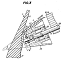
- Fig. 3 is a sectional plan view illustrating the proximity of the support shaft, raising roller and pressure-joining roller in raising and pressure-joining a side member.
- Referring to Figs. 2 and 3, an apparatus according to the invention includes a frame 11 supporting a
movable frame 13 reciprocatively moving by amotor 12 in radial directions of a semi-produced tire T, for example, toroidally expanded green case. Radially inner ends of side treads S as side members are attached under pressure on axially outer surfaces of bead portions R of the tire T. - On a forward end of the
movable frame 13 is mounted aguide plate 14 extending in parallel with a rotating axis G of the tire T for supporting a pair ofblocks guide plate 14. Themovable blocks motor 17. Ea of themovable blocks arm 18 or 19 which is rockable in a plane including the rotating axis G of the tire T by means of arotary actuator movable block - A
support shaft 26 is fixed to the other end of ea of the rockingarms 18 and 19. A pair ofbearings support shaft 26 and a raisingroller 29 which is light-weight and made of a plastic material (for example, MC nylon) for smooth rotation of the raising roller 29 (Fig. 3). As a result, ea of the raisingrollers 29 is supported by thesupport shaft 26 freely rotatably about a center axis H of thesupport shaft 26. As the rotation of the raisingrollers 29 is very smooth, the side treads S are not subjected to undue forces and hence winkles and flaws are not caused in the side treads S when the side treads S are raised. - Ea of the raising
rollers 29 outwardly surrounds a forward end of thesupport shaft 26 and is frustoconical which is tapered toward a free end of the raisingroller 29. A taper angle P of the raisingroller 29 is preferably 39° to 49°. If the taper angle P is less than 39°, there is a tendency for the side treads S to cause wrinkles or flaws therein when the side treads S are raised. On the other hand, if the taper angle P is more than 49°, elongations of the side treads S in oblique outward directions become excessively large. - When the side treads S are being raised by the raising
rollers 29, the center axes H of the support shafts 26 ( coaxial with rotating axes of the raising rollers 29) are always inclined at constant intersection angles K with respect to the rotating axis G of the tire T (a straight line J in parallel with the axis G in Fig. 3). By always keeping the intersection angles K constant in raising the side treads S in this manner, they can be stably raised over all areas without causing wrinkles, flaws and the like. - In this case, the intersection angles K are preferably 20° to 30°. If the intersection angles K are less than 20°, forces in oblique outward directions acting upon the side treads S by the raising
rollers 29 become low tending to cause wrinkles in the side treads S. On the other hand, the intersection angles K are more than 30°, the above forces become large to give rise to large elongations in the side treads S. In this embodiment, the intersection angles K are 25°. - A
pin 35 is fixed to the free end of ea of thesupport shafts 26. A pressure-joiningroller 36 in the form of a disc made of a steel is supported through a bearing (not shown) on thepin 35 rotatably about a rotating axis M perpendicular to the center axis H of thesupport shaft 26. Part (edge) of the pressure-joiningroller 36 extends beyond aforward end surface 37 of the raisingroller 29 by an extending distance N which is preferably 8 mm to 12 mm. - If the extending distance N is less than 8 mm, there is a risk of flaws occurring in the side treads S due to the raising
rollers 29 when the side treads S are raised and pressure-joined. On the other hand, if the extending distance N is more than 12 mm, wrinkles tend to occur in the side treads S. Moreover, the outer edge of the pressure-joiningroller 36 is formed to be semicircular in section in order to prevent theroller 36 from scratching the side tread S when it is being raised. A surface of the pressure-joiningroller 36 may be treated by hard chrome plating, if required. - These pressure-joining
rollers 36 are pressed against the side treads S by rotating force of therotary actuators rollers 36 against the side treads S is preferably 3.3 kgf to 6.0 kgf. If the pressing force is less than 3.3 kgf, there is a risk of air entering between the tire T and the side treads S. On the other hand, if the pressing force is more than 6.0 kgf, elongations of the side treads S become too large when they are raised and pressure-joined. In order to accomplish good pressure-joining of the side treads, moreover, air pressure to be supplied into therotary actuators - The operation of the apparatus of this embodiment will be explained hereinafter.
- It is now assumed that a semi-produced tire T mounted on
rims 46 of a tire building machine has been inflated in a toroidal shape. At this time, radially inner ends of side treads S are attached to outer side surfaces of bead portions R of the tire T, while the pressure-joiningrollers 36 are awaiting at poising positions a shown in Fig. 2. - When the
rotary actuators arms 18 and 19 toward ea other, the pressure-joiningrollers 36 are moved from the poising positions a to positions b. Themotor 17 is then energized to move themovable blocks rollers 36 are moved from the positions b to positions c. - Thereafter, the
motor 12 is energized to move themovable frame 13 toward the tire T, whereas therocking arms 18 and 19 are rocked away from ea other, with the result that the pressure-joiningrollers 36 are moved from the positions c to positions d. The rockingarms 18 and 19 are then rocked toward ea other so that the pressure-joiningrollers 36 are moved from the positions d to positions e. Thereafter, themovable frame 13 is moved away from the tire T and themovable blocks rollers 36 are moved from the positions e to positions f. During the above movements of pressure-joiningrollers 36 in the above passages, the raisingrollers 29 together with the pressure-joiningrollers 36 move bypassing the side treads S onto axially outer sides of bead portions R of the tire T. - When the
movable blocks rollers 36 are moved from the positions f to positions g so as to be in contact with axially outer surfaces of the bead portions R of the tire T. As themovable blocks rollers 36 with the bead portions R, therocking arms 18 and 19 are rocked away from ea other against the rotating forces of therotary actuators rollers 36 are in contact with outer surfaces of the tire T with predetermined contact pressures. The rocking movements of the rockingarms 18 and 19 and hence the movements of themovable blocks support shafts 26 become the above described value. - Thereafter, the tire T and the
rims 46 of the tire building machine are rotated in unison at a low speed, while themovable frame 13 is moved away from the tire T. As a result, the pressure-joiningrollers 36 are rotated by rotating force received from outer surfaces of the tire T and spirally moved on the outer surfaces of the tire T in radially outward directions, urging the tire T in radially inward directions thereof. By such movements of the pressure-joiningrollers 36, outer surfaces of the radially inner ends of the side treads S come into contact with outer circumferences of the raisingrollers 29. As the edges of the pressure-joiningrollers 36 extend beyond theforward end surfaces 37 of thearising rollers 29 as above described, parts of the side treads S radially outward of those of the side treads S in contact with thepressing rollers 36 are brought into contact with the raisingrollers 29 over wide areas of the side treads S. - In this case, as the raising
rollers 29 are frustoconical which is tapered toward the free end, the raisingrollers 29 provide raising forces in oblique outward directions shown by the arrow in Fig. 3 to the side treads S. Moreover, as the raisingrollers 29 are rotatable about the center axes H of thesupport shafts 26, the outer circumferences of the raisingrollers 29 and the side treads S become in rolling contact with ea other, with the result that the side treads S are not subjected to any undue forces from the raisingrollers 29 in raising the side treads S. - Consequently, the side treads S are reliably raised by the raising
rollers 29 with high efficiency without causing any wrinkles, flaws and the like. The thus raised side treads S are then urged and pressure-joined to the sidewall portions Q of the tire T by means of the pressure-joiningrollers 36. In this case, outer surfaces of the sidewall portions Q are curved. Therefore, when the side treads S are raised and pressure-joined by therollers movable blocks support shafts 26 so as to always maintain constant the intersection angles K of the center axes H of thesupport shafts 26 with respect to the rotating axis G of the tire T. - The raising
rollers 29 and the pressure-joiningrollers 36 move radially outwardly along the outer surfaces of the tire T, while the side treads S are raised and pressure-joined by therollers pressing rollers 36 arrive at positions h shown in Fig. 2. Thereafter, themovable frame 13 is moved away from the tire T and the pressure-joiningrollers 36 are moved to the positions b. - The rocking
arms 18 and 19 are then rocked away from ea other so that the pressure-joiningrollers 36 are returned to the initial poising positions a. A belt and a tread band are then incorporated in the tire thus joined with the side treads S to form a green tire. The green tire is then removed from the tire building machine and transferred to a next station for a next process. The above is one cycle of the operation of the apparatus of the embodiment of the invention. Thereafter, such an operation is repeated for continuously producing tires. - As can be seen from the above explanation, side members can be raised and pressure-joined with high efficiency without causing any wrinkles and flaws according to the invention.
- While the invention has been particularly shown and described with reference to preferred embodiments thereof, it will be understood by those skilled in the art that the foregoing and other changes in form and details can be made therein without departing from the spirit and scope of the invention.
Claims (8)
Applications Claiming Priority (2)
| Application Number | Priority Date | Filing Date | Title |
|---|---|---|---|
| JP1989102380U JPH0517230Y2 (en) | 1989-08-31 | 1989-08-31 | |
| JP102380/89 | 1989-08-31 |
Publications (3)
| Publication Number | Publication Date |
|---|---|
| EP0419050A2 true EP0419050A2 (en) | 1991-03-27 |
| EP0419050A3 EP0419050A3 (en) | 1992-07-01 |
| EP0419050B1 EP0419050B1 (en) | 1994-10-26 |
Family
ID=14325851
Family Applications (1)
| Application Number | Title | Priority Date | Filing Date |
|---|---|---|---|
| EP90309176A Expired - Lifetime EP0419050B1 (en) | 1989-08-31 | 1990-08-21 | Tire side member raising and pressure-joining apparatus |
Country Status (4)
| Country | Link |
|---|---|
| US (1) | US5074949A (en) |
| EP (1) | EP0419050B1 (en) |
| JP (1) | JPH0517230Y2 (en) |
| ES (1) | ES2066139T3 (en) |
Cited By (2)
| Publication number | Priority date | Publication date | Assignee | Title |
|---|---|---|---|---|
| WO2010065042A3 (en) * | 2008-12-05 | 2010-08-26 | Michelin Recherche Et Technique S.A. | Method and apparatus for forming a tire component upon an axially tapered surface |
| US8980030B2 (en) | 2008-04-23 | 2015-03-17 | Michelin Recherche Et Technique S.A. | Method and apparatus for forming a multi-layered tire component |
Families Citing this family (5)
| Publication number | Priority date | Publication date | Assignee | Title |
|---|---|---|---|---|
| JP2009028966A (en) * | 2007-07-25 | 2009-02-12 | Bridgestone Corp | Device and method for manufacturing tire |
| EP2416948B1 (en) * | 2009-04-08 | 2015-03-04 | Pirelli Tyre S.p.A. | Process for manufacturing tyres for vehicle wheels |
| US8728262B2 (en) | 2011-07-12 | 2014-05-20 | The Boeing Company | Rapid fabrication of a composite part |
| JP5936849B2 (en) * | 2011-11-24 | 2016-06-22 | 東洋ゴム工業株式会社 | Pneumatic tire manufacturing method |
| CN105873751B (en) * | 2014-03-14 | 2018-08-07 | 株式会社普利司通 | Rolling device and rolling depression method |
Citations (4)
| Publication number | Priority date | Publication date | Assignee | Title |
|---|---|---|---|---|
| US1657846A (en) * | 1917-11-14 | 1928-01-31 | Firestone Tire & Rubber Co | Tire-making machine |
| US1981828A (en) * | 1932-04-28 | 1934-11-20 | Paul A Frank | Method and apparatus for building tires |
| US2605197A (en) * | 1950-04-27 | 1952-07-29 | Firestone Tire & Rubber Co | Tire building machine |
| FR2342840A1 (en) * | 1976-03-05 | 1977-09-30 | Pirelli | METHOD AND DEVICE FOR TURNING AND ASSEMBLING THE SIDEWALKS AND OTHER HALF-PRODUCTS AGAINST A TORUS-SHAPED PNEUMATIC CASING |
Family Cites Families (3)
| Publication number | Priority date | Publication date | Assignee | Title |
|---|---|---|---|---|
| US1536377A (en) * | 1914-08-10 | 1925-05-05 | Tire-making machine | |
| US3031353A (en) * | 1958-11-28 | 1962-04-24 | Nat Rubber Machinery Co | Bead stitching device for tire building machine |
| GB1244164A (en) * | 1967-12-01 | 1971-08-25 | Dunlop Holdings Ltd | Improvements in or relating to the manufacture of pneumatic tyres |
-
1989
- 1989-08-31 JP JP1989102380U patent/JPH0517230Y2/ja not_active Expired - Lifetime
-
1990
- 1990-08-21 EP EP90309176A patent/EP0419050B1/en not_active Expired - Lifetime
- 1990-08-21 ES ES90309176T patent/ES2066139T3/en not_active Expired - Lifetime
- 1990-08-21 US US07/570,658 patent/US5074949A/en not_active Expired - Fee Related
Patent Citations (4)
| Publication number | Priority date | Publication date | Assignee | Title |
|---|---|---|---|---|
| US1657846A (en) * | 1917-11-14 | 1928-01-31 | Firestone Tire & Rubber Co | Tire-making machine |
| US1981828A (en) * | 1932-04-28 | 1934-11-20 | Paul A Frank | Method and apparatus for building tires |
| US2605197A (en) * | 1950-04-27 | 1952-07-29 | Firestone Tire & Rubber Co | Tire building machine |
| FR2342840A1 (en) * | 1976-03-05 | 1977-09-30 | Pirelli | METHOD AND DEVICE FOR TURNING AND ASSEMBLING THE SIDEWALKS AND OTHER HALF-PRODUCTS AGAINST A TORUS-SHAPED PNEUMATIC CASING |
Cited By (3)
| Publication number | Priority date | Publication date | Assignee | Title |
|---|---|---|---|---|
| US8980030B2 (en) | 2008-04-23 | 2015-03-17 | Michelin Recherche Et Technique S.A. | Method and apparatus for forming a multi-layered tire component |
| WO2010065042A3 (en) * | 2008-12-05 | 2010-08-26 | Michelin Recherche Et Technique S.A. | Method and apparatus for forming a tire component upon an axially tapered surface |
| US8691034B2 (en) | 2008-12-05 | 2014-04-08 | Michelin Recherche Et Technique S.A. | Method and apparatus for forming a tire component upon an axially tapered surface |
Also Published As
| Publication number | Publication date |
|---|---|
| EP0419050A3 (en) | 1992-07-01 |
| JPH0517230Y2 (en) | 1993-05-10 |
| US5074949A (en) | 1991-12-24 |
| JPH0342635U (en) | 1991-04-23 |
| ES2066139T3 (en) | 1995-03-01 |
| EP0419050B1 (en) | 1994-10-26 |
Similar Documents
| Publication | Publication Date | Title |
|---|---|---|
| US3380115A (en) | Universal tire press loader | |
| KR20170094494A (en) | Method and apparatus for removing flash from a tire | |
| US5169483A (en) | Tire component member attaching apparatus | |
| JPS6311140B2 (en) | ||
| EP0419050B1 (en) | Tire side member raising and pressure-joining apparatus | |
| US5464489A (en) | Method for manufacturing a green radial tire using a transfer unit that is movable during pressing | |
| JPH0681705B2 (en) | Tire manufacturing apparatus and method | |
| JPH0739064B2 (en) | Belt-shaped member transfer device and transfer method | |
| EP1509388B1 (en) | A method for pressure-bonding of a breaker-tread assembly with a carcass assembly by means of stitching in the manufacture of green tyres and device for accomplishment of such method | |
| JPS62222832A (en) | Device for feeding and sewing on belt and tread onto carcassfor pneumatic tire | |
| US4941294A (en) | Grinding machine for belt materials | |
| US6343638B1 (en) | Tire belt folding drum | |
| US3332820A (en) | Band support | |
| EP0747189B1 (en) | Tyre vulcanising mould | |
| CA2038138C (en) | Tire building apparatus and method | |
| US4036275A (en) | Tire stripping apparatus | |
| JP2000280028A (en) | Conical bending roll | |
| WO1979000706A1 (en) | Workpiece holder | |
| JPH08300509A (en) | Method and apparatus for pressure fixing of tread | |
| JPH0336026A (en) | Method for forming pneumatic tire | |
| CN113165458B (en) | Process and apparatus for visual inspection of tyres | |
| GB2327396A (en) | Tyre support | |
| JPH10156968A (en) | Manufacture of tire constituting member | |
| JPH1199455A (en) | Finishing device for welded part of wheel rim for vehicle | |
| JPH02295727A (en) | Method and apparatus for taking out finished green tire |
Legal Events
| Date | Code | Title | Description |
|---|---|---|---|
| PUAI | Public reference made under article 153(3) epc to a published international application that has entered the european phase |
Free format text: ORIGINAL CODE: 0009012 |
|
| 17P | Request for examination filed |
Effective date: 19901213 |
|
| AK | Designated contracting states |
Kind code of ref document: A2 Designated state(s): DE ES FR GB IT |
|
| PUAL | Search report despatched |
Free format text: ORIGINAL CODE: 0009013 |
|
| AK | Designated contracting states |
Kind code of ref document: A3 Designated state(s): DE ES FR GB IT |
|
| 17Q | First examination report despatched |
Effective date: 19931104 |
|
| RBV | Designated contracting states (corrected) |
Designated state(s): ES FR IT |
|
| REG | Reference to a national code |
Ref country code: DE Ref legal event code: 8566 |
|
| GRAA | (expected) grant |
Free format text: ORIGINAL CODE: 0009210 |
|
| AK | Designated contracting states |
Kind code of ref document: B1 Designated state(s): ES FR IT |
|
| ITF | It: translation for a ep patent filed | ||
| ET | Fr: translation filed | ||
| REG | Reference to a national code |
Ref country code: ES Ref legal event code: FG2A Ref document number: 2066139 Country of ref document: ES Kind code of ref document: T3 |
|
| PLBE | No opposition filed within time limit |
Free format text: ORIGINAL CODE: 0009261 |
|
| STAA | Information on the status of an ep patent application or granted ep patent |
Free format text: STATUS: NO OPPOSITION FILED WITHIN TIME LIMIT |
|
| 26N | No opposition filed | ||
| PGFP | Annual fee paid to national office [announced via postgrant information from national office to epo] |
Ref country code: ES Payment date: 19990803 Year of fee payment: 10 |
|
| PGFP | Annual fee paid to national office [announced via postgrant information from national office to epo] |
Ref country code: FR Payment date: 19990810 Year of fee payment: 10 |
|
| PG25 | Lapsed in a contracting state [announced via postgrant information from national office to epo] |
Ref country code: ES Free format text: LAPSE BECAUSE OF NON-PAYMENT OF DUE FEES Effective date: 20000822 |
|
| PG25 | Lapsed in a contracting state [announced via postgrant information from national office to epo] |
Ref country code: FR Free format text: LAPSE BECAUSE OF NON-PAYMENT OF DUE FEES Effective date: 20010430 |
|
| REG | Reference to a national code |
Ref country code: FR Ref legal event code: ST |
|
| REG | Reference to a national code |
Ref country code: ES Ref legal event code: FD2A Effective date: 20010911 |
|
| PG25 | Lapsed in a contracting state [announced via postgrant information from national office to epo] |
Ref country code: IT Free format text: LAPSE BECAUSE OF NON-PAYMENT OF DUE FEES;WARNING: LAPSES OF ITALIAN PATENTS WITH EFFECTIVE DATE BEFORE 2007 MAY HAVE OCCURRED AT ANY TIME BEFORE 2007. THE CORRECT EFFECTIVE DATE MAY BE DIFFERENT FROM THE ONE RECORDED. Effective date: 20050821 |