EP0418227B1 - Plattenwärmetauscher mit fest verbundenen platten - Google Patents
Plattenwärmetauscher mit fest verbundenen platten Download PDFInfo
- Publication number
- EP0418227B1 EP0418227B1 EP88905245A EP88905245A EP0418227B1 EP 0418227 B1 EP0418227 B1 EP 0418227B1 EP 88905245 A EP88905245 A EP 88905245A EP 88905245 A EP88905245 A EP 88905245A EP 0418227 B1 EP0418227 B1 EP 0418227B1
- Authority
- EP
- European Patent Office
- Prior art keywords
- heat exchange
- plates
- plate
- inlet
- heat exchanger
- Prior art date
- Legal status (The legal status is an assumption and is not a legal conclusion. Google has not performed a legal analysis and makes no representation as to the accuracy of the status listed.)
- Expired
Links
- 230000002093 peripheral effect Effects 0.000 claims abstract description 12
- 238000003825 pressing Methods 0.000 claims description 5
- 238000000926 separation method Methods 0.000 claims description 2
- 238000007789 sealing Methods 0.000 description 5
- 229910000679 solder Inorganic materials 0.000 description 2
- 238000004026 adhesive bonding Methods 0.000 description 1
- 238000009826 distribution Methods 0.000 description 1
- 238000005304 joining Methods 0.000 description 1
- 238000004519 manufacturing process Methods 0.000 description 1
- 238000005476 soldering Methods 0.000 description 1
- 238000003466 welding Methods 0.000 description 1
Images
Classifications
-
- F—MECHANICAL ENGINEERING; LIGHTING; HEATING; WEAPONS; BLASTING
- F28—HEAT EXCHANGE IN GENERAL
- F28D—HEAT-EXCHANGE APPARATUS, NOT PROVIDED FOR IN ANOTHER SUBCLASS, IN WHICH THE HEAT-EXCHANGE MEDIA DO NOT COME INTO DIRECT CONTACT
- F28D9/00—Heat-exchange apparatus having stationary plate-like or laminated conduit assemblies for both heat-exchange media, the media being in contact with different sides of a conduit wall
- F28D9/0031—Heat-exchange apparatus having stationary plate-like or laminated conduit assemblies for both heat-exchange media, the media being in contact with different sides of a conduit wall the conduits for one heat-exchange medium being formed by paired plates touching each other
- F28D9/0043—Heat-exchange apparatus having stationary plate-like or laminated conduit assemblies for both heat-exchange media, the media being in contact with different sides of a conduit wall the conduits for one heat-exchange medium being formed by paired plates touching each other the plates having openings therein for circulation of at least one heat-exchange medium from one conduit to another
- F28D9/005—Heat-exchange apparatus having stationary plate-like or laminated conduit assemblies for both heat-exchange media, the media being in contact with different sides of a conduit wall the conduits for one heat-exchange medium being formed by paired plates touching each other the plates having openings therein for circulation of at least one heat-exchange medium from one conduit to another the plates having openings therein for both heat-exchange media
-
- F—MECHANICAL ENGINEERING; LIGHTING; HEATING; WEAPONS; BLASTING
- F28—HEAT EXCHANGE IN GENERAL
- F28D—HEAT-EXCHANGE APPARATUS, NOT PROVIDED FOR IN ANOTHER SUBCLASS, IN WHICH THE HEAT-EXCHANGE MEDIA DO NOT COME INTO DIRECT CONTACT
- F28D9/00—Heat-exchange apparatus having stationary plate-like or laminated conduit assemblies for both heat-exchange media, the media being in contact with different sides of a conduit wall
- F28D9/0062—Heat-exchange apparatus having stationary plate-like or laminated conduit assemblies for both heat-exchange media, the media being in contact with different sides of a conduit wall the conduits for one heat-exchange medium being formed by spaced plates with inserted elements
- F28D9/0075—Heat-exchange apparatus having stationary plate-like or laminated conduit assemblies for both heat-exchange media, the media being in contact with different sides of a conduit wall the conduits for one heat-exchange medium being formed by spaced plates with inserted elements the plates having openings therein for circulation of the heat-exchange medium from one conduit to another
-
- F—MECHANICAL ENGINEERING; LIGHTING; HEATING; WEAPONS; BLASTING
- F28—HEAT EXCHANGE IN GENERAL
- F28F—DETAILS OF HEAT-EXCHANGE AND HEAT-TRANSFER APPARATUS, OF GENERAL APPLICATION
- F28F3/00—Plate-like or laminated elements; Assemblies of plate-like or laminated elements
- F28F3/02—Elements or assemblies thereof with means for increasing heat-transfer area, e.g. with fins, with recesses, with corrugations
- F28F3/04—Elements or assemblies thereof with means for increasing heat-transfer area, e.g. with fins, with recesses, with corrugations the means being integral with the element
- F28F3/042—Elements or assemblies thereof with means for increasing heat-transfer area, e.g. with fins, with recesses, with corrugations the means being integral with the element in the form of local deformations of the element
- F28F3/046—Elements or assemblies thereof with means for increasing heat-transfer area, e.g. with fins, with recesses, with corrugations the means being integral with the element in the form of local deformations of the element the deformations being linear, e.g. corrugations
-
- F—MECHANICAL ENGINEERING; LIGHTING; HEATING; WEAPONS; BLASTING
- F28—HEAT EXCHANGE IN GENERAL
- F28F—DETAILS OF HEAT-EXCHANGE AND HEAT-TRANSFER APPARATUS, OF GENERAL APPLICATION
- F28F2225/00—Reinforcing means
- F28F2225/08—Reinforcing means for header boxes
-
- Y—GENERAL TAGGING OF NEW TECHNOLOGICAL DEVELOPMENTS; GENERAL TAGGING OF CROSS-SECTIONAL TECHNOLOGIES SPANNING OVER SEVERAL SECTIONS OF THE IPC; TECHNICAL SUBJECTS COVERED BY FORMER USPC CROSS-REFERENCE ART COLLECTIONS [XRACs] AND DIGESTS
- Y10—TECHNICAL SUBJECTS COVERED BY FORMER USPC
- Y10S—TECHNICAL SUBJECTS COVERED BY FORMER USPC CROSS-REFERENCE ART COLLECTIONS [XRACs] AND DIGESTS
- Y10S165/00—Heat exchange
- Y10S165/906—Reinforcement
Definitions
- the present invention refers to a plate heat exchanger comprising a package of heat exchange plates, each having a peripheral portion surrounding a heat exchange portion and several port portions with throughflow ports, the heat exchange plates being permanently joined to adjacent heat exchange plates of the package both along their peripheral portions and at a plurality of places in their heat exchange portions in such manner that they leave flow passages between adjacent heat exchange plates, the ports of the plates being aligned and forming first inlet and outlet channels through the package for a first heat exchange medium, which communicate with every second flow passage between the heat exchange plates, and second inlet and outlet channels through the package for a second heat exchange medium, which communicate with the remaining flow passages between adjacent heat exchanger plates, and wherein the port portions of each adjacent heat exchange plates, forming a flow passage isolated from the respective channel are permanently and sealingly attached to each other over an annular area between a pair of imaginary outer and inner lines surrounding the respective channel.
- Plate heat exchangers of this kind are previously known, for example from US-A-3240268 and GB-A-2005398 and WO86/05866 since the heat exchange plates are permanently joined to each other, no separate gaskets are required between the plates and nor any outer frame to hold the plates together. Therefore, it is possible to produce plate heat exchangers of this kind relatively cheaply.
- the expression "permanently joined” refers mainly to soldering but also, for example, welding or glueing.
- the object of the present invention is to eliminate the above mentioned disadvantages of the previously known permanently joined plate heat exchangers and to provide a plate heat exchanger of the initially described kind which allows a considerably higher pressure load than previously known plate heat exchangers of this kind.
- connection means are provided in the port portions of the plates to hold adjacent plates together along the said channels within the plate interspaces communicating with the respective channels, the said connection means in each case forming a permanent connection preventing separation of adjacent plates delimiting each such interspace and being located between the said outer line and the edge of the respective port.
- the connecting means are arranged in an area round the inlet and outlet channels respectively, located between said inner line and the edges of the ports.
- each connecting means at least partly constitutes an integral part of a heat exchange plate.
- the heat exchange plates are made of a thin material pressed so as to be formed with projections on both of their sides, each connecting means comprising a projection pressed out from the port portion of a heat exchange plate.
- the port portions of two adjacent plates, which port portions surround an inlet or outlet channel, communicating with the flow passage formed by the plates, are preferably placed in the two end planes of the plates, located furthest from each other, and each of the connecting means is formed of projections from two adjacent plates, which projections are permanently joined to each other.
- the connecting means placed in the different spaces between the plates are arranged in line with each other perpendicularly to the heat exchange plates along the inlet and outlet channels, respectively.
- Each inlet and outlet channel is open at one end and closed at its other end, and an end plate placed at the said other end has a non-penetrated port portion comprising connecting means, which corresponds to said connecting means of the heat exchange plates, in areas around inlet and outlet channels, and stiffening projections pressed out inside of said connecting means.
- each heat exchange plate according to the invention with connecting means also within the above said inner line in each port portion, which means is formed by pressing together with the pressing of the remaining portions of the plate, it can be avoided that the ports of the plate become oval. In this way the above mentioned margin of the area for a sealing ring at the end plate of the heat exchanger can be utilised for the forming of the just mentioned connecting means within said inner line in each port portion.
- FIG. 1 there is shown a plate heat exchanger 1, comprising a package of heat exchange plates 2, an end plate 3 and outer cover plates 4a and 4b on the upper side and the lower side respectively of the package.
- the plate heat exchanger 1 also has a first and second inlet 5 and 6 respectively and a first and second outlet 7 and 8 respectively for two heat exchange media.
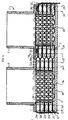
- FIG. 2 there is shown an end portion of an elongated heat exchange plate 2, provided with a pressed pattern on both of its sides, which extends between two end planes of the heat exchange plate 2.
- An obliquely projecting peripheral portion 17 extends around the periphery of the heat exchange plate, and within this there is a port portion 10a, located in one of the end planes of the plate, and a port portion 10b, located in the other end plane of the plate.
- the port portions 10a and 10b have throughflow ports 11a and 11b, respectively.
- Corresponding port portions located in said two end planes are provided at annother end portion (not shown) of the heat exchange plate 2.
- a heat exchange portion 9 located between the port portions situated at each end of the heat exchange plate 2 having a corrugation pattern consisting of ridges and valleys, extending between said two end planes.
- a corrugation pattern consisting of ridges and valleys, extending between said two end planes.
- Inside the inner line 14a there is a number of projections 15a and outside the outer line 13a there is a number of projections 16a.
- the projections 15a and 16a extend from the lower end plane to the said upper end plane.
- a connecting area 12b limited by an outer line 13b and an inner line 14b.
- there is a number of projections 15b and 16b which, however, from the upper end plane to the lower end plane.
- the heat exchange plate 2 is intended to be joined with a similar heat exchange plate which has been rotated 180° in the plane of the plate.
- a heat exchange plate located behind the heat exchange plate 2 will abut against the rear side of the connecting area 12a and against the rear side of the projections 15b and 16b, and a heat exchange plate located in front of the heat exchange plate 2 will with its rear side abut against the connecting area 12b and against the projections 15a and 16a.
- the respective heat exchange plates located on either side of the heat exchange plate 2 will abut against the respective side of the peripheral portion 17 and at a plurality of points over the respective side of the heat exchange portion 9, since the ridges and valleys of the corrugation pattern for two adjacent heat exchange plates will cross each other.
- FIG 3 there is shown an end portion of an end plate 3, comprising two non-penetrated port portions with stiffening projections 18 but which otherwise corresponds to the heat exchange plate 2 shown in Figure 2.
- the stiffening projections 18 extend from the upper end plane to the lower end plane.
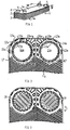
- FIG 4 there is shown a cross-section through the plate heat exchanger 1 shown in Figure 1, extending through the part of the heat exchanger comprising the second inlet pipe 6 and the first outlet pipe 7.
- This cross-section also corresponds to a corresponding cross-section through the first inlet pipe and the second outlet pipe of the heat exchanger.
- the plate heat exchanger 1 comprises eight heat exchange plates 2, of the kind shown in Figure 2, and a lower end plate 3 of the kind shown in Figure 3, which are arranged above each other between the upper, outer cover plate 4a and the lower, outer cover plate 4b.
- the ports of the heat exchange plates are aligned, so that they form an inlet channel and an outlet channel, which at the bottom are limited by the non-penetrated port portions of the end plates and which at the top communicate with the inlet pipe 6 and the outlet pipe 7, respectively.
- Two adjacent heat exchange plates 2 delimit a flow passage between the plates, in which the ridges of the corrugation pattern in the heat exchange portion of the plates cross each other.
- the connecting area 12b of one of the plates abuts against the connecting area 12a of the other plate and is permanently and sealingly attached thereto, so that each said flow passage only communicates with either the inlet channel or the outlet channel at respective end portions of the plates.
- the projections 15a and the projections 16a, respectively, of one of the plates abut against the projections 15b and the projections 16b, respectively, of the other plate.
- the projections 15a and 15b abutting each other form connecting means 19, holding together the adjacent port portions of the two heat exchange plates along the inlet and the outlet channels, respectively.
- the connecting means 19 along each of the inlet and outlet channels are located in the plate interspaces which communicate with the inlet and the outlet channel respectively in an area located between the connecting areas 12a and 12b of the plates and the channel itself. Between the connecting means 19 in respective plate interspace there are openings 22 which communicate with the flow passage between the heat exchange plates.
- the lines 13 and 14 shown in Figure 4, which delimit the connecting areas 12a and 12b of the plates, extend through the corresponding lines 13a and 13b and the lines 14a and 14b, respectively, as shown in Figure 3.
- connection means 23 along each of the inlet and outlet channels is located in the plate interspaces, which communicate with the inlet and the outlet channel, respectively, in an area which partly surrounds the inlet and the outlet channel, respectively, and which is located between the connecting areas 12a and 12b of the plates and adjacent parts of the peripheral portions 17 of the plates.
- the end plate 3 located close to the lower cover plate 4b covers the inlet and outlet channels with its non-penetrated port portions and depending on the stiffening projections 18, abutting against the cover plate 4b, and the projections which correspond to the projections 15a and 15b of the heat exchange plates, a distance ring is not required between the cover plate 4b and the end plate 3.
- the plate heat exchanger 1 comprises preferably heat exchange plates 2 with a rectangular form, but other forms could be possible, such as round heat exchange plates.
- the heat exchanger 1 is shown with one inlet channel and one outlet channel for each of the two heat exchange media, which inlet and outlet channels are located in the end portions of the heat exchange plates 2.
- a heat exchanger can of course be provided with several inlet or outlet channels. The shape of the channels and the location can be chosen freely.
- the number of heat exchange plates 2 of the heat exchanger 1 is depending on desired capacity.
- a suitable number of plates are piled on each other with solders in the shape of sheets placed between adjacent plates, whereupon the whole package is heated in an oven until said solders melt.
- the connecting means 19 can, as an alternative, be formed of separate elements arranged between and secured to the heat exchange plates, but preferably the means 19 are formed as integral parts of respective heat exchange plates.
- the means 19 are formed of the projections 15a and 15b, which are pressed out from the port portions 10a and 10b, respectively, of the heat exchange plates and which thereafter are permanently joined with corresponding projections of adjacent heat exchange plates.
- the connecting means 19 being located in the different plate interspaces, they are preferably aligned perpendicularly against the heat exchange plates 2 along respective inlet and outlet channels.
- the means 19 can be equally distributed around the inlet and outlet channels but they can also be arranged more sparsely in a direction towards the heat exchange portion 9 and more densely in remaining directions.
- the means 19 and 23 also forms a guiding for the spacing ring 20, as shown in Figure 4.
- This together with the fact that deformation of the port portions 10a and 10b can be prevented during manufacture of the heat exchange plate 2, depending on the pressing out of the projections 15a and 15b, permits the margin required for the areas 12a and 12b around the ports to be considerably reduced compared with the margin required in known heat exchangers. It is thus possible to provide the heat exchanger with connecting means 19 within the connecting areas 12a and 12b of the heat exchange plates without changing the size of the ports.
- the inlet and outlet channels are open at one end of the heat exchange package and closed at the other end of the heat exchange package. It is suitable that the end plate 3 located at said other end has a port portion without any through-port. This non-penetrated port portion is provided with the space-giving and stiffening projections 18.
Claims (8)
- Plattenwärmeaustauscher mit einem Paket aus Wärmeaustauschplatten (2) mit jeweils einem einen Wärmeaustauschbereich (9) umgebenden Umfangsbereich (17) und mehreren Durchflußöffnungen (11a, 11b) enthaltenden Öffnungsbereichen (10a, 10b), wobei die Wärmeaustauschplatten (2) permanent mit angrenzenden Wärmeaustauschplatten (2) des Pakets sowohl entlang ihrer Umfangsbereiche (17) als auch an einer Vielzahl von Orten in ihren Wärmeaustauschbereichen (9) so verbunden sind, daß Strömungskanäle zwischen nebeneinanderliegenden Wärmeaustauschplatten (2) verbleiben, wobei die Öffnungen (11a, 11b) in den Platten miteinander fluchten und durch das Paket verlaufende erste Ein- und Auslaßkanäle für ein erstes Wärmeaustauschmedium, die mit jedem zweiten Strömungskanal zwischen den Wärmeaustauschplatten (2) in Strömungsverbindung stehen, sowie durch das Paket verlaufende zweite Ein- und Auslaßkanäle für ein zweites Wärmeaustauschmedium bilden, die mit den übrigen Strömungskanälen zwischen nebeneinanderliegenden Wärmeaustauschplatten (2) in Strömungsverbindung stehen, und wobei die Öffnungsbereiche (10a, 10b) eines jeden nebeneinanderliegenden Paares von Wärmeaustauschplatten (2), die einen gegen die anderen Kanäle abgeschlossenen Strömungskanal bilden, über einen ringförmigen Bereich zwischen Paaren gedachter äußerer und innerer Linien (13a, 13b und 14a, 14b) um die jeweiligen Kanäle herum permanent und dicht abschließend miteinander verbunden sind, dadurch gekennzeichnet, daß in den Öffnungsbereichen (11a, 11b) der Platten (2) Verbindungseinrichtungen (19) vorgesehen sind, um nebeneinanderliegende Platten entlang der Kanäle innerhalb der mit den jeweiligen Kanälen in Strömungsverbindung stehenden Plattenzwischenräume zusammenzuhalten, und daß die Verbindungeinrichtungen in jedem Fall eine permanente Verbindung bilden, die eine Trennung der jeden dieser Zwischenräume bildenden nebeneinanderliegenden Platten verhindert und zwischen der äußeren Linie (13a, 13b) und der Kante der jeweiligen Öffnung (11a, 11b) liegt.
- Plattenwärmeaustauscher nach Anspruch 1, dadurch gekennzeichnet, daß die Verbindungseinrichtungen (19) in einem Bereich um den Ein- bzw. den Auslaßkanal herum zwischen der inneren linie (14a, 14b) und der Kante der jeweiligen Öffnung angeordnet sind.
- Plattenwärmeaustauscher nach Anspruch 2 oder 3, dadurch gekennzeichnet, daß jede Verbindungseinrichtung (19) mindestens teilweise einen integralen Teil einer Wärmeaustauschplatte (2) ausbildet.
- Plattenwärmeaustauscher nach Anspruch 3, dadurch gekennzeichnet, daß die Wärmeaustauschplatten (2) aus dünnem Werkstoff hergestellt und durch Pressen beidseitig mit Vorsprüngen versehen sind und daß jede Verbindungseinrichtung (19) einen aus dem Öffnungsbereich (10a, 10b) einer Wärmeaustauschplatte herausgepreßen Vorsprung (15a, 15b) aufweist.
- Plattenwärmeaustauscher nach Anspruch 4, dadurch gekennzeichnet, daß die Öffnungsbereiche (10a, 10b) zweier nebeneienanderliegender Platten (2), die einen mit dem von diesen Platten gebildeten Strömungskanal in Verbindung stehenden Ein- oder Auslaßkanal umgeben, in den Endbereichen der Platten (2) in größtmöglicher gegenseitiger Entfernung angeordnet sind und daß jede Verbindungseinrichtung (19) aus permanent miteinander verbundenen Vorsprüngen (15a, 15b) zweier nebeneinanderliegender Platten (2) gebildet ist.
- Plattenwärmeaustauscher nach Anspruch 5, dadurch gekennzeichnet, daß die in den verschiedenen Räumen zwischen den Platten befindlichen Verbindungseinrichtungen (19) in einer Linie rechtwinklig zu den Wärmeaustauschplatten (2) entlang den jeweiligen Ein- und Auslaßkanälen angeordnet sind.
- Plattenwärmeaustauscher nach Anspruch 1 oder 2, dadurch gekennzeichnet, daß die Ein- und Auslaßkanäle jeweils an einem Ende offen und am anderen Ende geschlossen sind und daß eine am anderen Ende angeordnete Abschlußplatte (3) geschlossene Öffnungsbereiche mit um die Ein- und Auslaßkanäle herum angeordneten Verbindungseinrichtungen entsprechend denen der Verbindungseinrichtungen (19) der Wärmeaustauschplatten sowie innerhalb der Verbindungseinrichtungen ausgepreßte Versteifungsbereiche (18) aufweist.
- Plattenwärmeaustauscher nach Anspruch 7 mit einer dicht auf die Abschlußplatte (3) aufgesetzten äußeren Abdeckplatte (4b), dadurch gekennzeichnet net, daß die versteifenden Vorsprünge (18) an der äußeren Abdeckplatte (4b) anliegen.
Priority Applications (1)
| Application Number | Priority Date | Filing Date | Title |
|---|---|---|---|
| AT88905245T ATE84140T1 (de) | 1987-05-29 | 1988-05-25 | Plattenwaermetauscher mit fest verbundenen platten. |
Applications Claiming Priority (2)
| Application Number | Priority Date | Filing Date | Title |
|---|---|---|---|
| SE8702258 | 1987-05-29 | ||
| SE8702258A SE458884B (sv) | 1987-05-29 | 1987-05-29 | Permanent sammanfogad plattvaermevaexlare med sammanhaallande organ vid portarna |
Publications (2)
| Publication Number | Publication Date |
|---|---|
| EP0418227A1 EP0418227A1 (de) | 1991-03-27 |
| EP0418227B1 true EP0418227B1 (de) | 1992-12-30 |
Family
ID=20368703
Family Applications (1)
| Application Number | Title | Priority Date | Filing Date |
|---|---|---|---|
| EP88905245A Expired EP0418227B1 (de) | 1987-05-29 | 1988-05-25 | Plattenwärmetauscher mit fest verbundenen platten |
Country Status (8)
| Country | Link |
|---|---|
| US (1) | US4987955A (de) |
| EP (1) | EP0418227B1 (de) |
| JP (1) | JP2719380B2 (de) |
| AT (1) | ATE84140T1 (de) |
| DE (1) | DE3877215T2 (de) |
| DK (1) | DK163897C (de) |
| SE (1) | SE458884B (de) |
| WO (1) | WO1988009473A1 (de) |
Cited By (2)
| Publication number | Priority date | Publication date | Assignee | Title |
|---|---|---|---|---|
| EP1500895A2 (de) | 2003-07-22 | 2005-01-26 | Modine Manufacturing Company | Strömungskanal für einen Wärmeaustauscher |
| EP1526350A2 (de) | 2003-10-21 | 2005-04-27 | Modine Manufacturing Company | Plattenwärmetauscher |
Families Citing this family (67)
| Publication number | Priority date | Publication date | Assignee | Title |
|---|---|---|---|---|
| SE9000712L (sv) * | 1990-02-28 | 1991-08-29 | Alfa Laval Thermal | Permanent sammanfogad plattvaermevaexlare |
| SE467275B (sv) * | 1990-05-02 | 1992-06-22 | Alfa Laval Thermal Ab | Loedd dubbelvaeggig plattvaermevaexlare med bockade kanter |
| SE502254C2 (sv) * | 1990-12-17 | 1995-09-25 | Alfa Laval Thermal Ab | Plattvärmeväxlare och förfarande för framställning av en plattvärmeväxlare |
| SE468159B (sv) * | 1991-03-25 | 1992-11-16 | Alfa Laval Thermal Ab | Foerfarande foer att belaegga vaermeoeverfoeringsplattor i en plattvaermevaexlare med ett skikt av ytskyddande material |
| US5472738A (en) * | 1991-03-25 | 1995-12-05 | Alfa Laval Thermal Ab | Method of providing heat transfer plates with a layer of a surface protecting material |
| DE4314808C2 (de) † | 1993-05-05 | 2003-10-30 | Behr Gmbh & Co | Plattenwärmetauscher, insbesondere Öl/Kühlmittel-Kühler |
| DE9309741U1 (de) * | 1993-06-30 | 1993-08-26 | Mann & Hummel Filter | Wärmetauscher |
| US5462113A (en) * | 1994-06-20 | 1995-10-31 | Flatplate, Inc. | Three-circuit stacked plate heat exchanger |
| CA2140232C (en) * | 1995-01-13 | 2004-04-13 | Peter Karl Grinbergs | Heat recovery ventilator |
| DE19549801B4 (de) * | 1995-03-31 | 2008-01-17 | Behr Gmbh & Co. Kg | Plattenwärmetauscher |
| CA2153528C (en) * | 1995-07-10 | 2006-12-05 | Bruce Laurance Evans | Plate heat exchanger with reinforced input/output manifolds |
| US5658537A (en) * | 1995-07-18 | 1997-08-19 | Basf Corporation | Plate-type chemical reactor |
| SE504868C2 (sv) * | 1995-10-23 | 1997-05-20 | Swep International Ab | Plattvärmeväxlare med ändplatta med pressat mönster |
| IT1276990B1 (it) * | 1995-10-24 | 1997-11-03 | Tetra Laval Holdings & Finance | Scambiatore di calore a piastre |
| US5964280A (en) * | 1996-07-16 | 1999-10-12 | Modine Manufacturing Company | Multiple fluid path plate heat exchanger |
| DE19711258C2 (de) * | 1997-03-18 | 1999-09-02 | Behr Gmbh & Co | Stapelscheiben-Ölkühler |
| US6179051B1 (en) | 1997-12-24 | 2001-01-30 | Delaware Capital Formation, Inc. | Distributor for plate heat exchangers |
| DK174409B1 (da) * | 1998-01-12 | 2003-02-17 | Apv Heat Exchanger As | Varmevekslerplade med forstærket kantudformning |
| SE511270C2 (sv) * | 1998-01-15 | 1999-09-06 | Alfa Laval Ab | Plattvärmeväxlare då portpartiets plan i en yttre värmeväxlingsplatta möjliggör anliggning med ändplattan |
| FI107353B (fi) * | 1998-03-04 | 2001-07-13 | Vahterus Oy | Levylämmönvaihtimen levy sekä levylämmönvaihdin |
| US6244333B1 (en) | 1998-08-27 | 2001-06-12 | Zeks Air Drier Corporation | Corrugated folded plate heat exchanger |
| US6186223B1 (en) | 1998-08-27 | 2001-02-13 | Zeks Air Drier Corporation | Corrugated folded plate heat exchanger |
| US6131648A (en) * | 1998-11-09 | 2000-10-17 | Electric Boat Corporation | High pressure corrugated plate-type heat exchanger |
| US6267176B1 (en) | 2000-02-11 | 2001-07-31 | Honeywell International Inc. | Weld-free heat exchanger assembly |
| DE10035939A1 (de) | 2000-07-21 | 2002-02-07 | Bosch Gmbh Robert | Vorrichtung zur Wärmeübertragung |
| US6878477B2 (en) * | 2001-05-15 | 2005-04-12 | Hydrogenics Corporation | Fuel cell flow field plate |
| SE519570C2 (sv) * | 2001-07-09 | 2003-03-11 | Alfa Laval Corp Ab | Värmeöverföringsplatta med flödesavgränsare; plattpaket och plattvärmeväxlare |
| DE10152363A1 (de) * | 2001-10-24 | 2003-05-08 | Modine Mfg Co | Gehäuseloser Plattenwärmetauscher |
| SE524783C2 (sv) * | 2003-02-11 | 2004-10-05 | Alfa Laval Corp Ab | Plattpaket, plattvärmeväxlare och plattmodul |
| US6976531B2 (en) * | 2003-10-22 | 2005-12-20 | Dana Canada Corporation | Heat exchanger, method of forming a sleeve which may be used in the heat exchanger, and a sleeve formed by the method |
| DE102004010640A1 (de) * | 2004-03-05 | 2005-09-22 | Modine Manufacturing Co., Racine | Plattenwärmeübertrager |
| SE526831C2 (sv) * | 2004-03-12 | 2005-11-08 | Alfa Laval Corp Ab | Värmeväxlarplatta och plattpaket |
| SE527716C2 (sv) * | 2004-04-08 | 2006-05-23 | Swep Int Ab | Plattvärmeväxlare |
| DK1630510T3 (da) * | 2004-08-28 | 2007-04-23 | Swep Int Ab | Pladevarmeveksler |
| DE102005034305A1 (de) † | 2005-07-22 | 2007-01-25 | Behr Gmbh & Co. Kg | Plattenelement für einen Plattenkühler |
| SE528886C2 (sv) * | 2005-08-26 | 2007-03-06 | Swep Int Ab | Ändplatta |
| EP1931932B1 (de) * | 2005-10-05 | 2017-09-27 | Dana Canada Corporation | Verstärkung für tellerplattenwärmetauscher |
| US20070089872A1 (en) * | 2005-10-25 | 2007-04-26 | Kaori Heat Treatment Co., Ltd. | Heat exchanger having flow control device |
| CN1837718A (zh) * | 2006-03-09 | 2006-09-27 | 缪志先 | 肋板式换热器 |
| SE529769E (sv) | 2006-04-04 | 2013-12-19 | Alfa Laval Corp Ab | Plattvärmeväxlare vilken innefattar åtminstone en förstärkningsplatta vilken är anordnad utanför en av de yttre värmeväxlarplattorna |
| DE102006048305B4 (de) * | 2006-10-12 | 2011-06-16 | Modine Manufacturing Co., Racine | Plattenwärmetauscher |
| SE532489C2 (sv) * | 2007-02-26 | 2010-02-02 | Alfa Laval Corp Ab | Plattvärmeväxlare |
| US8678076B2 (en) | 2007-11-16 | 2014-03-25 | Christopher R. Shore | Heat exchanger with manifold strengthening protrusion |
| WO2009123517A1 (en) * | 2008-04-04 | 2009-10-08 | Alfa Laval Corporate Ab | A plate heat exchanger |
| CN101983310B (zh) * | 2008-04-04 | 2012-08-22 | 阿尔法拉瓦尔股份有限公司 | 板式换热器 |
| KR101225357B1 (ko) * | 2008-04-04 | 2013-01-22 | 알파 라발 코포레이트 에이비 | 플레이트형 열교환기 |
| AU2008354068B2 (en) * | 2008-04-04 | 2013-04-04 | Alfa Laval Corporate Ab | A plate heat exchanger |
| US8596339B2 (en) * | 2008-04-17 | 2013-12-03 | Dana Canada Corporation | U-flow stacked plate heat exchanger |
| SE533067C2 (sv) * | 2008-10-03 | 2010-06-22 | Alfa Laval Corp Ab | Plattvärmeväxlare |
| US8028410B2 (en) * | 2008-12-08 | 2011-10-04 | Randy Thompson | Gas turbine regenerator apparatus and method of manufacture |
| US9004153B2 (en) | 2008-12-17 | 2015-04-14 | Swep International Ab | Port opening of brazed heat exchanger |
| DE102009041524A1 (de) * | 2009-09-15 | 2011-03-24 | Mahle International Gmbh | Plattenwärmetauscher |
| JP2011106764A (ja) * | 2009-11-19 | 2011-06-02 | Mitsubishi Electric Corp | プレート式熱交換器及びヒートポンプ装置 |
| US9163882B2 (en) | 2011-04-25 | 2015-10-20 | Itt Manufacturing Enterprises, Inc. | Plate heat exchanger with channels for ‘leaking fluid’ |
| SE537142C2 (sv) | 2012-02-14 | 2015-02-17 | Alfa Laval Corp Ab | Plattvärmeväxlare med förbättrad hållfasthet i portområdet |
| ES2706986T3 (es) * | 2012-03-28 | 2019-04-02 | Alfa Laval Corp Ab | Nuevo concepto de soldadura fuerte |
| JP6333973B2 (ja) * | 2013-10-14 | 2018-05-30 | アイレック アーベー | 熱交換器用プレートおよび熱交換器 |
| WO2015086343A1 (en) * | 2013-12-10 | 2015-06-18 | Swep International Ab | Heat exchanger with improved flow |
| CN103791759B (zh) * | 2014-03-07 | 2016-03-30 | 丹佛斯微通道换热器(嘉兴)有限公司 | 用于板式换热器的热交换板以及具有该热交换板的板式换热器 |
| DE102014217312A1 (de) * | 2014-08-29 | 2016-03-03 | Volkswagen Aktiengesellschaft | Ladeluftkühler mit verstärkter Bodenplatte und/oder Deckplatte |
| SI3093602T1 (sl) | 2015-05-11 | 2020-08-31 | Alfa Laval Corporate Ab | Plošča toplotnega izmenjevalnika in ploščni toplotni izmenjevalnik |
| KR101897514B1 (ko) * | 2016-04-11 | 2018-09-12 | 주식회사 엘에치이 | 판형 열교환기용 전열판 |
| CZ308022B6 (cs) * | 2017-12-28 | 2019-10-30 | Gascontrol, Spol. S R.O. | Velkokapacitní geotermální výměník |
| CN109668469A (zh) * | 2018-12-25 | 2019-04-23 | 天津三电汽车空调有限公司 | 一种用于汽车板式换热器上的散热板片孔口支撑结构 |
| SE544093C2 (en) * | 2019-05-21 | 2021-12-21 | Alfa Laval Corp Ab | Plate heat exchanger, and a method of manufacturing a plate heat exchanger |
| DK180387B1 (en) * | 2019-10-24 | 2021-02-26 | Danfoss As Intellectual Property | Plate kind heat exchanger with end plates |
| EP4343252A1 (de) | 2022-09-20 | 2024-03-27 | Alfa Laval Corporate AB | Plattenwärmetauscher |
Family Cites Families (14)
| Publication number | Priority date | Publication date | Assignee | Title |
|---|---|---|---|---|
| GB580368A (en) * | 1944-01-01 | 1946-09-05 | Separator Ab | Improvements in or relating to plate heat exchangers |
| DE1282037B (de) * | 1959-05-21 | 1968-11-07 | Julius & August Erbsloeh Komma | Blaehkanal-Waermetauscher |
| US3240268A (en) * | 1962-01-02 | 1966-03-15 | Gen Motors Corp | Stacked caseless heat exchangers |
| NO115396L (de) * | 1963-10-08 | 1900-01-01 | ||
| FR2280871A1 (fr) * | 1974-08-01 | 1976-02-27 | Chausson Usines Sa | Echangeur de chaleur a sous-ensembles empiles |
| DE2601231A1 (de) * | 1975-01-21 | 1976-07-22 | Apv Co Ltd | Plattenwaermetauscher |
| DE2552335A1 (de) * | 1975-11-21 | 1977-06-08 | Impulsa Veb K | Waermeuebertragungsplatten |
| DE2840522A1 (de) * | 1977-10-05 | 1979-04-19 | Alfa Laval Ab | Plattenwaermetauscher |
| US4470455A (en) * | 1978-06-19 | 1984-09-11 | General Motors Corporation | Plate type heat exchanger tube pass |
| US4229868A (en) * | 1978-10-26 | 1980-10-28 | The Garrett Corporation | Apparatus for reinforcement of thin plate, high pressure fluid heat exchangers |
| DE3141161C2 (de) * | 1981-10-16 | 1984-04-26 | W. Schmidt GmbH & Co KG, 7518 Bretten | Plattenwärmeaustauscher |
| GB2128726B (en) * | 1982-10-21 | 1986-01-08 | Apv Co Ltd | Heat exchanger plate |
| SE8501599D0 (sv) * | 1985-04-01 | 1985-04-01 | Torell Ab | Anordning vid en plattvermevexlare |
| DE3622316C1 (de) * | 1986-07-03 | 1988-01-28 | Schmidt W Gmbh Co Kg | Plattenwaermeaustauscher |
-
1987
- 1987-05-29 SE SE8702258A patent/SE458884B/sv not_active IP Right Cessation
-
1988
- 1988-05-25 JP JP63504890A patent/JP2719380B2/ja not_active Expired - Lifetime
- 1988-05-25 WO PCT/SE1988/000276 patent/WO1988009473A1/en active IP Right Grant
- 1988-05-25 AT AT88905245T patent/ATE84140T1/de not_active IP Right Cessation
- 1988-05-25 EP EP88905245A patent/EP0418227B1/de not_active Expired
- 1988-05-25 DE DE8888905245T patent/DE3877215T2/de not_active Expired - Lifetime
- 1988-05-25 US US07/295,216 patent/US4987955A/en not_active Expired - Lifetime
-
1989
- 1989-01-10 DK DK009189A patent/DK163897C/da not_active IP Right Cessation
Cited By (3)
| Publication number | Priority date | Publication date | Assignee | Title |
|---|---|---|---|---|
| EP1500895A2 (de) | 2003-07-22 | 2005-01-26 | Modine Manufacturing Company | Strömungskanal für einen Wärmeaustauscher |
| EP1526350A2 (de) | 2003-10-21 | 2005-04-27 | Modine Manufacturing Company | Plattenwärmetauscher |
| DE10348803B4 (de) | 2003-10-21 | 2024-03-14 | Modine Manufacturing Co. | Gehäuseloser Plattenwärmetauscher |
Also Published As
| Publication number | Publication date |
|---|---|
| JP2719380B2 (ja) | 1998-02-25 |
| DK9189D0 (da) | 1989-01-10 |
| DE3877215D1 (de) | 1993-02-11 |
| DK163897B (da) | 1992-04-13 |
| WO1988009473A1 (en) | 1988-12-01 |
| DK9189A (da) | 1989-01-10 |
| SE8702258L (sv) | 1988-11-30 |
| US4987955A (en) | 1991-01-29 |
| DE3877215T2 (de) | 1993-04-29 |
| SE458884B (sv) | 1989-05-16 |
| EP0418227A1 (de) | 1991-03-27 |
| SE8702258D0 (sv) | 1987-05-29 |
| JPH01503558A (ja) | 1989-11-30 |
| ATE84140T1 (de) | 1993-01-15 |
| DK163897C (da) | 1992-09-14 |
Similar Documents
| Publication | Publication Date | Title |
|---|---|---|
| EP0418227B1 (de) | Plattenwärmetauscher mit fest verbundenen platten | |
| US5924484A (en) | Plate heat exchanger | |
| AU739681B2 (en) | Three circuit plate heat exchanger | |
| US5307869A (en) | Permanently joined plate heat exchanger | |
| EP2084481B1 (de) | Plattenwärmetauscher | |
| EP1497603B1 (de) | Umgekehrte endplatte für wärmetauscher | |
| US6142221A (en) | Three-circuit plate heat exchanger | |
| CA2153528C (en) | Plate heat exchanger with reinforced input/output manifolds | |
| US20040168793A1 (en) | Plate heat exchanger | |
| CA2104905A1 (en) | All-Welded Plate Heat Exchanger | |
| CA2260890A1 (en) | Self-enclosing heat exchangers | |
| US5492171A (en) | Plate heat exchanger, a method of producing a plate heat exchanger and means for performing the method | |
| US7870671B2 (en) | Method of manufacturing a plate heat exchanger | |
| WO1988009474A1 (en) | Plate heat exchanger having permanently joined plates | |
| EP0782688B1 (de) | Plattenwärmetauscher | |
| EP4001822A1 (de) | Platten-kapsel-wärmetauscher und wärmeübertragungsplatte für platten-kapsel-wärmetauscher | |
| EP4001818A1 (de) | Platten-kapsel-wärmetauscher und wärmeübertragungsplatte für platten-kapsel-wärmetauscher | |
| CA2298116A1 (en) | Self-enclosing heat exchanger with crimped turbulizer |
Legal Events
| Date | Code | Title | Description |
|---|---|---|---|
| PUAI | Public reference made under article 153(3) epc to a published international application that has entered the european phase |
Free format text: ORIGINAL CODE: 0009012 |
|
| 17P | Request for examination filed |
Effective date: 19890214 |
|
| AK | Designated contracting states |
Kind code of ref document: A1 Designated state(s): AT BE CH DE FR GB IT LI NL SE |
|
| 17Q | First examination report despatched |
Effective date: 19910612 |
|
| GRAA | (expected) grant |
Free format text: ORIGINAL CODE: 0009210 |
|
| ITF | It: translation for a ep patent filed |
Owner name: BARZANO' E ZANARDO MILA |
|
| AK | Designated contracting states |
Kind code of ref document: B1 Designated state(s): AT BE CH DE FR GB IT LI NL SE |
|
| PG25 | Lapsed in a contracting state [announced via postgrant information from national office to epo] |
Ref country code: NL Effective date: 19921230 Ref country code: BE Effective date: 19921230 Ref country code: AT Effective date: 19921230 |
|
| REF | Corresponds to: |
Ref document number: 84140 Country of ref document: AT Date of ref document: 19930115 Kind code of ref document: T |
|
| REF | Corresponds to: |
Ref document number: 3877215 Country of ref document: DE Date of ref document: 19930211 |
|
| ET | Fr: translation filed | ||
| NLV1 | Nl: lapsed or annulled due to failure to fulfill the requirements of art. 29p and 29m of the patents act | ||
| PLBE | No opposition filed within time limit |
Free format text: ORIGINAL CODE: 0009261 |
|
| STAA | Information on the status of an ep patent application or granted ep patent |
Free format text: STATUS: NO OPPOSITION FILED WITHIN TIME LIMIT |
|
| 26N | No opposition filed | ||
| EAL | Se: european patent in force in sweden |
Ref document number: 88905245.2 |
|
| REG | Reference to a national code |
Ref country code: FR Ref legal event code: TP |
|
| REG | Reference to a national code |
Ref country code: FR Ref legal event code: GC |
|
| REG | Reference to a national code |
Ref country code: GB Ref legal event code: IF02 |
|
| REG | Reference to a national code |
Ref country code: GB Ref legal event code: 732E |
|
| REG | Reference to a national code |
Ref country code: FR Ref legal event code: RG |
|
| PG25 | Lapsed in a contracting state [announced via postgrant information from national office to epo] |
Ref country code: IT Free format text: LAPSE BECAUSE OF NON-PAYMENT OF DUE FEES Effective date: 20050525 |
|
| PGFP | Annual fee paid to national office [announced via postgrant information from national office to epo] |
Ref country code: SE Payment date: 20070508 Year of fee payment: 20 |
|
| PGFP | Annual fee paid to national office [announced via postgrant information from national office to epo] |
Ref country code: DE Payment date: 20070517 Year of fee payment: 20 |
|
| PGFP | Annual fee paid to national office [announced via postgrant information from national office to epo] |
Ref country code: CH Payment date: 20070530 Year of fee payment: 20 |
|
| PGFP | Annual fee paid to national office [announced via postgrant information from national office to epo] |
Ref country code: GB Payment date: 20070523 Year of fee payment: 20 |
|
| PGFP | Annual fee paid to national office [announced via postgrant information from national office to epo] |
Ref country code: FR Payment date: 20070510 Year of fee payment: 20 Ref country code: IT Payment date: 20070525 Year of fee payment: 20 |
|
| PGRI | Patent reinstated in contracting state [announced from national office to epo] |
Ref country code: IT Effective date: 20080301 |
|
| REG | Reference to a national code |
Ref country code: GB Ref legal event code: PE20 Expiry date: 20080524 |
|
| REG | Reference to a national code |
Ref country code: CH Ref legal event code: PL |
|
| EUG | Se: european patent has lapsed | ||
| PG25 | Lapsed in a contracting state [announced via postgrant information from national office to epo] |
Ref country code: GB Free format text: LAPSE BECAUSE OF EXPIRATION OF PROTECTION Effective date: 20080524 |