EP0417800B1 - Circuit électronique de sûreté pour un appareil électroménager commandé par un moteur électrique - Google Patents
Circuit électronique de sûreté pour un appareil électroménager commandé par un moteur électrique Download PDFInfo
- Publication number
- EP0417800B1 EP0417800B1 EP90117686A EP90117686A EP0417800B1 EP 0417800 B1 EP0417800 B1 EP 0417800B1 EP 90117686 A EP90117686 A EP 90117686A EP 90117686 A EP90117686 A EP 90117686A EP 0417800 B1 EP0417800 B1 EP 0417800B1
- Authority
- EP
- European Patent Office
- Prior art keywords
- electric motor
- safety circuit
- switch
- main switch
- electronic safety
- Prior art date
- Legal status (The legal status is an assumption and is not a legal conclusion. Google has not performed a legal analysis and makes no representation as to the accuracy of the status listed.)
- Expired - Lifetime
Links
Images

Classifications
-
- A—HUMAN NECESSITIES
- A47—FURNITURE; DOMESTIC ARTICLES OR APPLIANCES; COFFEE MILLS; SPICE MILLS; SUCTION CLEANERS IN GENERAL
- A47J—KITCHEN EQUIPMENT; COFFEE MILLS; SPICE MILLS; APPARATUS FOR MAKING BEVERAGES
- A47J42/00—Coffee mills; Spice mills
- A47J42/38—Parts or details
- A47J42/56—Safety devices
-
- A—HUMAN NECESSITIES
- A47—FURNITURE; DOMESTIC ARTICLES OR APPLIANCES; COFFEE MILLS; SPICE MILLS; SUCTION CLEANERS IN GENERAL
- A47J—KITCHEN EQUIPMENT; COFFEE MILLS; SPICE MILLS; APPARATUS FOR MAKING BEVERAGES
- A47J43/00—Implements for preparing or holding food, not provided for in other groups of this subclass
- A47J43/04—Machines for domestic use not covered elsewhere, e.g. for grinding, mixing, stirring, kneading, emulsifying, whipping or beating foodstuffs, e.g. power-driven
- A47J43/07—Parts or details, e.g. mixing tools, whipping tools
- A47J43/075—Safety devices
-
- F—MECHANICAL ENGINEERING; LIGHTING; HEATING; WEAPONS; BLASTING
- F16—ENGINEERING ELEMENTS AND UNITS; GENERAL MEASURES FOR PRODUCING AND MAINTAINING EFFECTIVE FUNCTIONING OF MACHINES OR INSTALLATIONS; THERMAL INSULATION IN GENERAL
- F16P—SAFETY DEVICES IN GENERAL; SAFETY DEVICES FOR PRESSES
- F16P3/00—Safety devices acting in conjunction with the control or operation of a machine; Control arrangements requiring the simultaneous use of two or more parts of the body
- F16P3/08—Safety devices acting in conjunction with the control or operation of a machine; Control arrangements requiring the simultaneous use of two or more parts of the body in connection with the locking of doors, covers, guards, or like members giving access to moving machine parts
- F16P3/10—Safety devices acting in conjunction with the control or operation of a machine; Control arrangements requiring the simultaneous use of two or more parts of the body in connection with the locking of doors, covers, guards, or like members giving access to moving machine parts in which the operation of locking the door or other member causes the machine to start
-
- H—ELECTRICITY
- H01—ELECTRIC ELEMENTS
- H01H—ELECTRIC SWITCHES; RELAYS; SELECTORS; EMERGENCY PROTECTIVE DEVICES
- H01H47/00—Circuit arrangements not adapted to a particular application of the relay and designed to obtain desired operating characteristics or to provide energising current
- H01H47/002—Monitoring or fail-safe circuits
- H01H47/004—Monitoring or fail-safe circuits using plural redundant serial connected relay operated contacts in controlled circuit
Definitions
- the invention relates to a safety circuit for a food processor according to the preamble of patent claim 1.
- a kitchen machine working as a juice centrifuge (article no. 753) is known, in particular on page 17, which has a safety device described in EP-A-129 222 and in which for removing and cleaning the Centrifuge sieve the cover can only be removed from the base of the machine if two locking hooks which are pivotably mounted on the base and act on the cover at opposite points are released beforehand.
- the locking hook adjacent to a slide of the main switch is pivoted away when it is released from the housing, so that a transmission member which is in engagement with the locking hook is released and swivels out of the effective range of the main switch and the slide which switches the main switch on or off, so that the slide moves the Main switch no longer holds in its on position.
- the slide thereby falls automatically into its switch-off position, so that when the locking hook is brought back into its position closing the cover, the slide must also be brought back into its switch-on position so that the transmission element actuated in turn is in the transmission path from the slide to the main switch, as this is the only way to bring the main switch back into its on position.
- a safety circuit for a multi-part and electric motor-operated device in which there is a safety switch designed as a reed switch in series with the main switch, which only comes into its switched-on position when the cover is properly in place is correctly positioned on the container and the container including the lid on the device base; that is, when the main switch is switched on, the control of the drive motor can be controlled solely by placing or removing the lid or the container together with the lid closing it on the device base.
- a main switch would therefore not be necessary at all, since the drive motor can be controlled solely by the measures described. With today's safety requirements for kitchen machines, however, it would be desirable that the electric motor can be started exclusively via the main switch.
- a kitchen machine according to the preamble of claim 1 is also known, in which, on the one hand, the electric motor can only be put into operation when the safety switch is in its switched-on position before the main switch is in its switched-off position its switch position is brought.
- the food processor is put out of operation by switching off the safety switch, it can only be put back into operation if both the safety switch is returned to its switch-on position and the main switch first moves from its switch-on position to its switch-off position and then back to its switch-on position is moved.
- This sequence forces an operator to move the safety switch to its off position before mistakenly placing the main switch in its off position, and then moving the safety switch to the off position before turning the main switch back on to the electric motor can put into operation.
- the main switch has further advantages on the safety of the food processor.
- the user is in fact given the inevitable sequence of "switching off” the main switch, “switching on” the main switch that the decommissioning of the food processor by the safety switch or switches has taken place for reasons of unsafe handling. As a result, the user will seek to avoid such operating conditions in the future.
- the object of the invention is therefore to provide a safety device for a kitchen appliance with simple means, in which, when the main switch is switched on, the drive motor cannot be started by manipulating an operator on the safety switch.
- the electrical embodiment of the invention according to claim 1 has the advantage that it is based on an extremely simple circuit, for the implementation of which essentially only a single, further electrical component, namely an electromagnetic relay, is required. For this reason, the corresponding circuit is not very susceptible to interference. On the other hand, kitchen machines can be easily and therefore relatively inexpensively retrofitted without such a safety circuit.
- the electronic embodiment of the safety circuit according to the invention according to claim 2 consists of a switching stage with a semiconductor switch and a tax stage.
- the control stage supplies the control stage with a control signal which prevents the switching stage from switching through after the safety switch actuated by the cover is opened until the power supply to the device is interrupted.
- Another advantage of the invention is that it is difficult for the user to manipulate detachable components at the same time in order to close a safety switch and to switch the main switch on and off with the other hand. In the event that there is more than one safety switch, it is almost impossible to put the food processor into operation by carrying out appropriate manipulations, since the user no longer has a hand free to operate the main switch.
- the semiconductor switch consists of a thyristor, which is operated via positive supply half-waves.
- the thyristor advantageously replaces an electromagnetic relay which has switching contacts which are susceptible to faults during prolonged operation.
- the control stage consists of a switching transistor and a first timing element which is connected to the base branch of the switching transistor.
- the switching transistor is switched through with a time delay with respect to the thyristor.
- the timer thus ensures that the motor is started before the switching transistor responds.
- the function of the switching transistor or control stage can no longer influence the operation of the motor. This switching state remains until the safety switch or switches have been actuated. Only then does the control stage prevent the thyristor from firing again.
- the control stage is deactivated by a reset button, which is advantageously the power switch of the device.
- the advantage of an electronic safety circuit is that the switching stage can also be combined with a speed control for the motor.
- additional phase control can be easily integrated into the operating function.
- a power supply unit 1 is connected to the mains voltage U1 by closing a main switch S1, which forms the switch for switching a kitchen machine (not shown) on and off.
- the power supply unit 1 can either essentially contain a transformer which transforms the mains voltage U1 to the alternating voltage U2 required to supply an electric motor stage 2, the most important component of which is an electric motor 7.
- the power supply unit 1 can also contain a rectifier, so that the voltage U2 in FIG. 1a can also be understood to mean a DC voltage suitable for a DC motor 7.
- Motor stage 2 is connected directly to one pole of voltage supply unit 1. With the other pole of the motor stage 2 is connected via a parallel circuit consisting of an electromagnetic relay R and an arrangement of two so-called safety switches S2, S3 and an interrupter U.
- the two safety switches S2 and S3 are both simple electrical switches, both of which are open in their basic state. They are both closed when detachable components of the kitchen machine, for example the two brackets closing the lid of a juicer, are fastened in the correct position on the base body of the kitchen machine.
- the correct mounting of detachable components on the base of the kitchen machine also corresponds to the condition of the kitchen machine, in which the user is protected from injury when it is started up.
- the interrupter U which also acts as a simple electrical switch and is closed in its basic state, is opened when the relay R is activated. This mode of operation is symbolized in Fig. La by the dashed line between relay R and interrupter U.
- both safety switches S2, S3 are closed, that is, the detachable components of the food processor are arranged in the correct position, the electric motor 7 is put into operation after the main switch S1 is closed, since the arrangement of safety switches S2, S3 and interrupter U the Relay R bridges because its impedance is significantly above the "short-circuit resistance" of the arrangement mentioned. The relay R is therefore not activated in this operating state, so that the interrupter U remains closed.
- the arrangement connected in parallel with the relay R is electrically interrupted, with the result that the relay R is no longer through the arrangement is bridged but is electrically in series with the electric motor 7.
- the impedance of the relay R is chosen so that there is no longer sufficient voltage at the electric motor 7 to keep it in operation.
- the relay R is supplied with sufficient voltage so that it can hold the interrupter U in its open position.
- the safety switches S2, S3 are closed again either by positioning the detachable components of the food processor in the correct position or by manipulations by the user, the electric motor 7 does not start because the open interrupter U prevents the relay R from being bypassed.
- the user must first open the main switch S1, whereby the relay R is deactivated and the interrupter U returns to its closed position. In this way, manipulations on the safety switches S2, S3 never result in the electric motor 7 being put back into operation.
- the user must deliberately switch the main switch S1 on and off in order to put the electric motor 7 back into operation to be able to.
- the safety circuit described significantly improves the safety of kitchen machines.
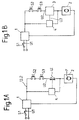
- FIG. 1b shows a block diagram of an electronic safety circuit which is operated with line voltage U1. Doing so in turn the mains voltage U1 is fed to a power supply unit 1 via a main switch S1.
- the power supply unit 1 converts the mains voltage U1 into a rectified supply voltage U2 for the downstream stages.
- the supply voltage U2 in turn passes through two safety switches S2, S3 to a switching stage 3 and a motor stage 2, which are arranged one behind the other in series.
- Switching stage 3 has a semiconductor switch, and operation of motor stage 2 is not possible if the semiconductor switch or the safety switches S2, S3 are open.
- the safety switches S2, S3 are opened, for example, when the lid of the food processor is opened.
- the household appliance can be, for example, a mixer or juicer, a citrus juicer or the like. For safety reasons, two safety switches S2, S3 are often prescribed.
- the switching stage 3 is connected via a control line to a control stage 4, to which the supply voltage U2 is also supplied.
- Control stage 4 detects the operating state of switching stage 3 or safety switches S2, S3 via the control line. If the control stage 4 detects that the safety switches S2, S3 have been opened, the control stage 4 prevents the further operation of the motor stage 2 via the switch stage 3. That is, the non-operation of the switch stage 3 is blocked by the control stage 4. The non-operating state of the switching stage 3 is maintained until the control stage 4 detects the interruption of the power supply by means of the switch S1.
- the control stage 4 detects the interruption of the power supply by connecting it to the supply voltage U2. By interrupting the power supply, control stage 4 is reset to the inactive operating state.
- control stage 4 can also be reset by an additional reset button which is located on the Control level 4 attacks directly and only affects their function.
- the reset button can be formed in the supply line, which connects the supply voltage U2 to the control stage 4.
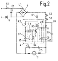
- the power supply unit 1 in FIG. 1A in FIG. 2 consists of a full-wave rectifier bridge 5, a PCT resistor 6 and a capacitor C1.
- the positive supply voltage U2 is supplied from the rectifier bridge 5 via the two safety switches S2, S3 to a thyristor 8 as a semiconductor switch and the motor stage 2 connected in series.
- Motor stage 2 has a motor 7 and interference suppression capacitors C5, C6.
- a capacitor C4 is connected, which serves as overvoltage protection against the voltages which cause the inductances of the motor 7 when switching on and off.
- the control terminal of the thyristor 8 is also connected to the supply voltage U2 via resistors R1, R5.
- a capacitor C3 is provided between the control connection and the cathode of the thyristor 8.
- the capacitor C3 forms, together with the resistor R5, a timing element 11, which is referred to below as the second timing element.
- the second timing element 11 causes the thyristor 8 to be fired with a slight delay after the main switch S1 has been actuated.
- the main switch S1 is closed at the time t0, the mains voltage U1 is supplied (FIG. 3). If the two safety switches S2, S3 are closed at the same time (FIG. 3b), the control connection of the thyristor 8 is delayed somewhat at the time t1, the control voltage U3 (FIG. 3c) is supplied after an e-function (not shown). Due to the delayed rise in control voltage U3, thyristor 8 ignites at time t2 (FIG. 3d - corresponds to current flow through thyristor). The second timer 11 causes the thyristor 8 not to supply the motor 7 with current immediately when the main switch S1 is switched on. This results in a smoother and bounce-free start-up of the motor 7.
- the thyristor 8 which has been switched through remains in the switched-through state independently of the control voltage U3 which is fed in further.
- the switched-through state is also maintained when the control voltage U3 drops to 0 with respect to the cathode.
- the capacitor C4 also has the function of a filter capacitor, which also maintains the current flow through the thyristor 8 even when the half-wave pulses supplied by the full-wave rectifier bridge 5 go to 0 in a 100 Hz rhythm.
- the current flow through the ignited thyristor 8 can only be interrupted by opening one of the two safety switches S2, S3. This is shown in FIG. 3 at time t3. The current flow (FIG. 3e) through the thyristor 8 is thus interrupted.
- the control stage 4 from FIG. 1B is supplied with the supply voltage U2 via the resistor R1.
- the control stage 4 has a transistor 9, the collector resistance of which simultaneously forms the resistor R5 of the second timing element 11. That is, the control terminal of the thyristor 8 is connected to the collector of the NPN transistor 9.
- the resistor R1 mainly acts as a voltage divider in order to lower the supply voltage for the control electrode of the thyristor 8 and the control stage 4 compared to the supply voltage 2.
- the reduced supply voltage passes through a resistor R2 and another Resistor R3 to the base of transistor 9.
- the emitter of transistor 9 is connected to the cathode of thyristor 8 or to the motor connection and not directly to the minus connection of rectifier 5.
- the internal ohmic resistance of the motor 7 simultaneously acts as a voltage divider to reduce the supply voltage for the control stage 4.
- the transistor 9 of the control stage 4 described so far would switch on immediately when the main switch S1 is switched on at the time t0.
- the control connection of the thyristor 8 would thus be immediately connected to the cathode of the thyristor 8 via the collector-emitter path of the transistor 9. Switching thyristor 8 through would then no longer be ensured.
- a further timer 10 is therefore provided, which is formed from the resistor R2 and a capacitor C2.
- the timing element 10 (hereinafter referred to as the first timing element) has a larger time constant than the second timing element 11, which was described above.
- the different time constants ensure that the thyristor 8 switches through safely before the transistor 9. If the thyristor 8 has switched through, the level of the control voltage U3 can no longer influence the operating state of the thyristor 8. The thyristor 8 remains ignited, even if the transistor 9 brings the control voltage U3 to the potential of the thyristor cathode at the time t3 due to the first timing element 10. Consequently, the control stage 4 no longer has any influence on the fired state of the thyristor 8.
- the current flow through the motor or through the fired thyristor 8 at time t4 can only be interrupted by opening the safety switches S2, S3.
- the opening of the safety switches S2, S3 has on the switched through State of the transistor 9 has no influence, which is why the control voltage U3 remains at thyristor cathode potential.
- a renewed closing of the safety switches S2, S3 at the time t5 cannot cause the thyristor 8 to re-ignite because the control voltage U3 is still below the ignition threshold.
- the emitter line In order to cancel the switched-on state of the transistor 9, the emitter line must be interrupted, for example, by a reset button (not shown).
- the emitter line must remain interrupted until the thyristor 8 reaches the ignition voltage potential via the resistor branch R1, R5 and due to the time delay caused by the capacitor C3.
- the reset button can also be dispensed with if the main switch S1 is actuated. If the main switch S1 is actuated at time t6 and briefly interrupted, the capacitor C2 of the first timing element 10 is safely discharged via a resistance branch R3, R4 serving as a discharge circuit 12.
- the resistor R4 is connected between the base and emitter of the transistor 9. No resistor is arranged in the emitter branch of the transistor 9, which is why the capacitor C2 can additionally be discharged via the base emitter path.
- the described electronic safety circuit can also be combined with a phase control (not shown) to regulate the engine speed.
Landscapes
- Engineering & Computer Science (AREA)
- Mechanical Engineering (AREA)
- Food Science & Technology (AREA)
- General Engineering & Computer Science (AREA)
- Food-Manufacturing Devices (AREA)
- Cookers (AREA)
- Electric Stoves And Ranges (AREA)
- Building Awnings And Sunshades (AREA)
- Supports For Plants (AREA)
- Centrifugal Separators (AREA)
Claims (14)
- Circuit de sécurité pour un appareil électroménager constitué de plusieurs composants reliés l'un à l'autre de façon amovible et entraîné par un moteur électrique (7) qui, en plus d'un interrupteur principal S1 pour sa mise en route, présente un ou plusieurs interrupteurs de sécurité (S2, S3) montés électriquement en série qui ne permettent que si tous les composants se trouvent à leur place réglementaire, garantissant la sécurité de l'utilisateur, que le moteur électrique (7), l'interrupteur principal (S1) étant fermé, accède à sa tension d'alimentation et puisse donc être utilisé, circuit dans lequel il existe des moyens (R, 8), manoeuvrés par voie électrique ou électronique, qui font en sorte que, si, le moteur électrique (7) étant en marche en soi, sa tension d'alimentation (U2) est interrompue après que l'un des composants de l'appareil électroménager ait quitté sa place réglementaire, il n'est possible de faire démarrer à nouveau le moteur électrique (7) que par le moyen que d'une part tous les composants de l'appareil ménager sont à nouveau mis à leur place réglementaire par l'utilisateur et que d'autre part l'utilisateur ouvre l'interrupteur principal (S1) puis ensuite le ferme à nouveau,
caractérisé par le fait que les moyens sont constitués d'un relais (R) et d'un coupe-circuit (U) manoeuvré par ce relais et fermé à l'état inactif, que le relais (R) est d'une part monté en série avec le moteur électrique (7) et d'autre part shunté par un dispositif qui est monté électriquement en parallèle avec lui et qui, de son côté, contient, dans un circuit de série électrique au moins un interrupteur de sécurité (S2, S3) et le coupe-circuit (U), les impédances du relais (R), du moteur électrique (7) et du dispositif étant accordées l'une sur l'autre de façon que, le coupe-circuit (U) étant fermé et les interrupteurs de sécurité (S2, S3) étant fermés, le courant d'alimentation du moteur électrique (7) passe pratiquement exclusivement par le dispositif et non par le relais (R) et que, le dispositif faisant l'objet d'une coupure électrique, une proportion suffisamment importante de la tension d'alimentation totale arrive au relais (R) pour que celui-ci ouvre le coupe-circuit (U) et le maintienne dans sa position d'ouverture, mais que la tension arrivant au moteur électrique (7) ne suffise plus pour qu'il puisse marcher. - Circuit de sécurité selon le préambule de la revendication 1,
caractérisé par le fait que les moyens présentent un étage de commutation électronique (3) qui, en même temps qu'au moins un interrupteur de sécurité (S2, S3), est monté électriquement en série avec le moteur électrique (7) et que l'étage de commutation (3) présente un interrupteur à semiconducteur et qu'est prévu un étage de commande (4) qui commande l'étage de commutation (3) et, après ouverture de l'interrupteur de sécurité (2, 3), interdit le passage du courant par l'étage de commutation (3) jusqu'à ce que l'on manoeuvre une touche de réinitialisation. - Circuit de sécurité selon le préambule de la revendication 2,
caractérisé par le fait que l'étage de commutation (3) est un interrupteur à semiconducteur entraîné par des demi-ondes d'alimentation positives. - Circuit de sécurité selon le préambule de la revendication 3,
caractérisé par le fait que l'interrupteur à semiconducteur est un thyristor (8) parallèlement auquel est monté un condensateur (C4). - Circuit de sécurité selon le préambule de la revendication 4,
caractérisé par le fait que l'étage de commande (4) est constitué d'un transistor de commutation (9) et d'un premier élément de temporisation (10) qui est disposé dans la branche de la base et qui rend conducteur le transistor de commutation (9) avec un retard dans le temps par rapport au thyristor (8). - Circuit de sécurité selon le préambule de la revendication 5,
caractérisé par le fait qu'un condensateur (C3) est relié à la borne de commande du thyristor (8). - Circuit de sécurité électronique selon la revendication 6,
caractérisé par le fait que la borne de commande du thyristor (8) est reliée au collecteur du transistor de commutation (9). - Circuit de sécurité selon le préambule de la revendication 7,
caractérisé par le fait qu'avec la résistance (R5) de collecteur du transistor de commutation (9), le condensateur (C3) forme un second élément de temporisation (11) qui présente une constante de temps inférieure à celle du premier élément de temporisation (10). - Circuit de sécurité selon le préambule de la revendication 8,
caractérisé par le fait que la constante de temps du premier élément de temporisation (10) est de préférence à peu près trois fois plus grande que celle du second élément de temporisation (11). - Circuit de sécurité selon le préambule de la revendication 9,
caractérisé par le fait que la constante de temps du premier élément de temporisation (10) vaut de préférence environ 150 ms. - Circuit de sécurité selon le préambule de la revendication 10,
caractérisé par le fait que le premier élément de temporisation (10) est relié au circuit de décharge (12) placé dans la branche de base du transistor de commutation (9). - Circuit de sécurité selon le préambule de la revendication 1,1
caractérisé par le fait que le circuit de décharge (12) est constitué d'une première résistance (R3) qui relie le premier élément de temporisation (10) à la base du transistor de commutation (9) et d'une seconde résistance (4) qui se situe entre la base et l'émetteur du transistor de commutation (9). - Circuit de sécurité selon le préambule de la revendication 12,
caractérisé par le fait que la première résistance (R3) vaut environ 15 k Ω et que la seconde résistance (R4) vaut environ 10 kΩ. - Circuit de sécurité selon le préambule de la revendication 2,
caractérisé par le fait que la touche de réinitialisation est l'interrupteur principal (S1).
Applications Claiming Priority (2)
| Application Number | Priority Date | Filing Date | Title |
|---|---|---|---|
| DE3930885 | 1989-09-15 | ||
| DE3930885 | 1989-09-15 |
Publications (3)
| Publication Number | Publication Date |
|---|---|
| EP0417800A2 EP0417800A2 (fr) | 1991-03-20 |
| EP0417800A3 EP0417800A3 (en) | 1993-03-17 |
| EP0417800B1 true EP0417800B1 (fr) | 1996-02-21 |
Family
ID=6389530
Family Applications (1)
| Application Number | Title | Priority Date | Filing Date |
|---|---|---|---|
| EP90117686A Expired - Lifetime EP0417800B1 (fr) | 1989-09-15 | 1990-09-13 | Circuit électronique de sûreté pour un appareil électroménager commandé par un moteur électrique |
Country Status (4)
| Country | Link |
|---|---|
| EP (1) | EP0417800B1 (fr) |
| AT (1) | ATE134431T1 (fr) |
| DE (1) | DE59010145D1 (fr) |
| ES (1) | ES2083408T3 (fr) |
Cited By (1)
| Publication number | Priority date | Publication date | Assignee | Title |
|---|---|---|---|---|
| DE102005038919A1 (de) * | 2005-08-17 | 2007-03-15 | BSH Bosch und Siemens Hausgeräte GmbH | Elektromotorisches Küchengerät mit elektrischer oder elektronischer Verriegelung |
Families Citing this family (9)
| Publication number | Priority date | Publication date | Assignee | Title |
|---|---|---|---|---|
| DE19617882B4 (de) * | 1996-05-04 | 2005-08-11 | Metabowerke Gmbh | Elektromotorische Heckenschere mit Zweihandbedienung |
| DE19644435A1 (de) * | 1996-10-25 | 1998-05-07 | Kloeckner Moeller Gmbh | Mehrbereichs-Spannungsnetzteil |
| KR100233052B1 (ko) * | 1997-11-04 | 1999-12-01 | 윤종용 | 전자렌지의 전원공급회로 |
| US6609821B2 (en) | 2001-04-13 | 2003-08-26 | Sunbeam Products, Inc. | Blender base with food processor capabilities |
| WO2002102219A1 (fr) * | 2001-06-20 | 2002-12-27 | Koninklijke Philips Electronics N.V. | Appareil dote d'un dispositif de securite |
| DE10222376A1 (de) * | 2002-05-21 | 2003-12-04 | Vorwerk Co Interholding | Elektromotorisch betriebenes Küchengerät |
| EP2378380B1 (fr) * | 2010-04-16 | 2012-12-12 | Siemens Aktiengesellschaft | Dispositif de raccordement pour appareils de terrain et procédé de fonctionnement |
| ES2348529B1 (es) * | 2010-05-03 | 2011-12-13 | Manuel Dominguez Lopez | Batidora de cocina. |
| CN112315347B (zh) * | 2020-11-09 | 2023-08-11 | 中山市惠尔普斯电器有限公司 | 一种安全可靠的食品料理机 |
Family Cites Families (4)
| Publication number | Priority date | Publication date | Assignee | Title |
|---|---|---|---|---|
| US4111372A (en) * | 1977-04-25 | 1978-09-05 | General Electric Company | Food processor interlock |
| DE3311291A1 (de) * | 1983-03-28 | 1984-10-04 | Braun Ag, 6000 Frankfurt | Magnetische sicherheitsvorrichtung, insbesondere fuer ein kuechengeraet |
| EP0129222A3 (fr) * | 1983-06-17 | 1987-11-04 | Moulinex S.A. | Dispositif de commande d'un appareil électroménager |
| DE3540370A1 (de) * | 1985-11-14 | 1987-05-21 | Braun Ag | Sicherheitsvorrichtung fuer kuechengeraete |
-
1990
- 1990-09-13 AT AT90117686T patent/ATE134431T1/de not_active IP Right Cessation
- 1990-09-13 DE DE59010145T patent/DE59010145D1/de not_active Expired - Fee Related
- 1990-09-13 ES ES90117686T patent/ES2083408T3/es not_active Expired - Lifetime
- 1990-09-13 EP EP90117686A patent/EP0417800B1/fr not_active Expired - Lifetime
Cited By (1)
| Publication number | Priority date | Publication date | Assignee | Title |
|---|---|---|---|---|
| DE102005038919A1 (de) * | 2005-08-17 | 2007-03-15 | BSH Bosch und Siemens Hausgeräte GmbH | Elektromotorisches Küchengerät mit elektrischer oder elektronischer Verriegelung |
Also Published As
| Publication number | Publication date |
|---|---|
| EP0417800A3 (en) | 1993-03-17 |
| ES2083408T3 (es) | 1996-04-16 |
| DE59010145D1 (de) | 1996-03-28 |
| EP0417800A2 (fr) | 1991-03-20 |
| ATE134431T1 (de) | 1996-03-15 |
Similar Documents
| Publication | Publication Date | Title |
|---|---|---|
| DE10156198B4 (de) | Filter zur Vermeidung einer Netz-Rückwirkung in Form elektrischer Störsignale | |
| EP0417800B1 (fr) | Circuit électronique de sûreté pour un appareil électroménager commandé par un moteur électrique | |
| EP0048793B1 (fr) | Suppresseur de démarrage d'appareils électriques après une panne de courant | |
| DE2001580A1 (de) | Kurzschluss-Beseitigungseinrichtung fuer Schaltvorrichtungen in Stromversorgungsschaltungen | |
| EP0035225B1 (fr) | Commutateur de proximitié avec ses dispositifs de surveillance | |
| DE3032790A1 (de) | Motorschutzschaltung | |
| DE3010087A1 (de) | Kuechengeraet | |
| DE3737712C2 (fr) | ||
| EP2539912A1 (fr) | Configuration de circuit pour faire fonctionner un appareil électroménager, et procédé correspondant | |
| DE19803746C2 (de) | Stromversorgungsschaltung für einen Mikrowellenofen | |
| DE19751674C2 (de) | Schaltungsanordnung mit Sicherheitsfunktion | |
| DE3720928A1 (de) | Haushaltsgeraet, insbesondere entsafter | |
| DE3119794A1 (de) | Schutzschaltung fuer einen phasenanschnittgesteuerten oder -geregelten elektromotor | |
| EP0312779B1 (fr) | Circuit de commande électrique pour table et/ou armoire installées contre un mur vertical | |
| DE3233516C2 (fr) | ||
| EP0085202B1 (fr) | Commutateur de protection | |
| DE4445207C2 (de) | Schaltungsanordnung für eine elektrisch beheizte Kaffeemaschine | |
| DE3619552C2 (fr) | ||
| DE69909384T2 (de) | Mikrowellenherd : das Betrieb des Anzugsstroms | |
| DE69829292T2 (de) | Vorrichtung und verfahren zum abschalten der versorgungsspannung einer last, und damit ausgerüstetes elektrisches gerät | |
| WO2007025967A1 (fr) | Circuit de commande destine a faire fonctionner un transformateur electronique | |
| EP0463687A2 (fr) | Montage de commande de puissance à faible rétroaction vers le secteur | |
| DE3516900A1 (de) | Schaltungsanordnung zum sicheren ruecksetzen und starten eines mikroprozessors | |
| DE3510496A1 (de) | Anlassvorrichtung mit sterndreiecksschaltung fuer drehstrominduktionsmotor | |
| DE19958039C2 (de) | Vorrichtung und Verfahren zur Vermeidung von Strom- und Spannungsspitzen |
Legal Events
| Date | Code | Title | Description |
|---|---|---|---|
| PUAI | Public reference made under article 153(3) epc to a published international application that has entered the european phase |
Free format text: ORIGINAL CODE: 0009012 |
|
| AK | Designated contracting states |
Kind code of ref document: A2 Designated state(s): AT CH DE ES FR IT LI |
|
| PUAL | Search report despatched |
Free format text: ORIGINAL CODE: 0009013 |
|
| AK | Designated contracting states |
Kind code of ref document: A3 Designated state(s): AT CH DE ES FR IT LI |
|
| 17P | Request for examination filed |
Effective date: 19930217 |
|
| 17Q | First examination report despatched |
Effective date: 19940826 |
|
| RAP1 | Party data changed (applicant data changed or rights of an application transferred) |
Owner name: BRAUN AKTIENGESELLSCHAFT |
|
| GRAA | (expected) grant |
Free format text: ORIGINAL CODE: 0009210 |
|
| AK | Designated contracting states |
Kind code of ref document: B1 Designated state(s): AT CH DE ES FR IT LI |
|
| PG25 | Lapsed in a contracting state [announced via postgrant information from national office to epo] |
Ref country code: IT Free format text: LAPSE BECAUSE OF FAILURE TO SUBMIT A TRANSLATION OF THE DESCRIPTION OR TO PAY THE FEE WITHIN THE PRE;WARNING: LAPSES OF ITALIAN PATENTS WITH EFFECTIVE DATE BEFORE 2007 MAY HAVE OCCURRED AT ANY TIME BEFORE 2007. THE CORRECT EFFECTIVE DATE MAY BE DIFFERENT FROM THE ONE RECORDED.SCRIBED TIME-LIMIT Effective date: 19960221 |
|
| REF | Corresponds to: |
Ref document number: 134431 Country of ref document: AT Date of ref document: 19960315 Kind code of ref document: T |
|
| REF | Corresponds to: |
Ref document number: 59010145 Country of ref document: DE Date of ref document: 19960328 |
|
| REG | Reference to a national code |
Ref country code: CH Ref legal event code: NV Representative=s name: PATENTANWALTSBUREAU BOSSHARD UND LUCHS |
|
| REG | Reference to a national code |
Ref country code: ES Ref legal event code: FG2A Ref document number: 2083408 Country of ref document: ES Kind code of ref document: T3 |
|
| ET | Fr: translation filed | ||
| PGFP | Annual fee paid to national office [announced via postgrant information from national office to epo] |
Ref country code: AT Payment date: 19960913 Year of fee payment: 7 |
|
| PGFP | Annual fee paid to national office [announced via postgrant information from national office to epo] |
Ref country code: CH Payment date: 19961025 Year of fee payment: 7 |
|
| PLBE | No opposition filed within time limit |
Free format text: ORIGINAL CODE: 0009261 |
|
| STAA | Information on the status of an ep patent application or granted ep patent |
Free format text: STATUS: NO OPPOSITION FILED WITHIN TIME LIMIT |
|
| 26N | No opposition filed | ||
| PGFP | Annual fee paid to national office [announced via postgrant information from national office to epo] |
Ref country code: DE Payment date: 19970822 Year of fee payment: 8 |
|
| PG25 | Lapsed in a contracting state [announced via postgrant information from national office to epo] |
Ref country code: AT Free format text: LAPSE BECAUSE OF NON-PAYMENT OF DUE FEES Effective date: 19970913 |
|
| PGFP | Annual fee paid to national office [announced via postgrant information from national office to epo] |
Ref country code: FR Payment date: 19970917 Year of fee payment: 8 |
|
| PGFP | Annual fee paid to national office [announced via postgrant information from national office to epo] |
Ref country code: ES Payment date: 19970919 Year of fee payment: 8 |
|
| PG25 | Lapsed in a contracting state [announced via postgrant information from national office to epo] |
Ref country code: CH Free format text: LAPSE BECAUSE OF NON-PAYMENT OF DUE FEES Effective date: 19970930 Ref country code: LI Free format text: LAPSE BECAUSE OF NON-PAYMENT OF DUE FEES Effective date: 19970930 |
|
| REG | Reference to a national code |
Ref country code: CH Ref legal event code: PL |
|
| PG25 | Lapsed in a contracting state [announced via postgrant information from national office to epo] |
Ref country code: ES Free format text: LAPSE BECAUSE OF THE APPLICANT RENOUNCES Effective date: 19980914 |
|
| PG25 | Lapsed in a contracting state [announced via postgrant information from national office to epo] |
Ref country code: FR Free format text: LAPSE BECAUSE OF NON-PAYMENT OF DUE FEES Effective date: 19990531 |
|
| PG25 | Lapsed in a contracting state [announced via postgrant information from national office to epo] |
Ref country code: DE Free format text: LAPSE BECAUSE OF NON-PAYMENT OF DUE FEES Effective date: 19990701 |
|
| REG | Reference to a national code |
Ref country code: FR Ref legal event code: ST |
|
| REG | Reference to a national code |
Ref country code: ES Ref legal event code: FD2A Effective date: 20001102 |