EP0417362B1 - Daten/Faksimile-Fernsprechgerät mit einer elektrophoretischen Anzeige - Google Patents
Daten/Faksimile-Fernsprechgerät mit einer elektrophoretischen Anzeige Download PDFInfo
- Publication number
- EP0417362B1 EP0417362B1 EP89309376A EP89309376A EP0417362B1 EP 0417362 B1 EP0417362 B1 EP 0417362B1 EP 89309376 A EP89309376 A EP 89309376A EP 89309376 A EP89309376 A EP 89309376A EP 0417362 B1 EP0417362 B1 EP 0417362B1
- Authority
- EP
- European Patent Office
- Prior art keywords
- display
- telephone
- coupled
- data
- microprocessor
- Prior art date
- Legal status (The legal status is an assumption and is not a legal conclusion. Google has not performed a legal analysis and makes no representation as to the accuracy of the status listed.)
- Expired - Lifetime
Links
Images


Classifications
-
- H—ELECTRICITY
- H04—ELECTRIC COMMUNICATION TECHNIQUE
- H04N—PICTORIAL COMMUNICATION, e.g. TELEVISION
- H04N1/00—Scanning, transmission or reproduction of documents or the like, e.g. facsimile transmission; Details thereof
- H04N1/0035—User-machine interface; Control console
- H04N1/00352—Input means
- H04N1/00384—Key input means, e.g. buttons or keypads
-
- H—ELECTRICITY
- H04—ELECTRIC COMMUNICATION TECHNIQUE
- H04M—TELEPHONIC COMMUNICATION
- H04M1/00—Substation equipment, e.g. for use by subscribers
- H04M1/02—Constructional features of telephone sets
- H04M1/23—Construction or mounting of dials or of equivalent devices; Means for facilitating the use thereof
-
- H—ELECTRICITY
- H04—ELECTRIC COMMUNICATION TECHNIQUE
- H04M—TELEPHONIC COMMUNICATION
- H04M1/00—Substation equipment, e.g. for use by subscribers
- H04M1/247—Telephone sets including user guidance or feature selection means facilitating their use
-
- H—ELECTRICITY
- H04—ELECTRIC COMMUNICATION TECHNIQUE
- H04M—TELEPHONIC COMMUNICATION
- H04M1/00—Substation equipment, e.g. for use by subscribers
- H04M1/26—Devices for calling a subscriber
- H04M1/27—Devices whereby a plurality of signals may be stored simultaneously
- H04M1/274—Devices whereby a plurality of signals may be stored simultaneously with provision for storing more than one subscriber number at a time, e.g. using toothed disc
- H04M1/2745—Devices whereby a plurality of signals may be stored simultaneously with provision for storing more than one subscriber number at a time, e.g. using toothed disc using static electronic memories, e.g. chips
- H04M1/27467—Methods of retrieving data
- H04M1/27475—Methods of retrieving data using interactive graphical means or pictorial representations
-
- H—ELECTRICITY
- H04—ELECTRIC COMMUNICATION TECHNIQUE
- H04M—TELEPHONIC COMMUNICATION
- H04M1/00—Substation equipment, e.g. for use by subscribers
- H04M1/66—Substation equipment, e.g. for use by subscribers with means for preventing unauthorised or fraudulent calling
- H04M1/667—Preventing unauthorised calls from a telephone set
- H04M1/67—Preventing unauthorised calls from a telephone set by electronic means
- H04M1/673—Preventing unauthorised calls from a telephone set by electronic means the user being required to key in a code
-
- H—ELECTRICITY
- H04—ELECTRIC COMMUNICATION TECHNIQUE
- H04M—TELEPHONIC COMMUNICATION
- H04M11/00—Telephonic communication systems specially adapted for combination with other electrical systems
- H04M11/06—Simultaneous speech and data transmission, e.g. telegraphic transmission over the same conductors
- H04M11/066—Telephone sets adapted for data transmision
-
- H—ELECTRICITY
- H04—ELECTRIC COMMUNICATION TECHNIQUE
- H04N—PICTORIAL COMMUNICATION, e.g. TELEVISION
- H04N1/00—Scanning, transmission or reproduction of documents or the like, e.g. facsimile transmission; Details thereof
- H04N1/0035—User-machine interface; Control console
-
- H—ELECTRICITY
- H04—ELECTRIC COMMUNICATION TECHNIQUE
- H04N—PICTORIAL COMMUNICATION, e.g. TELEVISION
- H04N1/00—Scanning, transmission or reproduction of documents or the like, e.g. facsimile transmission; Details thereof
- H04N1/0035—User-machine interface; Control console
- H04N1/00405—Output means
- H04N1/00408—Display of information to the user, e.g. menus
- H04N1/00411—Display of information to the user, e.g. menus the display also being used for user input, e.g. touch screen
-
- H—ELECTRICITY
- H04—ELECTRIC COMMUNICATION TECHNIQUE
- H04M—TELEPHONIC COMMUNICATION
- H04M1/00—Substation equipment, e.g. for use by subscribers
- H04M1/02—Constructional features of telephone sets
- H04M1/0295—Mechanical mounting details of display modules
-
- H—ELECTRICITY
- H04—ELECTRIC COMMUNICATION TECHNIQUE
- H04M—TELEPHONIC COMMUNICATION
- H04M1/00—Substation equipment, e.g. for use by subscribers
- H04M1/247—Telephone sets including user guidance or feature selection means facilitating their use
- H04M1/2478—Telephone terminals specially adapted for non-voice services, e.g. email, internet access
-
- H—ELECTRICITY
- H04—ELECTRIC COMMUNICATION TECHNIQUE
- H04M—TELEPHONIC COMMUNICATION
- H04M2250/00—Details of telephonic subscriber devices
- H04M2250/22—Details of telephonic subscriber devices including a touch pad, a touch sensor or a touch detector
-
- Y—GENERAL TAGGING OF NEW TECHNOLOGICAL DEVELOPMENTS; GENERAL TAGGING OF CROSS-SECTIONAL TECHNOLOGIES SPANNING OVER SEVERAL SECTIONS OF THE IPC; TECHNICAL SUBJECTS COVERED BY FORMER USPC CROSS-REFERENCE ART COLLECTIONS [XRACs] AND DIGESTS
- Y10—TECHNICAL SUBJECTS COVERED BY FORMER USPC
- Y10S—TECHNICAL SUBJECTS COVERED BY FORMER USPC CROSS-REFERENCE ART COLLECTIONS [XRACs] AND DIGESTS
- Y10S379/00—Telephonic communications
- Y10S379/916—Touch screen associated with telephone set
Definitions
- This invention relates generally to a telephone subset and more particularly to a data/facsimile telephone subset which employs a high resolution electrophoretic display.
- a plurality of horizontal lines which are positioned above the vertical lines and insulated therefrom by a thin insulating layer at each of the intersection points.
- a conductive plate Spaced above the horizontal and vertical line pattern is a conductive plate.
- the space between the conductive plate and the X and Y line patterns is filled in with an electrophoretic dispersion containing chargeable pigment particles.
- pigment particles which are located in wells or depressions between the X and Y pattern, are caused to migrate towards the conductive plate and are deposited upon the conductive plate in accordance with the bias applied to the X and Y line conductors.
- electrophoretic dispersions which are suitable for operating with the display, as well as techniques for fabricating the display. In this manner such displays can be fabricated to contain large effective display surfaces while being relatively thin and which are capable of high resolution at very low power.
- Prior art telephone subset systems which incorporate a display panel are known in the art. Such a system is disclosed in an article entitled "An Interactive Touch Phone for Office Automation” appearing in Vol. 23, No. 2 of IEEE Communications Magazine (February 1985).
- the system disclosed therein includes a low resolution display panel, a telephone handset, a microprocessor operative to cause the panel to display a graphical representation of a telephone keyboard, and a position sensitive means positioned on the display which is operative to produce a telephone number output signal when accessed by a user employing the graphical representation as a guide.
- a position sensitive means positioned on the display which is operative to produce a telephone number output signal when accessed by a user employing the graphical representation as a guide.
- PCT Application WO 88/00371, published January 14, 1988 and entitled PERIPHERAL CONTROLLER also teaches that a plurality of graphic keyboard presentations corresponding to telephone dialing menus and the like can be displayed on a touch sensitive keypad display means. This system, however, also fails to teach the use of a random keypad presentation in order to prevent unauthorised persons from observing the numbers entered thereby.
- U.K. Patent Application 2,156,186A to Laube published Oct. 2, 1985 and entitled COMMUNICATION TERMINAL, teaches a videotex graphics data transmission system which includes a flat panel display screen having a transparent electrically conductive overlay, a microprocessor and an interface means for coupling the display panel to a telephone line.
- the display provides a telephone dialing keypad whereby the user can dial a number and transmit or receive videotex graphic data. Laube does not, however, address the issue of unauthorised access to the number being dialed by the user.
- a telephone subset apparatus for use in providing high quality data displays, comprising a telephone subset including a housing having a telephone handset coupled thereto, a high resolution display panel means mounted on said top surface of said housing and capable of being accessed by an X-Y addressing means to display graphic data in a plurality of lines, microprocessor means coupled to said display panel and operative to cause said panel to provide a graphic presentation of a telephone keyboard arrangement according to said X-Y addressing means, position sensitive means coupled to said panel and operative when accessed to produce a telephone number output signal as dialed by a user employing said graphic keyboard presentation as a guide for selecting said number.
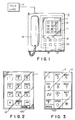
- FIG. 1 is a top plan view of a telephone subset having an electrophoretic display according to this invention.
- FIG. 2 is a diagram depicting a particular type of graphic keyboard format which can be employed in conjunction with the subset of FIG. 1.
- FIG. 3 is a schematic diagram depicting another type of graphic keyboard format.
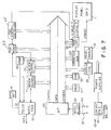
- FIG. 4 is a block diagram showing a telephone subset operating in conjunction with a display according to this invention.
- FIG. 5 is a diagram depicting another type of display which can be employed with this invention.
- FIG. 6 is a detailed block diagram depicting the operation of the subset according to this invention.
- FIG. 7 is a system schematic diagram showing the use of the telephone subset in both a data and telephone mode.
- a telephone subset 10 which includes a handset 14 normally including a transmitter and receiver portion.
- the entire mechanism for the subset, including the transmitter and receiving portion, as well as the various circuitry to activate ringing and so on, are well known functions and are available with many different subsets of the prior art.
- the subset 10 as including the above components is an operational telephone which can be directly connected to a telephone line 13.
- the subset 10 has located on the front surface thereof an electrophoretic display 11.
- the display 11 may be fairly large in effective area and, for example, may be four inches by four inches or more. It is, of course, understood that the display 11 can be rectangular, square or of any geometrical configuration of adequate size.
- the electrophoretic display 11 is accessed, as indicated above, by means of an XY matrix and is capable of providing high resolution with a relatively large number of data lines.
- the display 11 is associated with an overlay 12.
- the overlay 12 may be a pressure or position sensitive device which, as will be explained, enables the user of the subset to implement the dialing sequence when a call is to be made.
- mode key switches or momentary push buttons are utilized to implement operating modes associated with the subset employing the high resolution electrophoretic display 11.
- the key switches can also be directly displayed on the display 11 and operate with the overlay 12 as compared to discrete keys. Hence, one such key 100 is shown by way of example in FIGS. 2 and 3. Therefore, the entire top surface of the subset housing can be a display panel only (dashed line of FIG. 1).
- the main aspect of using the display 11 in conjunction with the subset 10 is to enable a user to dial various numbers and to receive data from called locations, which data can be read directly from the display. In this manner the user can utilize the subset 10 as a means for receiving graphical data or other data from various remote locations which data will be immediately displayed on the display 11 associated with the subset. It is, of course, apparent that apart from receiving data one must be able to initiate a call and utilize the subset 10 as a conventional telephone.
- FIG. 1 there is displayed on the subset, via the display 11, a replica of a conventional dialing keyboard. More particularly, FIG. 2 shows the conventional keyboard.
- this keyboard format is generated by a microprocessor means utilizing CAD techniques whereby when a subscriber goes off hook the keyboard format is displayed.
- the pressure or position sensitive overlay 12 the user can now dial in any number desired.
- a pressure sensitive overlay is described, there are many other techniques which will allow a touch overlay or touch operation, such as LED arrays or capacitive sensing devices. These devices will detect the position or pressure imparted by a user at various areas of the display, and hence, such an overlay is not directed solely to pressure.
- pressure overlays are furnished by many companies and are conventional components. See, for example, a product distributed by Tektronix Inc. of Beaverton, Oregon, which product is marketed as an interactive touch panel. The panel essentially is capable of detecting touch or pressure with high resolution. It is rugged and reliable and of relatively low cost. Other companies, such as Hewlett Packard of California, produce systems which are designated as touch screen systems. Thus, as one can ascertain, there are many overlays, as overlay 12, which can be associated with various display panels to enable a user to implement a code or other sequence by touching an area of a screen which has been displayed.
- FIG. 2 there is shown a typical telephone keyboard format which, as will be explained, is presented on the display 11 and which immediately becomes visible to the user.
- the user can essentially place a call by accessing the various display areas which will produce discrete signals generated by touching the various positions to enable a user to dial in a conventional manner.
- FIG. 2 shows the conventional telephone keyboard of which we are all apprised of.
- This keyboard format is generated by a microprocessor whereby when a subscriber goes off hook or desires to place a call, the keyboard format, as shown in FIG. 2, would be displayed.
- FIG. 3 there is shown another replica of a telephone keyboard.
- the numbers as for example compared to FIG. 2, are out of order or out of sequence.
- the ability to generate a graphic keyboard format on a display, as electrophoretic display 11, enables one to easily exchange the various positions associated with a conventional keyboard.
- the display 11 can generate a random format indicative of a telephone keyboard where the user can view the format and dial a number in complete secrecy. This aspect can, therefore, enable high security dialing.
- FIG. 2 shows a completely conventional keyboard which is generated and displayed on the electrophoretic display 11, while FIG. 3 shows a random arrangement of another keyboard format which can also be utilized to generate dialing pulses indicative of a telephone call.
- the display is effectively capable of displaying a plurality of stored numbers, including the name of the individual or company associated with that number.
- a cursor (FIG. 5) is also presented whereby the cursor can move along the listing and when the subscriber moves the cursor to the number he desires to call he can now activate or access the call by pressing a further button, such as button 21 on the subset.
- button 21 When the cursor is aligned at a particular telephone number the activation of button 21 causes the telephone circuitry to automatically dial the number at the cursor position. This, therefore, enables one to store hundreds of telephone numbers in local memory and to display all numbers stored. Then, by means of the cursor, the subscriber can select any one of the numbers stored and thereby immediately commence dialing.
- the user can rapidly scan the directory, or the telephone numbers as stored, by means of additional keys such as 17 and 18 and, hence, have rapid access to all numbers which are stored and displayed on the electrophoretic display 11 in order to initiate a dialing sequence or, for example, to look up or determine a certain number.
- additional keys such as 17 and 18
- the use of a high resolution, multiline display in conjunction with a subset will enable a user to access a large number of telephone numbers or other data.
- each number will be associated with a particular company or individual to thereby enable such a user to commence a rapid dialing sequence without any further access to the telephone keyboard.
- the directory consists of multiple data pages where each page can be addressed by means of a mode key on the subset. Hence, a listing of hundreds of telephone numbers displayed as 50 or more at one time is accommodated.
- the telephone subset includes a controller or microprocessor 25.
- microprocessors As one can ascertain, in today's technology there are many very powerful microprocessors which are commercially available. Certain microprocessors, for example, are capable of processing 32 bit words and are manufactured by many companies. See, for example, the microprocessor manufactured by Intel, Inc. as the 80386. The Motorola Corporation manufactures a microprocessor designated as the 68020 while the Zilog Company manufactures a microprocessor designated as the Z80000CPU.
- suitable microprocessors reference is made to a text entitled "32-bit Microprocessors" by H.J. Mitchell, published by the McGraw Hill Book Company (1986). In that text there is not only shown the structure of such microprocessors or controllers 25 but many of the applications associated with such devices.
- the microprocessor or controller 25 is coupled to a mode selector module 26 which mode selector module interfaces with certain of the buttons or keys, as 15-20, associated with the telephone subset of FIG. 1.
- the mode selector 26, as will be further explained, can be implemented by programming the microprocessor in a well known manner.
- the microprocessor 25 is typically associated with a random access memory or RAM 26 and a read only memory or ROM 27.
- RAM 26 Stored in the ROM are XY patterns indicative of a particular keyboard format, such as the keyboard shown in FIGS. 2 or 3 as well as others.
- the output of the ROM and RAM are coupled to a keyboard display module 30 which, essentially, controls an X decode and driver module 31 and a Y decode and driver module 32.
- the display 11 which is an electrophoretic display
- the display 11 is addressed by means of an XY matrix arrangement.
- This is a common access technique for many memory and display devices.
- the X and Y decode and driver modules 31 and 32 are coupled to suitable terminals of the electrophoretic display 11.
- XY addressing one can generate any type of display on the display 11 which will be visualized by the user.
- the user when the user implements a call he normally takes the handset 14 and places it in an off hook condition.
- This off hook condition is detected by means of an off hook detector 34 which, therefore, indicates to the controller or microprocessor 25 that a call is to be made.
- the controller 25 then accesses the suitable memory addresses of the ROM and RAM and displays the keyboard format shown in FIG. 2, for example.
- This is a conventional keyboard display.
- the keyboard format is, therefore, visually displayed to the user and, as indicated above, is associated with a position or pressure sensitive transparent overlay 12.
- the user then, by accessing the various areas of the display, can dial a number in a conventional manner. The exact dialing technique, and so on, will be explained subsequently.
- any event if the user desires a high security mode, in which a random keyboard portrayal is to be provided, he may then activate access button 20 informing the mode selector to activate a random generator sequence indicative of module 33.
- access button 20 informing the mode selector to activate a random generator sequence indicative of module 33.
- a certain number of keyboard formats can be directly stored in ROM memory 27 and, hence, the user would have access, for example, to five different keyboards and by pressing key 20 any one of the different five keyboard would randomly appear. In any event, this will again allow the user to commence a dialing sequence.
- Such a random generator format is associated with ROM and RAM memory locations to enable the keyboard display 30 to present the format shown in FIG. 3 or any other format.
- the dialing sequence is decoded by the dial decoder 50 which is controlled by the microprocessor 25 according to the displayed graphic keyboard format.
- the user will commence a dialing sequence which, essentially, would allow the telephone switching system to gain access to the dialed number.
- the system detects a ring back via the ring back detector 35 to thereby extinguish the display of the keyboard format to ready the subset display 11 for receiving data, if that is desired.
- the user can indicate this by pressing a save button also associated with the subset.
- a data display buffer 60 which will be explained.
- FIG. 6 shows a block diagram indicating the further implementation of the various features, as described above.
- the subset 10 may be associated with a pressure sensitive overlay 12 or any other type of touch or position overlay, as is well known in the art.
- the overlay 12 is coupled to a dial or TTMF generator 40 which includes dial decoder circuitry 50 of FIG. 1.
- the dial or TTMF generator 40 is a well known module and is available from many companies in integrated circuit form.
- the generator 40 converts the various switch positions associated with the display 11 to suitable frequencies or dial pulses to be transmitted over the telephone line 13 by means of conventional circuitry including the buffer or isolation amplifier 41.
- the dial or TTMF generator 40 includes a digit counter 42 coupled to the microprocessor 25 to determine each digit dialed for providing the proper timing.
- the telephone line is normally associated with a suitable buffer, which is available from many sources as well.
- the buffer 50 may contain storage and other suitable devices enabling one to transmit stored telephone numbers and thereby transmit the same over the conventional transmit or tip (TX) and receive or ring (RX) lines associated with the telephone line.
- the receive line RX is associated with a separate data buffer designated by reference numeral 60 and also shown in FIG. 1.
- the function of the data buffer 60 is to store incoming data and to direct the data to the RAM 26 or other memory sections of the microprocessor or controller 25. It is, of course, understood that such microprocessors can receive multiple inputs from various devices on real time input/output (I/O) buses.
- the microprocessor as programmed, will then determine the nature of the data, as stored in data buffer 60, in order to properly activate the keyboard display 11 to enable the display of the proper data and to decode the data according to the incoming data format. As indicated, and can be ascertained from the above referenced U.S. Pat. No.
- the electrophoretic display which has been described in U.S. Patent No. 4,655,897, is a high resolution display which does not require power for refreshing or storing data therein once the data is written.
- a display by utilizing such a display, one can now generate a visual presentation of a telephone keyboard to enable a user to dial any desired number in conjunction with a position sensitive transparent overlay. It is, of course, understood that the keyboard format can be changed according to the desires of a user.
- the telephone subset is now capable of storing a great many telephone numbers which can be displayed in terms of pages, for example, perhaps 10 or 50 telephone numbers on each page.
- the entire memory storage contents can be displayed and employed in conjunction with a movable cursor.
- the subscriber can now see each telephone number stored in memory and also knows the entity to which the telephone number belongs.
- By moving the cursor he can now select the telephone number he wishes to access and by merely pressing one of the subset keys can dial that number without ever accessing the displayed keyboard mode.
- the subscriber does not have to provide any individual or separate record of stored telephone numbers as is implemented in present day conventional telephone systems.
- the entire mechanism for operating in the directory mode is again implemented by pressing a mode key associated with the mode selector 26.
- the mode selector 26 for example, upon the depression of subset switch 15, will again inform the microprocessor 25 that it is desired to display all telephone numbers stored in memory.
- the microprocessor 25 will then access the RAM or ROM 26 and 27 and cause the stored data, indicative of stored telephone numbers, to be presented to the keyboard display 30 which is also under control of the microprocessor.
- the keyboard display 30 generates the various alphanumeric characters as including a character generator which will convert the stored digital data into analog numerals, as is well known in the prior art, and hence display telephone numbers on the electrophoretic display 11.
- a cursor is generated, which cursor can be moved along the directory display (FIG. 5) by means of additional subset buttons or keys.
- the cursor can be moved in an up or down direction as, for example, the cursor on a computer screen.
- Techniques for moving cursors to any location are well known. When the cursor is adjacent a desired number the user then merely presses a dial number key on the subset and the telephone number that the cursor is next to or aligned with, as shown in FIG. 5, is automatically dialed.
- the telephone subset of FIG. 1 also has an additional button or key which may be, for example, button 19.
- button 19 By pressing button 19 the telephone is now operated in a proprietary manner. For example, by depressing display button 19 the following sequence of events occur. The depression of button 19 informs the mode selector 26 to prompt the microprocessor 25 that a request is made to implement the generation of a keyboard display. The telephone user then dials in a four digit number, which is like a PIN number, as the same type of number as employed in conjunction with cash machines or credit card systems. The computer 25 compares the dialed in PIN number with a previously stored number and will indicate that the subscriber has access to confidential information contained in given memory locations of the read only memory 27.
- This information for example, would present, on the display 11, all credit card numbers which belong to the possessor of the secret code. This will, therefore, enable the user to place calls to enable him to order various goods by means of the telephone subset 10. In any event, he is provided with a separate display contained in a separate memory location of all his credit card numbers.
- the display also includes pertinent telephone numbers associated with those credit cards. For example, the number which he can call in regard to a missing or lost credit card, and so on. This data is easily stored in memory and, again, is accessible by means of the same techniques as described above.
- the above-noted system lends itself to furnishing a privacy phone lock.
- the operation would be as follows. With the handset 14 on hook, as shown in FIG. 1, the unit displays a simple array of characters which is not a keyboard format. These characters are stored in a reserved memory block and, essentially, are displayed on the electrophoretic display each time the handset is on hook. The electrophoretic display consumes no power once an array is written on the display. The user then must take the phone off hook and select a proper code via the characters displayed in the array to obtain a dial tone. Once the proper code is entered, a dial tone will be provided and the telephone keyboard display will be properly displayed. Otherwise no line connection can be made and one could not access the telephone line without having access to the code which may be implemented by means of the simple array of characters displayed on the display 11 when the hand set 14 is on hook.
- the telephone display 11 can also store and display a history of telephone usage, for example, the user code, the number dialed, the data, the time, the length of the call and so on.
- a history of telephone usage for example, the user code, the number dialed, the data, the time, the length of the call and so on.
- FIG. 7 there is shown a detailed block diagram showing a telephone subset 10, as described above, employing an electrophoretic display panel 11 which is employed for data and graphics display.
- FIG. 7 retains the same reference numerals as previously described in conjunction with the above-noted figures.
- the electrophoretic panel 11 which is coupled to X drive and Y drive circuits via panel control module designated as 31 and 32.
- the panel control is analogous to controls 31 and 32 of FIG. 4.
- the panel control is also coupled to a character generator 37 which essentially is coupled to the microprocessor 25 via a bidirectional address bus. Character generators for converting digital data into alphanumeric characters are also well known, as indicated in conjunction with FIG. 4, and can be implemented by the programming of the microprocessor 25.
- the entire subset normally interfaces with a conventional telephone line designated (PSTH) by means of a telephone interface 70, which is shown coupled to the handset 14 as part of subset 10.
- PSTH conventional telephone line designated
- the telephone interface may include the remaining telephone circuitry, as well as various other registers and so on for data operation.
- a separate facsimile modem 66 which is one of many different types of available modems capable of receiving various types of facsimile transmissions, such as groups I, II, III.
- Such modems for converting facsimile transmissions into graphic data are well known and coupled to the fax modem 66 is a fax graphics controller 68 which converts the facsimile transmissions into suitable graphics to be applied to the panel control circuit 31 and then displayed directly on the panel 11 associated with the subset.
- a modem control module 72 which is coupled to the fax modem 60 and which receives instructions from the control bus of the microprocessor 25 to enable proper operation.
- modem selector 71 which essentially is a conventional component and which determines the exact nature of the facsimile transmission to allow proper decoding.
- telephone apparatus can operate as a complete data subset whereby facsimile messages can be displayed directly on the display 11 and, for example, such a display can accommodate 500 or more lines of individual graphics, employing conventional facsimile modules and modems.
- the entire subset based on its use in conjunction with a high resolution display, has great capabilities and versatilities as should be apparent to those skilled in the art when reviewing the above-noted specification.
Landscapes
- Engineering & Computer Science (AREA)
- Signal Processing (AREA)
- Multimedia (AREA)
- Human Computer Interaction (AREA)
- Computer Security & Cryptography (AREA)
- Computer Networks & Wireless Communication (AREA)
- Computer Vision & Pattern Recognition (AREA)
- Control Of Indicators Other Than Cathode Ray Tubes (AREA)
Claims (21)
- Eine Telefonbasisteilvorrichtung zur Verwendung, um hochqualitative Datenanzeigen zur Verfügung zu stellen, wobei die Vorrichtung von dem Typ ist, der aus einem Telefonbasisteil (10), das ein Gehäuse mit einem daran angeschlossenen Telefonhörer (14) enthält, einer hochauflösenden Anzeigetafeleinrichtung (11), die an einer oberen Oberfläche des Gehäuses befestigt ist und auf die durch eine Adressiereinrichtung (31, 32) zugegriffen werden kann, um grafische Daten in einer Mehrzahl von Linien anzuzeigen, und einer Mikroprozessoreinrichtung (25), die an die Anzeigetafel angeschlossen ist und die die Tafel veranlassen kann, eine grafische Anzeige gemäß der Adressiereinrichtung zur Verfügung zu stellen, besteht,
gekennzeichnet durch,
eine mit der Mikroprozessoreinrichtung verbundene Einrichtung (33), die die Anzeigetafel veranlassen kann, eine grafische Darstellung einer Telefontastaturanordnung zur Verfügung zu stellen, die eine im wesentlichen willkürliche Tastaturdarstellung ist; und eine positionssensitive Einrichtung (12), die an die Tafel angeschlossen ist und die in Betrieb ist, wenn auf sie zugegriffen wird, um ein Telefonnummerausgangssignal, so wie es von einem Benutzer gewählt ist, der die willkürliche Darstellung als eine Führung zur Auswahl der Nummer anwendet, zu erzeugen. - Vorrichtung nach Anspruch 1, worin die Anzeigetafeleinrichtung (11) eine elektrophoretische Anzeige enthält.
- Vorrichtung nach einem der voranstehenden Ansprüche 1 oder 2, worin die Mikroprozessoreinrichtung (25) eine X-Decodereinrichtung (31), die an die Anzeige (11) angeschlossen ist und die von der Mikroprozessoreinrichtung angesteuert wird, um X-Daten für die Anzeige zu erzeugen, und eine Y-Decodereinrichtung (32), die an die Anzeige angeschlossen ist und die von dem Mikroprozessor angesteuert wird, um Y-Daten für die Anzeige zu erzeugen, enthält.
- Vorrichtung nach irgendeinem der voranstehenden Ansprüche 1 bis 3, worin die Mikroprozessoreinrichtung (25) eine erste Speichereinrichtung (26, 27) enthält, die daran angeschlossen ist und die Daten speichern kann, die für verschiedene grafische Tastaturdarstellungen bezeichnend sind, um einem Benutzer zu ermöglichen, basierend auf irgendeiner von einer unterschiedlichen Anzahl der Tastaturdarstellungen eine Telefonnummer zu wählen.
- Vorrichtung nach Anspruch 4, die desweiteren eine Einrichtung (35) enthält, die an den Hörer (14) angeschlossen ist und die ein Steuersignal zur Verfügung stellen kann, wenn der Hörer abgenommen wird.
- Vorrichtung nach Anspruch 5, worin die Mikroprozessoreinrichtung (25) auf das Steuersignal anspricht, um irgendeine der verschiedenen grafischen Tastaturdarstellungen, so wie sie gespeichert sind, zu erzeugen.
- Vorrichtung nach irgendeinem der voranstehenden Ansprüche 1 bis 6, die desweiteren eine Schnittstelleneinrichtung (70) enthält, die an die Anzeigetafeleinrichtung (11) angeschlossen ist, um die Anzeigetafeleinrichtung an eine Telefonleitung (13) anzuschließen.
- Vorrichtung gemäß Anspruch 7, worin die Schnittstelleneinrichtung desweiteren einen Wählgenerator (40) enthält, der an die positionssensitive Einrichtung (39) angeschlossen ist und der der Telefonleitung (13) Telefonwählzeichen zur Verfügung stellen kann.
- Vorrichtung nach irgendeinem der voranstehenden Ansprüche 1 bis 8, die desweiteren eine Mehrzahl auslösbarer Tasten (15, 19, 20) enthält, die an der oberen Oberfläche des Gehäuses befestigt sind und die an einer in der Mikroprozessoreinrichtung (25) enthaltenen Modusauswahleinrichtung (26) enthalten sind, um die Mikroprozessoreinrichtung in irgendeiner aus einer Mehrzahl von Modi zu betreiben, gemäß der Auswahl einer zugehörigen Taste für diesen Modus.
- Vorrichtung nach Anspruch 9, die desweiteren eine zweite Speichereinrichtung (26, 27), die darin eine Mehrzahl von Telefonnummern, welche angerufene Parteien bezeichnen, speichern kann, wobei auf die zweite Speichereinrichtung durch eine erste (17 oder 18) der Modustasten zugegriffen werden kann, um die Anzeige zu veranlassen, eine erste Mehrzahl gespeicherter Nummern gleichzeitig darauf anzuzeigen, und eine Cursoreinrichtung, die mit der Anzeige verbunden ist und die durch Steuerung des Benutzers mittels mindestens einer zweiten der Tasten (21) an jede der dargestellten Nummern angrenzend beweglich ausgerichtet werden kann, um einem Benutzer zu ermöglichen, irgendeine der angezeigten Nummern auszuwählen, und eine Einrichtung, die an eine dritte der Tasten angeschlossen ist, um zu veranlassen, daß die mit dem Cursor ausgerichtete Nummer gewählt wird, enthält.
- Vorrichtung nach Anspruch 10, worin die Mehrzahl von Nummern, so wie sie gespeichert sind, in aufeinanderfolgenden Anzeigedarstellungen angezeigt werden, um dadurch ein großes Verzeichnis von Telefonnummern zu speichern, die in Nummerngruppen seitenweise angezeigt werden.
- Vorrichtung nach irgendeinem der voranstehenden Ansprüche 9 bis 11, die desweiteren eine dritte Speichereinrichtung (27) enthält, die an die Mikroprozessoreinrichtung (25) angeschlossen ist und die eine Mehrzahl von einem Benutzer des Basisteils zugehörigen Kreditkartennummern einspeichern kann und die mittels einer vierten Basisteilmodustaste zugänglich ist, um dem Benutzer eine Anzeige zur Verfügung zu stellen, die die Kreditkartennummern bezeichnet.
- Vorrichtung nach Anspruch 12, die desweiteren eine Einrichtung (19, 26) enthält, die an die Anzeige angeschlossen ist und die in Betrieb ist, wenn der Hörer aufgelegt ist, um eine Aufstellung separater Zeichen zur Verfügung zu stellen, wobei der Teilnehmer auf die dritte Speichereinrichtung (26, 27) nur zugreifen kann, indem er zuerst einen gegebenen Zeichensatz aus der angezeigten Aufstellung auswählt.
- Vorrichtung nach Anspruch 4, worin die erste Speichereinrichtung ein ROM (27) und ein RAM (26) enthält.
- Vorrichtung nach irgendeinem der voranstehenden Ansprüche 1 bis 14, die desweiteren eine Einrichtung enthält, die an die Anzeigeneinrichtung angeschlossen ist, um eine Telefonbenutzungsanzeige zu erzeugen.
- Vorrichtung nach Anspruch 7, worin die Schnittstelleneinrichtung zum Empfängen von Faxsendungen aus der Telefonleitung (13) und zur Umwandlung der Sendungen in grafische Daten für die Anzeige durch die Anzeigentafel (11) eine Einrichtung (66, 68) enthält.
- Vorrichtung nach Anspruch 16, die desweiteren eine Datenpuffereinrichtung (60) enthält, die an die Telefonleitung (13) zur Speicherung empfängener Daten angeschlossen ist, bevor dieselben verarbeitet werden, wobei die Datenspeichereinrichtung an die Mikroprozessoreinrichtung (25) angeschlossen ist.
- Vorrichtung nach Anspruch 17, die desweiteren eine Rückrufdetektoreinrichtung (35) enthält, die an die Telefonleitung angeschlossen ist und die durch Ermittlung eines Rückrufs ein Steuersignal zur Verfügung stellen kann, wenn eine Verbindung zwischen dem Basisteil und einer angerufenen Partei hergestellt ist, wobei der Detektor an die Mikroprozessoreinrichtung (25) angeschlossen ist, um dem Mikroprozessor zu ermöglichen, das Basisteil (10) für den Empfang von Daten der anrufenden Partei bereitzustellen.
- Vorrichtung nach irgendeinem der voranstehenden Ansprüche 1 bis 18, worin die positionssensitive Einrichtung (12) eine drucksensitive Auflage beinhaltet, die über der Anzeige (11) positioniert ist und positionssensitive Ausgangssignale entsprechend den Anzeigenbereichen, die durch einen darauf Druck ausübenden Benutzer berührt werden, zur Verfügung stellt.
- Vorrichtung nach irgendeinem der voranstehenden Ansprüche 1 bis 19, worin die Mikroprozessoreinrichtung (25) eine Ziffernerzeugungseinrichtung (37) enthält, die digitale Daten, so wie sie gespeichert sind, in alphanumerische Datenzeichen für die Adressierung der X-Y-Anzeige umwandeln kann.
- Vorrichtung nach Anspruch 1, worin die Einrichtung (33), die mit der Mikroprozessoreinrichtung verbunden ist, einen Zufallsnummerngenerator umfaßt.
Priority Applications (1)
| Application Number | Priority Date | Filing Date | Title |
|---|---|---|---|
| DE1989622609 DE68922609T2 (de) | 1989-09-15 | 1989-09-15 | Daten/Faksimile-Fernsprechgerät mit einer elektrophoretischen Anzeige. |
Applications Claiming Priority (1)
| Application Number | Priority Date | Filing Date | Title |
|---|---|---|---|
| US07/093,374 US4870677A (en) | 1987-09-04 | 1987-09-04 | Data/facsimile telephone subset apparatus incorporating electrophoretic displays |
Publications (2)
| Publication Number | Publication Date |
|---|---|
| EP0417362A1 EP0417362A1 (de) | 1991-03-20 |
| EP0417362B1 true EP0417362B1 (de) | 1995-05-10 |
Family
ID=22238572
Family Applications (1)
| Application Number | Title | Priority Date | Filing Date |
|---|---|---|---|
| EP89309376A Expired - Lifetime EP0417362B1 (de) | 1987-09-04 | 1989-09-15 | Daten/Faksimile-Fernsprechgerät mit einer elektrophoretischen Anzeige |
Country Status (2)
| Country | Link |
|---|---|
| US (2) | US4870677A (de) |
| EP (1) | EP0417362B1 (de) |
Cited By (9)
| Publication number | Priority date | Publication date | Assignee | Title |
|---|---|---|---|---|
| US6376828B1 (en) | 1998-10-07 | 2002-04-23 | E Ink Corporation | Illumination system for nonemissive electronic displays |
| US6473072B1 (en) | 1998-05-12 | 2002-10-29 | E Ink Corporation | Microencapsulated electrophoretic electrostatically-addressed media for drawing device applications |
| US6498114B1 (en) | 1999-04-09 | 2002-12-24 | E Ink Corporation | Method for forming a patterned semiconductor film |
| US6518949B2 (en) | 1998-04-10 | 2003-02-11 | E Ink Corporation | Electronic displays using organic-based field effect transistors |
| US6704133B2 (en) | 1998-03-18 | 2004-03-09 | E-Ink Corporation | Electro-optic display overlays and systems for addressing such displays |
| US6842657B1 (en) | 1999-04-09 | 2005-01-11 | E Ink Corporation | Reactive formation of dielectric layers and protection of organic layers in organic semiconductor device fabrication |
| US6864875B2 (en) | 1998-04-10 | 2005-03-08 | E Ink Corporation | Full color reflective display with multichromatic sub-pixels |
| US7167155B1 (en) | 1995-07-20 | 2007-01-23 | E Ink Corporation | Color electrophoretic displays |
| RU2428746C1 (ru) * | 2007-11-09 | 2011-09-10 | Моторола, Инк. | Мобильное электронное устройство, имеющее емкостной датчик с зонами изоляции пониженной видимости, и соответствующий способ |
Families Citing this family (51)
| Publication number | Priority date | Publication date | Assignee | Title |
|---|---|---|---|---|
| US4870677A (en) * | 1987-09-04 | 1989-09-26 | Copytele, Inc. | Data/facsimile telephone subset apparatus incorporating electrophoretic displays |
| US5572572A (en) * | 1988-05-05 | 1996-11-05 | Transaction Technology, Inc. | Computer and telephone apparatus with user friendly interface and enhanced integrity features |
| US5485370A (en) * | 1988-05-05 | 1996-01-16 | Transaction Technology, Inc. | Home services delivery system with intelligent terminal emulator |
| US5805474A (en) * | 1989-06-08 | 1998-09-08 | Norand Corporation | Portable work station type-data collection system having an improved handgrip and an optical reader to be directed thereby |
| US5870724A (en) | 1989-12-08 | 1999-02-09 | Online Resources & Communications Corporation | Targeting advertising in a home retail banking delivery service |
| US5305097A (en) * | 1989-12-20 | 1994-04-19 | Canon Kabushiki Kaisha | Communicating apparatus having a calling party number display device |
| EP0443804B1 (de) * | 1990-02-20 | 1997-04-23 | Canon Kabushiki Kaisha | Faksimilegerät |
| EP0453608B2 (de) * | 1990-04-27 | 1998-11-18 | Siemens Aktiengesellschaft | Verfahren zur Wahlwiederholung von aus einer Wahlinformationsspeichereinrichtung auswählbaren Wahlinformationen |
| DE69133032T2 (de) * | 1990-12-26 | 2003-01-30 | Canon K.K., Tokio/Tokyo | Multimedia-Kommunikationsvorrichtung |
| US5710728A (en) * | 1991-07-11 | 1998-01-20 | Norand Corporation | Portable work station-type data collection system |
| GB2258974B (en) * | 1991-08-23 | 1995-12-20 | Iscola Limited | Telephone |
| WO1993005606A1 (de) * | 1991-09-10 | 1993-03-18 | Teleint Gesellschaft Für Computer- Und Telekommunikationsprodukte Mbh | Fernsprecheinrichtung |
| US5329377A (en) * | 1992-09-14 | 1994-07-12 | Ethix Corporation | Facsimile communicating aid |
| US5390240A (en) * | 1992-10-08 | 1995-02-14 | Williams Telecommunications Group, Inc. | Data dial system and method |
| US5852466A (en) * | 1992-12-28 | 1998-12-22 | Canon Kabushiki Kaisha | Teleconference system |
| US6049813A (en) * | 1993-02-26 | 2000-04-11 | Intermec Ip Corp. | Portable work station-type data collection system |
| GB2276520A (en) * | 1993-03-23 | 1994-09-28 | Us West Advanced Tech Inc | Computer interface method and system |
| EP0624965A3 (de) * | 1993-03-23 | 1996-01-31 | Us West Advanced Tech Inc | Methode und System zum Recherchieren in einem on-line Telephonbuch in einer Telephonstation. |
| TW237588B (de) * | 1993-06-07 | 1995-01-01 | Microsoft Corp | |
| TW238450B (de) * | 1993-06-07 | 1995-01-11 | Hicrosoft Corp | |
| TW228631B (en) * | 1993-06-07 | 1994-08-21 | Microsoft Corp | Facsimile user interface and method of use |
| US5764737A (en) * | 1993-10-13 | 1998-06-09 | Hewlett-Packard Company | Facsimile having user interface with keys that enable undo, yes, no and report functions |
| DE4343294A1 (de) * | 1993-12-17 | 1995-06-22 | Siemens Ag | Handfunkgerät |
| US5572573A (en) * | 1994-01-25 | 1996-11-05 | U S West Advanced Technologies, Inc. | Removable user interface for use with interactive electronic devices |
| US5508720A (en) * | 1994-02-02 | 1996-04-16 | Copytele, Inc. | Portable telecommunication device with removable electrophoretic display |
| CN1059303C (zh) * | 1994-07-25 | 2000-12-06 | 国际商业机器公司 | 在个人通讯设备的显示屏幕上标记文本的装置和方法 |
| GB2305821B (en) * | 1995-06-06 | 2000-02-23 | Hitachi Telecomm Tech | Telephone terminal and telephone exchange system housing the terminal |
| US5796832A (en) * | 1995-11-13 | 1998-08-18 | Transaction Technology, Inc. | Wireless transaction and information system |
| DE29603452U1 (de) * | 1996-02-26 | 1996-05-23 | HELICOM Entwicklungsgesellschaft für Telekommunikation und Medientechnik mbH, 48291 Telgte | Telefonzelle mit elektronischer Auskunft |
| US5835577A (en) * | 1996-04-25 | 1998-11-10 | Copytele, Inc. | Multi-functional personal telecommunications apparatus |
| US5903631A (en) * | 1997-03-12 | 1999-05-11 | Mitel Corporation | One-button intelligent CTI dialler |
| US6131047A (en) | 1997-12-30 | 2000-10-10 | Ericsson Inc. | Radiotelephones having contact-sensitive user interfaces and methods of operating same |
| US6753999B2 (en) * | 1998-03-18 | 2004-06-22 | E Ink Corporation | Electrophoretic displays in portable devices and systems for addressing such displays |
| DE59814256D1 (de) | 1998-09-01 | 2008-08-28 | Juergen Held | Verfahren und Vorrichtung zum manuellen Erfassen unterschiedlicher Ereignisse oder Zustände |
| US6292271B1 (en) * | 1998-09-03 | 2001-09-18 | Toshiba American Information Systems, Inc. | Soft labels for MFP panel display |
| AU1811300A (en) * | 1998-11-02 | 2000-05-22 | E-Ink Corporation | Broadcast system for display devices made of electronic ink |
| US20070285385A1 (en) * | 1998-11-02 | 2007-12-13 | E Ink Corporation | Broadcast system for electronic ink signs |
| GB2344249A (en) * | 1998-11-30 | 2000-05-31 | Serendipity Marple Limited | Fast dial telephone |
| US8009348B2 (en) | 1999-05-03 | 2011-08-30 | E Ink Corporation | Machine-readable displays |
| US7119759B2 (en) | 1999-05-03 | 2006-10-10 | E Ink Corporation | Machine-readable displays |
| DE60045738D1 (de) | 1999-07-01 | 2011-04-28 | E Ink Corp | Elektrophoretisches medium versehen mit abstandselementen |
| DE10001253A1 (de) * | 2000-01-14 | 2001-07-19 | Bosch Gmbh Robert | Vorrichtung zur Informationsein- und/oder ausgabe |
| WO2003019519A1 (en) * | 2001-08-24 | 2003-03-06 | Digit Wireless, Llc | Changing the visual appearance of input devices |
| US20030058223A1 (en) * | 2001-09-21 | 2003-03-27 | Tracy James L. | Adaptable keypad and button mechanism therefor |
| US20040021698A1 (en) * | 2002-08-05 | 2004-02-05 | Baldwin Amanda K. | Intuitive touchscreen interface for a multifunction device and method therefor |
| US7053799B2 (en) * | 2003-08-28 | 2006-05-30 | Motorola, Inc. | Keypad with illumination structure |
| US7616757B2 (en) * | 2004-08-30 | 2009-11-10 | Erdman Joseph L | Scalable call center telecommunications system |
| US8068605B2 (en) * | 2006-03-07 | 2011-11-29 | Sony Ericsson Mobile Communications Ab | Programmable keypad |
| US20070235295A1 (en) * | 2006-04-05 | 2007-10-11 | Shubhra Verma | Apparatus having user input device with changeable indicia |
| CN103026182B (zh) * | 2010-04-30 | 2018-02-06 | 吉尔巴科公司 | 加油机 |
| WO2014040027A2 (en) * | 2012-09-10 | 2014-03-13 | Gilbarco, Inc. | Fuel dispenser having electrophoretic grade select assembly |
Family Cites Families (40)
| Publication number | Priority date | Publication date | Assignee | Title |
|---|---|---|---|---|
| US3752912A (en) * | 1969-11-27 | 1973-08-14 | Japan Broadcasting Corp | System for converting facsimile signals |
| US3956745A (en) * | 1971-12-16 | 1976-05-11 | The Marconi Company Limited | Programmable keyboard arrangements |
| GB1458045A (en) * | 1973-08-15 | 1976-12-08 | Secr Defence | Display systems |
| US3879722A (en) * | 1973-12-10 | 1975-04-22 | Bell Telephone Labor Inc | Interactive input-output computer terminal with automatic relabeling of keyboard |
| DE2738586A1 (de) * | 1976-08-31 | 1978-03-02 | Kenneth Mason Holdings Ltd | Datenverarbeitungseinheit zum verarbeiten gedruckter daten |
| SE404982B (sv) * | 1977-12-22 | 1978-11-06 | Ericsson Telefon Ab L M | Sett och anordning for att i en telefonianleggning overfora digital information |
| US4313108A (en) * | 1978-12-07 | 1982-01-26 | Casio Computer Co., Ltd. | Electric apparatus for displaying a plurality of key symbols on a single passive display |
| US4502048A (en) * | 1980-02-15 | 1985-02-26 | Rehm Werner J | Security means |
| US4479112A (en) * | 1980-05-05 | 1984-10-23 | Secure Keyboards Limited | Secure input system |
| US4333090A (en) * | 1980-05-05 | 1982-06-01 | Hirsch Steven B | Secure keyboard input terminal |
| US4332464A (en) * | 1980-09-22 | 1982-06-01 | Xerox Corporation | Interactive user-machine interface method and apparatus for copier/duplicator |
| JPS58147270A (ja) * | 1982-02-26 | 1983-09-02 | Ricoh Co Ltd | フアクシミリシステム |
| JPS58169963A (ja) * | 1982-03-30 | 1983-10-06 | Fujitsu Ltd | 半導体装置の製造方法 |
| US4520391A (en) * | 1982-12-20 | 1985-05-28 | International Business Machines Corporation | Diagonal grid image communication and display |
| US4644326A (en) * | 1983-06-03 | 1987-02-17 | Secure Keyboards Limited | Unitary key panel |
| CA1247230A (en) * | 1983-08-29 | 1988-12-20 | Takaho Koshiishi | Image information processing system |
| JPS6079875A (ja) * | 1983-10-06 | 1985-05-07 | Kokusai Denshin Denwa Co Ltd <Kdd> | フアクシミリ通信方式 |
| JPS60105348A (ja) * | 1983-11-14 | 1985-06-10 | Kyocera Corp | 多機能キ−入力装置 |
| JPS60134554A (ja) * | 1983-12-22 | 1985-07-17 | Canon Inc | フアクシミリ装置 |
| GB2154393A (en) * | 1984-02-16 | 1985-09-04 | Standard Telephones Cables Ltd | Telephone subscriber's apparatus |
| DE3409532A1 (de) * | 1984-03-15 | 1985-09-19 | Standard Elektrik Lorenz Ag, 7000 Stuttgart | Kommunikationsendgeraet |
| JPS60236554A (ja) * | 1984-05-10 | 1985-11-25 | Sharp Corp | 電話機 |
| US4640989A (en) * | 1984-07-23 | 1987-02-03 | Asher Technologies, Inc. | Communications unit for executive work station |
| US4752808A (en) * | 1984-10-25 | 1988-06-21 | Lemelson Jerome H | Video terminal and printer |
| US4655897A (en) * | 1984-11-13 | 1987-04-07 | Copytele, Inc. | Electrophoretic display panels and associated methods |
| GB2175429B (en) * | 1985-04-25 | 1988-04-27 | Phosphor Prod Co Ltd | Switch/display units |
| US4827349A (en) * | 1985-04-30 | 1989-05-02 | Canon Kabushiki Kaisha | Communication terminal device |
| US4656623A (en) * | 1985-05-03 | 1987-04-07 | American Telephone And Telegraph Company | Agent communication arrangements for telecommunication systems |
| US4688108A (en) * | 1985-10-11 | 1987-08-18 | Teleconference Systems, Inc. | High resolution graphics system for video/teleconferencing systems |
| GB8602872D0 (en) * | 1986-02-05 | 1986-03-12 | Racal Chubb Ltd | Data input device |
| US4816911A (en) * | 1986-07-05 | 1989-03-28 | Kirsch Technologies, Inc. | Handling process and information station |
| AU7695987A (en) * | 1986-07-07 | 1988-01-29 | Newex, Inc. | Peripheral controller |
| US4870677A (en) * | 1987-09-04 | 1989-09-26 | Copytele, Inc. | Data/facsimile telephone subset apparatus incorporating electrophoretic displays |
| US5040232A (en) * | 1987-09-07 | 1991-08-13 | Kabushiki Kaisha Toshiba | Information processing apparatus using a data format converter |
| US4827085A (en) * | 1987-11-19 | 1989-05-02 | Ovonic Imaging Systems, Inc. | Voice and image teleconferencing system including paperless facsimile means |
| US4849815A (en) * | 1988-03-02 | 1989-07-18 | Jerry R. Iggulden | Portable electronic office and components suitable therefor |
| US4996707A (en) * | 1989-02-09 | 1991-02-26 | Berkeley Speech Technologies, Inc. | Text-to-speech converter of a facsimile graphic image |
| US4989238A (en) * | 1989-02-21 | 1991-01-29 | Light Ideas Incorporated | Facsimile record and playback system |
| US5036513A (en) * | 1989-06-21 | 1991-07-30 | Academy Of Applied Science | Method of and apparatus for integrated voice (audio) communication simultaneously with "under voice" user-transparent digital data between telephone instruments |
| US5008929A (en) * | 1990-01-18 | 1991-04-16 | U.S. Intelco Networks, Inc. | Billing system for telephone signaling network |
-
1987
- 1987-09-04 US US07/093,374 patent/US4870677A/en not_active Expired - Fee Related
-
1989
- 1989-09-15 EP EP89309376A patent/EP0417362B1/de not_active Expired - Lifetime
-
1994
- 1994-01-21 US US08/184,852 patent/US5459776A/en not_active Expired - Fee Related
Cited By (12)
| Publication number | Priority date | Publication date | Assignee | Title |
|---|---|---|---|---|
| US7167155B1 (en) | 1995-07-20 | 2007-01-23 | E Ink Corporation | Color electrophoretic displays |
| US6704133B2 (en) | 1998-03-18 | 2004-03-09 | E-Ink Corporation | Electro-optic display overlays and systems for addressing such displays |
| US6518949B2 (en) | 1998-04-10 | 2003-02-11 | E Ink Corporation | Electronic displays using organic-based field effect transistors |
| US6864875B2 (en) | 1998-04-10 | 2005-03-08 | E Ink Corporation | Full color reflective display with multichromatic sub-pixels |
| US7075502B1 (en) | 1998-04-10 | 2006-07-11 | E Ink Corporation | Full color reflective display with multichromatic sub-pixels |
| US8466852B2 (en) | 1998-04-10 | 2013-06-18 | E Ink Corporation | Full color reflective display with multichromatic sub-pixels |
| US6473072B1 (en) | 1998-05-12 | 2002-10-29 | E Ink Corporation | Microencapsulated electrophoretic electrostatically-addressed media for drawing device applications |
| US6738050B2 (en) | 1998-05-12 | 2004-05-18 | E Ink Corporation | Microencapsulated electrophoretic electrostatically addressed media for drawing device applications |
| US6376828B1 (en) | 1998-10-07 | 2002-04-23 | E Ink Corporation | Illumination system for nonemissive electronic displays |
| US6498114B1 (en) | 1999-04-09 | 2002-12-24 | E Ink Corporation | Method for forming a patterned semiconductor film |
| US6842657B1 (en) | 1999-04-09 | 2005-01-11 | E Ink Corporation | Reactive formation of dielectric layers and protection of organic layers in organic semiconductor device fabrication |
| RU2428746C1 (ru) * | 2007-11-09 | 2011-09-10 | Моторола, Инк. | Мобильное электронное устройство, имеющее емкостной датчик с зонами изоляции пониженной видимости, и соответствующий способ |
Also Published As
| Publication number | Publication date |
|---|---|
| US5459776A (en) | 1995-10-17 |
| EP0417362A1 (de) | 1991-03-20 |
| US4870677A (en) | 1989-09-26 |
Similar Documents
| Publication | Publication Date | Title |
|---|---|---|
| US4870677A (en) | Data/facsimile telephone subset apparatus incorporating electrophoretic displays | |
| US5450069A (en) | Data/facsimile telephone subset apparatus incorporating electrophoretic displays | |
| US4885580A (en) | Multi-function key input device | |
| US4860342A (en) | Computer-telephone interface method and apparatus | |
| CA1229936A (en) | Multifunctional telephone | |
| US4431870A (en) | Telephone system with computer generated dial pad and automatic dialing | |
| US4291198A (en) | General-purpose electronic telephone station set | |
| US4918721A (en) | Push button phone capable of sending to the telephone line alphabetical characters | |
| US5852783A (en) | Information tools with multi-functional information key | |
| US6198809B1 (en) | Multi-functional personal telecommunications apparatus | |
| US5412713A (en) | Display for a telephone terminal | |
| US5774537A (en) | Method and apparatus for displaying multiple languages in key phone system | |
| US6243460B1 (en) | Telephone with character keypad | |
| KR100306864B1 (ko) | 전화시스템및원거리통신방법 | |
| US5440627A (en) | Computer phone dialing system | |
| US6868145B1 (en) | Alphanumeric keyboard with telephone dialing capability | |
| CA1320015C (en) | Data/facsimile telephone subset apparatus incorporating electrophoretic display | |
| GB2154393A (en) | Telephone subscriber's apparatus | |
| AU642517B2 (en) | Portable telephone set comprising input keys and a shift key on different surfaces | |
| US5500655A (en) | Terminal key locking system | |
| US5812282A (en) | Apparatus and method for protecting specific number in facsimile system | |
| DE68922609T2 (de) | Daten/Faksimile-Fernsprechgerät mit einer elektrophoretischen Anzeige. | |
| JPH04335750A (ja) | 通信装置 | |
| KR950012592B1 (ko) | 다기능 스마트카드 전화기 시스템 | |
| KR0152768B1 (ko) | 팩시밀리의 전화거는 방법 및 시스템 |
Legal Events
| Date | Code | Title | Description |
|---|---|---|---|
| PUAI | Public reference made under article 153(3) epc to a published international application that has entered the european phase |
Free format text: ORIGINAL CODE: 0009012 |
|
| AK | Designated contracting states |
Kind code of ref document: A1 Designated state(s): BE DE FR GB IT NL SE |
|
| 17P | Request for examination filed |
Effective date: 19910610 |
|
| 17Q | First examination report despatched |
Effective date: 19930806 |
|
| GRAA | (expected) grant |
Free format text: ORIGINAL CODE: 0009210 |
|
| AK | Designated contracting states |
Kind code of ref document: B1 Designated state(s): BE DE FR GB IT NL SE |
|
| REF | Corresponds to: |
Ref document number: 68922609 Country of ref document: DE Date of ref document: 19950614 |
|
| ITF | It: translation for a ep patent filed | ||
| ET | Fr: translation filed | ||
| PLBI | Opposition filed |
Free format text: ORIGINAL CODE: 0009260 |
|
| PLBF | Reply of patent proprietor to notice(s) of opposition |
Free format text: ORIGINAL CODE: EPIDOS OBSO |
|
| 26 | Opposition filed |
Opponent name: GRUNDIG E.M.V. ELEKTRO-MECHANISCHE VERSUCHSANSTALT Effective date: 19960126 |
|
| NLR1 | Nl: opposition has been filed with the epo |
Opponent name: GRUNDIG E.M.V. ELEKTRO-MECHANISCHE VERSUCHSANSTALT |
|
| PLBF | Reply of patent proprietor to notice(s) of opposition |
Free format text: ORIGINAL CODE: EPIDOS OBSO |
|
| PLBO | Opposition rejected |
Free format text: ORIGINAL CODE: EPIDOS REJO |
|
| PLAB | Opposition data, opponent's data or that of the opponent's representative modified |
Free format text: ORIGINAL CODE: 0009299OPPO |
|
| R26 | Opposition filed (corrected) |
Opponent name: GRUNDIG AG Effective date: 19960126 |
|
| PLBN | Opposition rejected |
Free format text: ORIGINAL CODE: 0009273 |
|
| STAA | Information on the status of an ep patent application or granted ep patent |
Free format text: STATUS: OPPOSITION REJECTED |
|
| NLR1 | Nl: opposition has been filed with the epo |
Opponent name: GRUNDIG AG |
|
| 27O | Opposition rejected |
Effective date: 19980328 |
|
| NLR2 | Nl: decision of opposition | ||
| PGFP | Annual fee paid to national office [announced via postgrant information from national office to epo] |
Ref country code: SE Payment date: 20000906 Year of fee payment: 12 |
|
| PGFP | Annual fee paid to national office [announced via postgrant information from national office to epo] |
Ref country code: DE Payment date: 20000911 Year of fee payment: 12 |
|
| PGFP | Annual fee paid to national office [announced via postgrant information from national office to epo] |
Ref country code: FR Payment date: 20000912 Year of fee payment: 12 |
|
| PGFP | Annual fee paid to national office [announced via postgrant information from national office to epo] |
Ref country code: GB Payment date: 20000913 Year of fee payment: 12 |
|
| PGFP | Annual fee paid to national office [announced via postgrant information from national office to epo] |
Ref country code: NL Payment date: 20000928 Year of fee payment: 12 |
|
| PGFP | Annual fee paid to national office [announced via postgrant information from national office to epo] |
Ref country code: BE Payment date: 20001117 Year of fee payment: 12 |
|
| PG25 | Lapsed in a contracting state [announced via postgrant information from national office to epo] |
Ref country code: GB Free format text: LAPSE BECAUSE OF NON-PAYMENT OF DUE FEES Effective date: 20010915 |
|
| PG25 | Lapsed in a contracting state [announced via postgrant information from national office to epo] |
Ref country code: SE Free format text: LAPSE BECAUSE OF NON-PAYMENT OF DUE FEES Effective date: 20010916 |
|
| PG25 | Lapsed in a contracting state [announced via postgrant information from national office to epo] |
Ref country code: BE Free format text: LAPSE BECAUSE OF NON-PAYMENT OF DUE FEES Effective date: 20010930 |
|
| REG | Reference to a national code |
Ref country code: GB Ref legal event code: IF02 |
|
| BERE | Be: lapsed |
Owner name: COPYTELE INC. Effective date: 20010930 |
|
| PG25 | Lapsed in a contracting state [announced via postgrant information from national office to epo] |
Ref country code: NL Free format text: LAPSE BECAUSE OF NON-PAYMENT OF DUE FEES Effective date: 20020401 |
|
| PG25 | Lapsed in a contracting state [announced via postgrant information from national office to epo] |
Ref country code: DE Free format text: LAPSE BECAUSE OF NON-PAYMENT OF DUE FEES Effective date: 20020501 |
|
| EUG | Se: european patent has lapsed |
Ref document number: 89309376.5 |
|
| GBPC | Gb: european patent ceased through non-payment of renewal fee |
Effective date: 20010915 |
|
| PG25 | Lapsed in a contracting state [announced via postgrant information from national office to epo] |
Ref country code: FR Free format text: LAPSE BECAUSE OF NON-PAYMENT OF DUE FEES Effective date: 20020531 |
|
| NLV4 | Nl: lapsed or anulled due to non-payment of the annual fee |
Effective date: 20020401 |
|
| REG | Reference to a national code |
Ref country code: FR Ref legal event code: ST |
|
| NLV4 | Nl: lapsed or anulled due to non-payment of the annual fee |
Effective date: 20020401 |
|
| PG25 | Lapsed in a contracting state [announced via postgrant information from national office to epo] |
Ref country code: IT Free format text: LAPSE BECAUSE OF NON-PAYMENT OF DUE FEES Effective date: 20050915 |