EP0417249B1 - Vehicle-mounted device for applying an air blast to road surfaces - Google Patents
Vehicle-mounted device for applying an air blast to road surfaces Download PDFInfo
- Publication number
- EP0417249B1 EP0417249B1 EP90905486A EP90905486A EP0417249B1 EP 0417249 B1 EP0417249 B1 EP 0417249B1 EP 90905486 A EP90905486 A EP 90905486A EP 90905486 A EP90905486 A EP 90905486A EP 0417249 B1 EP0417249 B1 EP 0417249B1
- Authority
- EP
- European Patent Office
- Prior art keywords
- vehicle
- lower shaft
- shaft section
- plane
- unit according
- Prior art date
- Legal status (The legal status is an assumption and is not a legal conclusion. Google has not performed a legal analysis and makes no representation as to the accuracy of the status listed.)
- Expired - Lifetime
Links
Images

Classifications
-
- E—FIXED CONSTRUCTIONS
- E01—CONSTRUCTION OF ROADS, RAILWAYS, OR BRIDGES
- E01H—STREET CLEANING; CLEANING OF PERMANENT WAYS; CLEANING BEACHES; DISPERSING OR PREVENTING FOG IN GENERAL CLEANING STREET OR RAILWAY FURNITURE OR TUNNEL WALLS
- E01H1/00—Removing undesirable matter from roads or like surfaces, with or without moistening of the surface
- E01H1/08—Pneumatically dislodging or taking-up undesirable matter or small objects; Drying by heat only or by streams of gas; Cleaning by projecting abrasive particles
- E01H1/0809—Loosening or dislodging by blowing ; Drying by means of gas streams
-
- E—FIXED CONSTRUCTIONS
- E01—CONSTRUCTION OF ROADS, RAILWAYS, OR BRIDGES
- E01H—STREET CLEANING; CLEANING OF PERMANENT WAYS; CLEANING BEACHES; DISPERSING OR PREVENTING FOG IN GENERAL CLEANING STREET OR RAILWAY FURNITURE OR TUNNEL WALLS
- E01H1/00—Removing undesirable matter from roads or like surfaces, with or without moistening of the surface
- E01H1/08—Pneumatically dislodging or taking-up undesirable matter or small objects; Drying by heat only or by streams of gas; Cleaning by projecting abrasive particles
- E01H1/0827—Dislodging by suction; Mechanical dislodging-cleaning apparatus with independent or dependent exhaust, e.g. dislodging-sweeping machines with independent suction nozzles ; Mechanical loosening devices working under vacuum
-
- E—FIXED CONSTRUCTIONS
- E01—CONSTRUCTION OF ROADS, RAILWAYS, OR BRIDGES
- E01H—STREET CLEANING; CLEANING OF PERMANENT WAYS; CLEANING BEACHES; DISPERSING OR PREVENTING FOG IN GENERAL CLEANING STREET OR RAILWAY FURNITURE OR TUNNEL WALLS
- E01H5/00—Removing snow or ice from roads or like surfaces; Grading or roughening snow or ice
- E01H5/10—Removing snow or ice from roads or like surfaces; Grading or roughening snow or ice by application of heat for melting snow or ice, whether cleared or not, combined or not with clearing or removing mud or water, e.g. burners for melting in situ, heated clearing instruments; Cleaning snow by blowing or suction only
- E01H5/106—Clearing snow or ice exclusively by means of rays or streams of gas or steam, or by suction with or without melting
Definitions
- the simplest and therefore particularly advantageous embodiment is, according to claim 4, an inclined parting plane which includes an acute angle with the plane of a sideways and upward sloping guide, such that the lower shaft part together with the floor nozzle can be moved along a translational oblique guide on one side of the vehicle into the upper transport position, the plane of the oblique guide including the horizontal plane at an acute angle than the parting plane.
- This geometry ensures, on the one hand, that the sealant is lifted off smoothly in the region of the parting plane and, on the other hand, that the floor nozzle is lifted off the surface of the traffic route without the floor nozzle sliding on it in the direction of displacement.
- the angle between the parting plane T and the horizontal plane essentially results from the dimensions of the vehicle and the desired ground clearance.
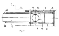
- Guide rod 8 is displaceable, the piston rod 10 of the hydraulic cylinder 9 (FIG. 4) being articulated on the inside of the guide slide 7 under a slide widening 33 for the slide adjustment.
Abstract
Description
Die Erfindung betrifft eine Einrichtung an einem Transportfahrzeug zum Aufbringen eines blasenden oder saugenden Luftstroms auf Verkehrsflächen, gemäß dem Oberbegriff von Anspruch 1. Gemäß einem weiteren Vorschlag betrifft die Erfindung eine an einem Transportfahrzeug heckseitig angeordnete Blaseinrichtung zur Beseitigung von Schneestaub oder Schneematsch auf Verkehrsflächen gemäß dem Oberbegriff von Anspruch 4.The invention relates to a device on a transport vehicle for applying a blowing or sucking air flow to traffic areas, according to the preamble of claim 1. According to a further proposal, the invention relates to a blowing device arranged on the rear of a transport vehicle for removing snow dust or slush on traffic areas according to the preamble of
Derartige Einrichtungen sind aus der EP-A-0 261 097 bekannt, eine Einrichtung gemäß dem Oberbegriff von Anspruch 1 zudem aus der US-A-4 633 603.Such devices are known from EP-A-0 261 097, a device according to the preamble of claim 1 also from US-A-4 633 603.
Bei derartigen Einrichtungen besteht das Bedürfnis, sie für die Transportfahrt in eine angehobene Position zu bringen, so daß eine ausreichende Bodenfreiheit gewährleistet ist. Gemäß der EP-A-0 261 097 ist daher die Blasdüse über einen anhebbaren Ausleger am Heck des Transportfahrzeuges befestigt, und der Luftkanal umfaßt zwei im Bereich der beiden Gelenke des Auslegers vorgesehene flexible Abschnitte. Gemäß der US-A-4 633 603 ist ein vertikales, unterteiltes, teleskopisch verlänger- und verkürzbares Blasrohr vorgesehen, welches das Anheben der Blasdüse mittels eines Hydraulikzylinders ermöglicht.With such devices, there is a need to bring them into a raised position for the transport journey, so that sufficient ground clearance is ensured. According to EP-A-0 261 097, the blowing nozzle is therefore fastened to the rear of the transport vehicle by means of a boom which can be raised, and the air duct comprises two flexible sections which are provided in the region of the two joints of the boom. According to US-A-4 633 603 is a vertical, divided, telescopically extendable and shortenable blow pipe provided that enables the blowing nozzle to be raised by means of a hydraulic cylinder.
Bei der in der EP-A-0 261 097 offenbarten Lösung ist von Nachteil, daß die Bodendüse weit nach hinten über das Fahrzeug hinausragt und somit insbesondere die Manövrierfähigkeit behindert. Zudem ruht, wie auch beim Lösungsvorschlag gemäß der US-A-4 633 603, das gesamte Gewicht der Blasdüse auf dem Hydraulikzylinder, wodurch dieser einer ständigen Belastung ausgesetzt ist.In the solution disclosed in EP-A-0 261 097, it is disadvantageous that the floor nozzle extends far beyond the vehicle and thus in particular impairs maneuverability. In addition, as with the proposed solution according to US-A-4 633 603, the entire weight of the blowing nozzle rests on the hydraulic cylinder, as a result of which the latter is subjected to a constant load.
Desweiteren ist es bei heckseitig angeordneten Einrichtungen der in Anspruch 1 genannten Art bekannt, die Bodendüse nach oben zu klappen; sie steht dann aber nach hinten über das Fahrzeugheck hinaus. Bei im Zwischenachsbereich angeordneten Blas- und Saugeinrichtungen der in Anspruch 1 genannten Art fehlt in der Regel der für das Hochklappen der Bodendüse erforderliche Freiraum unterhalb des Fahrzeugs; daher kommen dort bekanntermaßen entweder demontierbare oder an flexiblen Schläuchen angeordnete Bodendüsen in Frage, welche ein begrenztes vertikales Abheben von der Verkehrsfläche ermöglichen.Furthermore, it is known in rear-mounted devices of the type mentioned in claim 1 to fold the floor nozzle upwards; but then it stands behind the rear of the vehicle. In the case of blowing and suction devices arranged in the intermediate axle area of the type mentioned in claim 1, the space below the vehicle required for folding up the floor nozzle is generally missing; therefore, as is known, either removable or arranged on flexible hoses floor nozzles in question, which allow a limited vertical lifting from the traffic area.
Bei einer bekannten Blaseinrichtung der in Anspruch 4 genannten Art, welche ein Verschwenken der Bodendüse um 180° zwischen zwei bezüglich der Fahrzeuglängsachse gegenüberliegenden Blasstellungen ermöglicht, wird die Bodendüse für die Transportstellung in die Mitte geschwenkt und dann nach oben geklappt, so daß sie beträchtlich über das Fahrzeugheck hinausragt. Dadurch ergibt sich eine größere Gesamtlänge des Fahrzeugs, was beim Rangieren auf engem Raum hinderlich ist und außerdem eine Gefährdung anderer Verkehrsteilnehmer darstellt.In a known blowing device of the type mentioned in
Der vorliegenden Erfindung liegt die Aufgabe zugrunde, Einrichtungen der eingangs genannten Art derart auszubilden, daß sie in der Transportstellung, also ohne Beeinträchtigung der Bodenfreiheit des Fahrzeugs, nicht über den heckseitigen Fahrzeugumriß hinausragen. Dabei soll die Einrichtung kompakt und unanfällig gegen Störungen sein, wobei insbesondere die Belastung der hydraulischen Hubeinrichtung verringert werden soll.The present invention has for its object to design devices of the type mentioned in such a way that they do not protrude beyond the rear outline of the vehicle in the transport position, ie without impairing the ground clearance of the vehicle. The device should be compact and not susceptible to malfunctions, in particular the load on the hydraulic lifting device should be reduced.
Die Lösung dieser Aufgabe erfolgt durch die in den Ansprüchen 1 und 4 angegebenen Merkmale.This object is achieved by the features specified in
Ein allgemeiner Grundgedanke der Erfindung (Ansprüche 1 und 2) besteht also darin, für die Transportfahrt den Luftschacht zu trennen und seinen abgetrennten unteren Teil seitlich des oberen Teils und erhöht anzuordnen, so daß in der Transportstellung alle Teile der Einrichtung innerhalb des Fahrzeugumrisses angeordnet sind. Damit kann in der Transportstellung eine Bodenfreiheit von 250 mm und darüber sichergestellt werden.A general basic idea of the invention (claims 1 and 2) is therefore to separate the air duct for the transport journey and to arrange its separated lower part laterally of the upper part and elevated, so that in the transport position all parts of the device are arranged within the vehicle outline. This ensures a ground clearance of 250 mm and above in the transport position.
Wegen der im Bereich der Trennebene vorgesehenen Dichtungsmittel ist es zur Schonung derselben von besonderer Bedeutung, daß beim Trennen des Luftschachts in der Trennebene keine Scherkräfte auf die Dichtung ausgeübt werden.Because of the sealing means provided in the area of the parting plane, it is of particular importance to protect them that no shear forces are exerted on the seal when the air duct is separated in the parting plane.
Nach Anspruch 2 wird diese Forderung dadurch verwirklicht, daß der untere Schachtteil zusammen mit der Bodendüse längs der Führung zunächst nach unten bis zur Freigabe der Dichtung und anschließend seitwärts und nach oben in die obere Transportstellung bringbar ist.According to
Nach Anspruch 3 gelingt es, ein reibungsfreies Abheben der Dichtung dadurch sicherzustellen, daß der untere Schachtteil zusammen mit der Bodendüse längs einer Schrägführung in die obere Transportstellung verschiebbar ist und daß die Neigung der Schrägführung gegenüber der Horizontalebene geringer ist als jene der Trennebene.According to
Als einfachste und daher besonders vorteilhafte Ausführung eignet sich gemäß Anspruch 4 eine schiefe Trennebene, welche mit der Ebene einer nach seitwärts und oben gerichteten Schrägführung einen spitzen Winkel einschließt, derart, daß der untere Schachtteil zusammen mit der Bodendüse längs einer translatorischen Schrägführung auf eine Seite des Fahrzeugs in die obere Transportstellung verschiebbar ist, wobei die Ebene der Schrägführung mit der Horizontalebene einen spitzeren Winkel einschließt als die Trennebene. Diese Geometrie sichert einerseits ein reibungsfreies Abheben der Dichtungsmittel im Bereich der Trennebene und andererseits ein Abheben der Bodendüse von der Verkehrswegoberfläche, ohne daß die Bodendüse in der Verschieberichtung darauf gleitet.The simplest and therefore particularly advantageous embodiment is, according to
Dabei beträgt der Winkel zwischen Trennebene und Horizontalebene 15° bis 30°, vorzugsweise 20° bis 25° und es läßt sich eine ausreichend hohe Transportstellung des unteren Schachtteils und damit der Bodendüse erzielen, wenn die Ebene der Schrägführung und die Trennebene einen Winkel zwischen 2 und 6 Winkelgraden miteinander einschliessen; bereits dieser relativ kleine Winkel sichert ein reibungsfreies Abheben der Dichtungsmittel in der Trennebene einerseits und ein ausreichend steiles Abheben der Bodendüse vom Boden andererseits.The angle between the parting plane and the horizontal plane is 15 ° to 30 °, preferably 20 ° to 25 ° and it is possible to achieve a sufficiently high transport position of the lower shaft part and thus the floor nozzle if the plane of the inclined guide and the parting plane make an angle between 2 and Include 6 degrees of angle with each other; even this relatively small angle ensures that the sealant is lifted off smoothly in the parting plane on the one hand and that the floor nozzle is lifted off the floor in a sufficiently steep manner on the other hand.
Nach einer besonders einfachen Ausführungsform ist vorgesehen, daß die Schrägführung als auf Führungsstangen verfahrbarer Schlitten ausgebildet ist, an welchem der untere Schachtteil mit der Bodendüse aufgehängt ist. Bevorzugt ist dieser Schlitten mittels eines Hydraulikzylinders verfahrbar, welcher vor äußerer Einwirkung geschützt auf der der Fahrzeugachse zugewandten Innenseite des Schlittens angelenkt und dort parallel zu den Führungsstangen ausfahrbar ist.According to a particularly simple embodiment, it is provided that the inclined guide is designed as a carriage which can be moved on guide rods, on which the lower shaft part is suspended with the floor nozzle. This carriage can preferably be moved by means of a hydraulic cylinder, which is articulated from the outside on the inside of the carriage facing the vehicle axis and can be extended there parallel to the guide rods.
Zweckmäßigerweise weist der untere Schachtteil einen horizontal verlaufenden Abschnitt auf, der in der Arbeitsstellung mit seinem äußeren, ausgeschwenkten Ende über die Seitenkontur des Fahrzeugs hinausragt, je nachdem, auf welche Seite des Fahrzeugs der untere Schachtteil um den genannten Drehkranz verschwenkt ist. Der Luftstrom wird dabei von außerhalb der zugeordneten Fahrzeugräder quer zum Fahrzeug durch die Bodendüse hindurch auf die gegenüberliegende Seite geblasen, wobei er die auf der Verkehrswegoberfläche vorhandene Schneeauflage erfaßt, so daß der Schnee auf der gegenüberliegenden Fahrzeugseite außerhalb der Fahrzeugspur in mehr oder weniger großer Entfernung, z.B. bis zu 5 m abgelagert wird.The lower manhole part expediently has a horizontally running section which, in the working position, projects with its outer, swung-out end beyond the side contour of the vehicle, depending on which side of the vehicle the lower manhole part is pivoted about the said turntable. The air flow is blown from outside the assigned vehicle wheels across the vehicle through the floor nozzle to the opposite side, whereby it detects the snow layer on the surface of the traffic route, so that the snow on the opposite side of the vehicle outside the vehicle lane at a greater or lesser distance, e.g. is deposited up to 5 m.
Nach einer vorteilhaften Ausführungsform des unteren Schachtteils ist vorgesehen, daß dessen horizontaler Abschnitt mit seinem äußeren Ende über ein Bogenstück mit der Bodendüse verbunden ist und in der Arbeitsstellung mit seinem inneren Ende über ein vertikales, an die Trennebene angrenzendes Anschlußstück etwa in der Mittellängsebene des Fahrzeugs an dem oberen Schachtteil angeschlossen ist. Das Bogenstück ragt in der Arbeitsstellung über die seitliche Umrißlinie des Fahrzeughecks hinaus.According to an advantageous embodiment of the lower part of the shaft, it is provided that its horizontal section with its outer end via an arc piece is connected to the floor nozzle and is connected in the working position with its inner end via a vertical connecting piece adjacent to the parting plane approximately in the central longitudinal plane of the vehicle to the upper shaft part. In the working position, the bow piece protrudes beyond the side outline of the rear of the vehicle.
Die Bodendüse selbst ist zweckmäßig als zur Verkehrsfläche hin offener Kanal ausgebildet; sie erstreckt sich etwa parallel zum horizontalen Abschnitt des unteren Schachtteils zur Fahrzeugmitte hin und über diese hinaus, so daß ihre Ausblasöffnung auf einer Seitenerstreckung von etwa drei Vierteln der Fahrzeugbreite endet. Dementsprechend ragt das andere Ende der Bodendüse mit dem daran angeschlossenen Bogenstück des unteren Schachtteils etwa zu einem Viertel der Fahrzeugbreite über diese hinaus, so daß in der Transportstellung die gesamte Blaseinrichtung vollständig innerhalb der heckseitigen Fahrzeugkontur untergebracht ist.The floor nozzle itself is expediently designed as a channel open to the traffic area; it extends approximately parallel to the horizontal section of the lower shaft part towards the center of the vehicle and beyond, so that its outlet opening ends on a side extension of approximately three quarters of the vehicle width. Accordingly, the other end of the floor nozzle with the arc piece of the lower shaft part connected to it protrudes about a quarter of the vehicle width beyond it, so that in the transport position the entire blowing device is completely accommodated within the rear vehicle contour.
Um eine möglichst hohe Anordnung der Trennebene zu erzielen, wodurch sich gleichzeitig deren Neigung gegenüber der Horizontalebene reduziert, ist es zweckmäßig, daß der Drehkranz im Bereich des vertikalen Anschlußstücks des unteren Schachtteils angeordnet ist.In order to achieve the highest possible arrangement of the parting plane, which at the same time reduces its inclination with respect to the horizontal plane, it is expedient for the slewing ring to be arranged in the region of the vertical connecting piece of the lower shaft part.
Auch in Längsrichtung des Fahrzeugs tritt die Blaseinrichtung hinter die rückwärtige Begrenzung des Fahrzeugaufbaus zurück; die Blaseinrichtung sitzt bevorzugt unterhalb des Ventilators, der von einem auf dem hinter dem Fahrerhaus befindlichen Teil des Chassis angeordneten Aufbaumotor angetrieben wird.Also in the longitudinal direction of the vehicle, the blower device falls behind the rear boundary of the vehicle body; the blowing device is preferably located below the fan, which is driven by a built-on motor arranged on the part of the chassis located behind the driver's cab.
Die erfindungsgemäße Blaseinrichtung findet bevorzugt Anwendung im Winterdienst an einem LKW als Trägerfahrzeug, wobei frontseitig am LKW ein Schneepflug angebaut ist und zwischen den Achsen des Fahrzeugs eine Schneekehrwalze vorgesehen ist. Ein derart ausgerüstetes Trägerfahrzeug eignet sich für den Winterdienst auf Straßen, Autobahnen und insbesondere für den großflächigen Einsatz auf Flughäfen. Die kompakte Ausführung und achsnahe Anordnung der Blaseinrichtung verleihen dem Trägerfahrzeug eine besonders gute Wendigkeit.The blowing device according to the invention is preferably used in winter service on a truck as the carrier vehicle, a snow plow being attached to the front of the truck and a snow brush roller being provided between the axles of the vehicle. A carrier vehicle equipped in this way is suitable for winter service on roads, highways and in particular for large-scale use at airports. The compact design and arrangement of the blowing device close to the axis give the carrier vehicle particularly good maneuverability.
Im folgenden wird ein Ausführungsbeispiel der Erfindung anhand der Zeichnung dargestellt. Es zeigt:
- Figur 1 eine heckseitige Ansicht des Trägerfahrzeugs mit Blaseinrichtung in der Arbeitsstellung,
Figur 2 eine Ansicht gemäß Fig. 1 mit Blaseinrichtung in der Transportstellung,Figur 3 einen Schnitt gemäß III - III der Fig. 1 durch die Blaseinrichtung undFigur 4 einen horizontalen Schnitt gemäß IV - IV der Fig. 1 durch die Blaseinrichtung.
- FIG. 1 shows a rear view of the carrier vehicle with a blowing device in the working position,
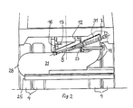
- FIG. 2 shows a view according to FIG. 1 with a blowing device in the transport position,
- 3 shows a section according to III - III of FIG. 1 through the blowing device and
- 4 shows a horizontal section according to IV - IV of FIG. 1 through the blowing device.
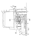
Figur 1 zeigt die heckseitige Ansicht eines Transportfahrzeugs 1, von welchem man die Konturen des Führerhauses 2 sowie eine Motor- und Gebläseverkleidung 3 als Aufbauten auf dem Chassis erkennt. Hinter der Hinterachse ist mittig an der Unterseite eines nach hinten überstehenden Teils eines Aufbaurahmens 5 (Figur 3) des Chassis eine Blaseinrichtung 6 aufgehängt; letztere ist abgestützt auf einem Schlitten 7, der auf Führungsstangen 8 mittels eines hydraulischen Verstellzylinders 9 (Figur 4) an einer Kolbenstange 10, welche parallel zu den Führungsstangen 8 verläuft, verschiebbar ist. Durch den Schlitten 7 hindurch erstreckt sich in vertikaler Richtung ein Luftschacht 11, welcher mit seinem oberen Ende über eine Gummimanschette 12 am Auslaßtrichter 13 (Figur 3) eines auf dem Aufbraurahmen 5 aufgesetzten Ventilators 14 (Figur 3) angeschlossen ist. Die Ventilatorwelle 15 (Figur 3) wird über einen nicht dargestellten Aufbaumotor angetrieben.Figure 1 shows the rear view of a transport vehicle 1, from which you can see the contours of the
Der Luftschacht 11 ist längs einer schrägen Trennebene T geteilt, wobei ein oberer Schachtteil 16 mit der Gummimanschette 12 verbunden und mittels eines Stützprofils 17 an einem rahmenfesten Steg 18 befestigt ist. Ein unterer Schachtteil 19 ist am Schlitten 7 befestigt und umfaßt unterhalb des Schlittens 7 einen Drehkranz 20, welcher eine Verdrehung eines horizontalen Abschnitts 21 des unteren Schachtteils 19 um 180°, d.h. aus einer Arbeitsstellung wie in Fig. 1 dargestellt in eine entgegengesetzte Arbeitsstellung ermöglicht. Gemäß Fig. 3 besitzt der Drehkranz 20 eine Verzahnung 22, welche mit einem Schneckenantrieb 23, der mittels eines (nicht dargestellten) Hydromotors betätigbar ist, zusammenwirkt.The
Der horizontale Abschnitt 21 des unteren Schachtteils 19 besitzt in seinem Inneren ein Leitblech 24 zur Umlenkung des Blasluftstroms in eine Bodendüse 25, welche die Form eines länglichen Kanalstücks aufweist und durch welche die Blasluft in Richtung des Pfeiles B hindurchströmt und den auf der Verkehrswegoberfläche 26 erfaßten Schnee gemäß der in Fig. 1 dargestellten Arbeitsstellung nach rechts bläst und auf der rechten Fahrzeugseite ablegt. Der horizontale Abschnitt 21 des unteren Schachtteils 19 ist an der Unterseite des Drehkranzes 20 an diesen mittels eines vertikalen Anschlußstücks 27 angeschlossen; an seinem anderen Ende ist der horizontale Abschnitt 21 über ein sich nach unten hin erweiterndes Bogenstücks 28 mit der Bodendüse verbunden. Gemäß Fig. 3 ist die Bodendüse 25 über einen Zwischenrahmen 29 an der Unterseite des horizontalen Abschnitts 21 des unteren Schachtteils 19 angeschlossen; mit seitlichen Gummileisten 30 ist sie gegenüber der Verkehrswegoberfläche 26 abgedichtet.The
In der Trennebene T des Luftschachts 11 sind der obere Schachtteil 16 und der untere Schachtteil 19 mittels einer umlaufenden Dichtung nach außen abgedichtet, so daß die vom Ventilator erzeugte Blasluft in der Arbeitsstellung der Blaseinrichtung 6 ungehindert im Inneren des Luftschachts 11 nach unten in Richtung Bodendüse 25 strömt. Die Dichtung umfaßt Dichtmittel 31, z.B. in Form elastomerer Dichtstreifen, welche umlaufend in entsprechenden, an die Trennebene T angrenzenden Falzen im oberen Schachtteil 16 bzw. unteren Schachtteil 19 aufgenommen sind. Damit die Dichtungsmittel 31 beim Verbringen des unteren Schachtteils 19 aus der Arbeitsstellung in die in Fig. 2 dargestellte Transportstellung nicht verschleißen, ist vorgesehen, daß die durch die Führungsstangen 8 vorgegebene Ebene S der Schrägführung mit der Trennebene einen spitzen Winkel α bildet, der etwa 2° bis 6°, bevorzugt 4° beträgt. Dadurch ist sichergestellt, daß bei einem Verfahren des unteren Schachtteils 19 am Schlitten 7 längs den Führungsstangen 8 in die obere Anschlagposition, in welcher die Transportstellung erreicht ist, der Dichtungskontakt reibungsfrei unterbrochen wird, d.h. die Unterbrechung erfolgt bereits während eines äußerst kurzen anfänglichen Verschiebewegs. Während dieses Verschiebewegs erfolgt gleichzeitig ein deutliches vertikales Abheben der Gummileisten 30 der Bodendüse 25, d.h. auch auf seiten der Bodenleisten 30 kommt es beim Verschieben des unteren Schachtteils 19 aus der Arbeitsstellung in die Transportstellung zu keinen Abriebserscheinungen, da ein evtl. vorhandene Kontakt mit der Verkehrswegoberfläche 26 bereits zu Beginn der Verschiebebewegung aufgehoben wird.In the parting plane T of the
Der Winkel zwischen der Trennebene T und der Horizontalebene ergibt sich im wesentlichen aufgrund der Abmessungen des Fahrzeugs und der gewünschten Bodenfreiheit. Dabei genügt ein Winkel zwischen 15° und 30°, bevorzugt zwischen 20° und 25°; für die Neigung der Ebene der Schrägführung gegenüber der Horizontalen ergibt sich dabei ein Winkel etwa um 20°, womit bei dem dargestellten Ausführungsbeispiel eine Bodenfreiheit f (Fig. 2) von ca. 250 mm erzielbar ist.The angle between the parting plane T and the horizontal plane essentially results from the dimensions of the vehicle and the desired ground clearance. An angle between 15 ° and 30 °, preferably between 20 ° and 25 °, is sufficient; for the inclination of the plane of the inclined guide An angle of approximately 20 ° results with respect to the horizontal, with which a ground clearance f (FIG. 2) of approximately 250 mm can be achieved in the exemplary embodiment shown.
In Figur 2 ist die Blaseinrichtung in der Transportstellung dargestellt. Der Schlitten 7 ist dabei längs der Führungsstange 8 nach rechts oben in eine Anschlagstellung verschoben. Man erkennt auf seiten des unteren Schachtteils 19 die über die Verbindungsebene vorspringenden Dichtungsmittel 31. In der gezeichneten Transportstellung findet die gesamte Blaseinrichtung zwischen den seitlichen Außenkonturen des Fahrzeugshecks Platz, d.h. überstehende Teile, die im Verkehr hinderlich sein könnten, sind nicht vorhanden. Es versteht sich von selbst, daß für das Verschieben des unteren Schachtteils 19 in die in Fig. 2 dargestellte Transportstellung die Blaseinrichtung sich in der um den Drehkranz 20 nach links verschwenkten Lage befindet.In Figure 2, the blowing device is shown in the transport position. The
In der Schnittdarstellung gemäß Fig. 3 erkennt man deutlich, daß die Blaseinrichtung 6 unterhalb eines über das Fahrzeugheck 32 nach hinten vorstehenden Aufbaurahmens 5 untergebracht ist. Der Führungsschlitten 7 ist längs der3 clearly shows that the
Führungsstange 8 verschiebbar, wobei auf der Innenseite des Führungsschlittens 7 unter einer Schlittenverbreiterung 33 die Kolbenstange 10 des Hydraulikzylinders 9 (Fig. 4) für die Schlittenverstellung angelenkt ist.
In der Schnittdarstellung gemäß Fig. 4 ist die Bodendüse 25, in Übereinstimmung mit Fig. 1, in der nach links ausgeschwenkten Stellung gezeichnet. Oer Schlitten 7, welcher den Luftschacht 11 umfaßt, ist auf zwei gegenüberliegenden, zueinander parallelen Führungsstangen 8 geführt, welche gemeinsam die Ebene der Schrägführung S beschreiben. Mit strichpunktierten Linien ist eine Draufsicht auf das Fahrzeugheck angegeben, welche erkennen läßt, daß in der Arbeitsstellung die Bodendüse 25 und das Bogenstück 28 des horizontalen Abschnitts 21 des unteren Schachtteils 19 über die linke Seitenkontur L des Fahrzeugs hinausragen.4, the
Claims (12)
- Unit on a transport vehicle for directing a current of air onto road surfaces by blowing or suction, having a base nozzle (25) which, when in operating position, is connected by way of an air shaft (11) to a fan (14) attached to the vehicle (1) and can be moved into an upper transport position, wherein a dividing plane (T) is provided which separates the air shaft (11) into an upper (16) and a lower shaft section (19) and in which sealing means (31) are arranged to seal the shaft sections (16, 19) together in operating position, characterised in that said lower shaft section (19) together with said base nozzle (25) may be moved sideways along a guideway next to said air shaft (11) and upwards into the upper transport position.
- Unit according to Claim 1, characterised in that said lower shaft section (19) together with said base nozzle (25) may be moved along a guideway first downwards until the seal is released and then sideways and upwards into the upper transport position.
- Unit according to Claim 1, characterised in that an inclined dividing plane (T) separating said air shaft (11) is provided, in which sealing means (31) are arranged which seal said upper shaft section (16) and said lower shaft section (19) together in operating position, that said lower shaft section (19) may be shifted together with said base nozzle (25) along an inclined guideway into the upper transport position and that the gradient of said inclined guideway in relation to the horizontal plane is less than that of the dividing plane (T).
- Blower unit on a transport vehicle for the removal of fine dry or wet snow on road surfaces arranged at the rear of the vehicle (1) and having a base nozzle (25) which, when in operating position, is connected by way of an air shaft (11) to a fan (14) attached to the vehicle (1), wherein the air shaft (11) is separated into an upper (16) and a lower shaft section (19) by a dividing plane (T), in which sealing means (31) are arranged to seal the shaft sections (16, 19) together in operating position, and wherein a turning ring (20) with a vertical rotational axis is installed in the air shaft (11) and the base nozzle (25) may be moved into an upper transport position, characterised in that said turning ring (20) permits said base nozzle (25) to swivel around 180° between two blower positions lying opposite one another in relation to the longitudinal axis of the vehicle, that said lower shaft section (19) may be shifted together with said base nozzle (25) along a translatory inclined guideway on one side of the vehicle (1) into the upper transport position and that the dividing plane (T) runs on an incline and the plane (S) of the inclined guideway is at a more acute angle from the horizontal plane than said dividing plane (T).
- Blower unit according to Claim 4, characterised in that the angle between the dividing plane (T) and the horizontal plane amounts to 15° to 30°, preferably 20° to 25°.
- Blower unit according to Claim 4, characterised in that the plane (S) of the inclined guideway and the dividing plane (T) lie at an angle (α) to one another of between 2 and 6 degrees.
- Blower unit according to Claim 4, characterised in that said inclined guideway comprises a cradle (7) which may be run on guide rods (8) and from which said lower shaft section (19) with said base nozzle (25) are suspended.
- Blower unit according to Claim 7, characterised in that said cradle (7) may be run by means of a hydraulic cylinder (9) which is coupled to said cradle (7) on its inside facing the vehicle axle and the piston (10) of which may be extended parallel to said guide rods (8).
- Blower unit according to Claim 4, characterised in that said lower shaft section (19) has a horizontal portion (21) which in operating position projects beyond the side contour of the vehicle (1) with its outer end when this is swivelled outwards.
- Blower unit according to Claim 9, characterised in that said horizontal portion (21) of said lower shaft section (19) is connected with its outer end to the base nozzle (25) by way of a bow-shaped connection (28) and in operating position is attached at its inner end to said upper shaft section (16) by way of a vertical joining piece (27) adjacent to said dividing plane (T), in approximately the central longitudinal plane of the vehicle (1).
- Blower unit according to Claim 9 or 10, characterised in that said base nozzle (25) is in the form of an open channel directed towards the road surface extending approximately parallel to the horizontal portion (21) of said lower shaft section (19) and towards the centre of the vehicle and beyond.
- Blower unit according to Claim 10, characterised in that said turning ring (20) is arranged in the area of the vertical joining piece (27) of said lower shaft section (19).
Priority Applications (1)
| Application Number | Priority Date | Filing Date | Title |
|---|---|---|---|
| AT90905486T ATE86326T1 (en) | 1989-04-04 | 1990-04-04 | DEVICE ON A TRANSPORT VEHICLE FOR APPLYING AN AIR FLOW TO TRAFFIC AREAS. |
Applications Claiming Priority (2)
| Application Number | Priority Date | Filing Date | Title |
|---|---|---|---|
| DE3910834A DE3910834C1 (en) | 1989-04-04 | 1989-04-04 | |
| DE3910834 | 1989-04-04 |
Publications (2)
| Publication Number | Publication Date |
|---|---|
| EP0417249A1 EP0417249A1 (en) | 1991-03-20 |
| EP0417249B1 true EP0417249B1 (en) | 1993-03-03 |
Family
ID=6377806
Family Applications (1)
| Application Number | Title | Priority Date | Filing Date |
|---|---|---|---|
| EP90905486A Expired - Lifetime EP0417249B1 (en) | 1989-04-04 | 1990-04-04 | Vehicle-mounted device for applying an air blast to road surfaces |
Country Status (3)
| Country | Link |
|---|---|
| EP (1) | EP0417249B1 (en) |
| DE (2) | DE3910834C1 (en) |
| WO (1) | WO1990012153A1 (en) |
Families Citing this family (2)
| Publication number | Priority date | Publication date | Assignee | Title |
|---|---|---|---|---|
| DE102004022120B4 (en) * | 2004-05-05 | 2007-11-15 | Karl Wiedemann | Device for cleaning communal facilities in the street area |
| DE102014017539B4 (en) | 2014-11-21 | 2019-01-17 | Hartmut Sassowsky | Joint renovation machine and method for its operation and its use |
Family Cites Families (12)
| Publication number | Priority date | Publication date | Assignee | Title |
|---|---|---|---|---|
| DE7223682U (en) * | 1972-11-09 | Streicher M Fa | Street sweeper | |
| CH441414A (en) * | 1964-08-28 | 1967-08-15 | Otto Prof Zweifel | Device for snow removal |
| US3515168A (en) * | 1968-05-31 | 1970-06-02 | Wayne Manufacturing Co | Street cleaner suction seal |
| CS149353B1 (en) * | 1970-08-12 | 1973-07-05 | ||
| DE2455199C3 (en) * | 1974-11-21 | 1982-10-07 | KIBO Kommunalmaschinen GmbH & Co KG, 8011 Hohenbrunn | Street cleaning machine |
| US4006511A (en) * | 1976-01-08 | 1977-02-08 | Fmc Corporation | Sweeper with recirculation hood and independent filter system |
| US4633603A (en) * | 1981-12-08 | 1987-01-06 | Pierre David | Snow removal apparatus |
| ATE56232T1 (en) * | 1986-09-16 | 1990-09-15 | Kahlbacher Anton | DEVICE FOR CLEARING SNOW, SNOW, WATER, DIRT OR THE LIKE FROM TRAFFIC AREAS. |
| DE8701741U1 (en) * | 1987-02-05 | 1987-04-02 | Kuepper, Willy, 7715 Braeunlingen, De | |
| US4773121A (en) * | 1987-02-27 | 1988-09-27 | Tymco, Inc. | High speed pick-up head |
| CN1012831B (en) * | 1987-04-23 | 1991-06-12 | 雷伯里地区企业沙恩公司 | Cleaning vehicle for cleaning ground surfaces provided with rigid surface |
| DE8806854U1 (en) * | 1988-05-26 | 1988-07-07 | Augl Ernst Gmbh & Co Kg | Additional equipment set for tractors used as a suction sweeper |
-
1989
- 1989-04-04 DE DE3910834A patent/DE3910834C1/de not_active Expired - Fee Related
-
1990
- 1990-04-04 WO PCT/EP1990/000528 patent/WO1990012153A1/en active IP Right Grant
- 1990-04-04 EP EP90905486A patent/EP0417249B1/en not_active Expired - Lifetime
- 1990-04-04 DE DE9090905486T patent/DE59000964D1/en not_active Expired - Fee Related
Also Published As
| Publication number | Publication date |
|---|---|
| EP0417249A1 (en) | 1991-03-20 |
| DE3910834C1 (en) | 1991-01-17 |
| DE59000964D1 (en) | 1993-04-08 |
| WO1990012153A1 (en) | 1990-10-18 |
Similar Documents
| Publication | Publication Date | Title |
|---|---|---|
| EP0261097B1 (en) | Apparatus for removing snow, snow-mud, water, dirt or the like from traffic areas | |
| DE2751423A1 (en) | VEHICLE RECEIVING VACUUM | |
| EP0613980B1 (en) | Ballast levelling machine | |
| DE202011001292U1 (en) | Tunnel washing vehicle | |
| DE3437990A1 (en) | SUCTION CHAMBER ON A SWEEPER | |
| DE202012008313U1 (en) | Tram tracks cleaning machine | |
| EP0482293B1 (en) | Groundworking machine and undercarriage | |
| DE3604053C2 (en) | ||
| DE4108673A1 (en) | Process for continuous cleaning of railway ballast - involves using hood equipped with compressed air and high pressure water jets, attached to constantly moving vehicle | |
| DE2217975A1 (en) | ON A VEHICLE, IN PARTICULAR RAILWAY VEHICLE, EQUIPMENT ARRANGED FOR CLEANING GRAPH BEDS, SLEEPERS AND SIMILAR RAILWAYS | |
| EP0603149A1 (en) | Vacuum machine | |
| EP0417249B1 (en) | Vehicle-mounted device for applying an air blast to road surfaces | |
| EP0447601A1 (en) | Apparatus for cleaning road markings | |
| EP2578751A1 (en) | Sweeping broom apparatus with air blast system | |
| DE3333476C2 (en) | ||
| DE2947396A1 (en) | STEM SNOW DEVICE FOR A RAIL VEHICLE | |
| AT389339B (en) | Mobile device for road cleaning | |
| EP0435978B1 (en) | Road-sweeping lorry | |
| EP0197259A2 (en) | Road sweeper with double cylindrical brushes | |
| WO2016198456A1 (en) | Air conduction element for reducing air resistance of a load-carrying vehicle | |
| DE2916012A1 (en) | Servo suction road cleaning machine - has air duct with end suction and blower nozzles cleaning under parked vehicles | |
| DE2541108A1 (en) | Articulated road sweeping machine with knee joint steering - pneumatic suction rubbish collector mechanism | |
| EP1612335A2 (en) | Automotive sweeping apparatus | |
| DE2235131A1 (en) | VEHICLE FOR CLEANING STREET PAVERS AND THE LIKE | |
| DE4416132C2 (en) | Suction device for sweepers |
Legal Events
| Date | Code | Title | Description |
|---|---|---|---|
| PUAI | Public reference made under article 153(3) epc to a published international application that has entered the european phase |
Free format text: ORIGINAL CODE: 0009012 |
|
| AK | Designated contracting states |
Kind code of ref document: A1 Designated state(s): AT CH DE LI SE |
|
| 17P | Request for examination filed |
Effective date: 19910220 |
|
| 17Q | First examination report despatched |
Effective date: 19911008 |
|
| GRAA | (expected) grant |
Free format text: ORIGINAL CODE: 0009210 |
|
| AK | Designated contracting states |
Kind code of ref document: B1 Designated state(s): AT CH DE LI SE |
|
| PG25 | Lapsed in a contracting state [announced via postgrant information from national office to epo] |
Ref country code: SE Effective date: 19930303 |
|
| REF | Corresponds to: |
Ref document number: 86326 Country of ref document: AT Date of ref document: 19930315 Kind code of ref document: T |
|
| REF | Corresponds to: |
Ref document number: 59000964 Country of ref document: DE Date of ref document: 19930408 |
|
| PLBE | No opposition filed within time limit |
Free format text: ORIGINAL CODE: 0009261 |
|
| STAA | Information on the status of an ep patent application or granted ep patent |
Free format text: STATUS: NO OPPOSITION FILED WITHIN TIME LIMIT |
|
| 26N | No opposition filed | ||
| PGFP | Annual fee paid to national office [announced via postgrant information from national office to epo] |
Ref country code: AT Payment date: 19980423 Year of fee payment: 9 |
|
| PGFP | Annual fee paid to national office [announced via postgrant information from national office to epo] |
Ref country code: CH Payment date: 19980424 Year of fee payment: 9 |
|
| PG25 | Lapsed in a contracting state [announced via postgrant information from national office to epo] |
Ref country code: AT Free format text: LAPSE BECAUSE OF NON-PAYMENT OF DUE FEES Effective date: 19990404 |
|
| PG25 | Lapsed in a contracting state [announced via postgrant information from national office to epo] |
Ref country code: LI Free format text: LAPSE BECAUSE OF NON-PAYMENT OF DUE FEES Effective date: 19990430 Ref country code: CH Free format text: LAPSE BECAUSE OF NON-PAYMENT OF DUE FEES Effective date: 19990430 |
|
| REG | Reference to a national code |
Ref country code: CH Ref legal event code: PL |
|
| PGFP | Annual fee paid to national office [announced via postgrant information from national office to epo] |
Ref country code: DE Payment date: 20000627 Year of fee payment: 11 |
|
| PG25 | Lapsed in a contracting state [announced via postgrant information from national office to epo] |
Ref country code: DE Free format text: LAPSE BECAUSE OF NON-PAYMENT OF DUE FEES Effective date: 20020201 |