EP0415520B1 - Easy-open package and method of forming the same - Google Patents
Easy-open package and method of forming the same Download PDFInfo
- Publication number
- EP0415520B1 EP0415520B1 EP90306786A EP90306786A EP0415520B1 EP 0415520 B1 EP0415520 B1 EP 0415520B1 EP 90306786 A EP90306786 A EP 90306786A EP 90306786 A EP90306786 A EP 90306786A EP 0415520 B1 EP0415520 B1 EP 0415520B1
- Authority
- EP
- European Patent Office
- Prior art keywords
- film
- support
- films
- product
- bond
- Prior art date
- Legal status (The legal status is an assumption and is not a legal conclusion. Google has not performed a legal analysis and makes no representation as to the accuracy of the status listed.)
- Expired - Lifetime
Links
- 238000000034 method Methods 0.000 title claims description 7
- 230000032798 delamination Effects 0.000 claims abstract description 16
- 238000010438 heat treatment Methods 0.000 claims description 5
- 235000012054 meals Nutrition 0.000 claims description 4
- 238000011065 in-situ storage Methods 0.000 claims 1
- 230000000977 initiatory effect Effects 0.000 claims 1
- 238000003860 storage Methods 0.000 claims 1
- 230000035515 penetration Effects 0.000 abstract 1
- 239000010408 film Substances 0.000 description 86
- 239000010410 layer Substances 0.000 description 48
- 238000007789 sealing Methods 0.000 description 13
- 230000004888 barrier function Effects 0.000 description 5
- 229920001903 high density polyethylene Polymers 0.000 description 3
- 239000004700 high-density polyethylene Substances 0.000 description 3
- 229920001684 low density polyethylene Polymers 0.000 description 3
- 239000004702 low-density polyethylene Substances 0.000 description 3
- 238000004806 packaging method and process Methods 0.000 description 3
- 239000004677 Nylon Substances 0.000 description 2
- 238000010276 construction Methods 0.000 description 2
- 230000000694 effects Effects 0.000 description 2
- 239000005038 ethylene vinyl acetate Substances 0.000 description 2
- 239000007789 gas Substances 0.000 description 2
- 239000000463 material Substances 0.000 description 2
- 229920001778 nylon Polymers 0.000 description 2
- 229920006280 packaging film Polymers 0.000 description 2
- 239000012785 packaging film Substances 0.000 description 2
- 239000000565 sealant Substances 0.000 description 2
- 239000004793 Polystyrene Substances 0.000 description 1
- 239000000853 adhesive Substances 0.000 description 1
- 230000001070 adhesive effect Effects 0.000 description 1
- QVGXLLKOCUKJST-UHFFFAOYSA-N atomic oxygen Chemical compound [O] QVGXLLKOCUKJST-UHFFFAOYSA-N 0.000 description 1
- DQXBYHZEEUGOBF-UHFFFAOYSA-N but-3-enoic acid;ethene Chemical compound C=C.OC(=O)CC=C DQXBYHZEEUGOBF-UHFFFAOYSA-N 0.000 description 1
- 239000013039 cover film Substances 0.000 description 1
- 239000004715 ethylene vinyl alcohol Substances 0.000 description 1
- 238000007654 immersion Methods 0.000 description 1
- 239000011229 interlayer Substances 0.000 description 1
- 229920000554 ionomer Polymers 0.000 description 1
- 239000001301 oxygen Substances 0.000 description 1
- 229910052760 oxygen Inorganic materials 0.000 description 1
- 229920001200 poly(ethylene-vinyl acetate) Polymers 0.000 description 1
- 229920000728 polyester Polymers 0.000 description 1
- 229920002223 polystyrene Polymers 0.000 description 1
- 239000005033 polyvinylidene chloride Substances 0.000 description 1
- 238000003856 thermoforming Methods 0.000 description 1
- 238000009966 trimming Methods 0.000 description 1
- XLYOFNOQVPJJNP-UHFFFAOYSA-N water Substances O XLYOFNOQVPJJNP-UHFFFAOYSA-N 0.000 description 1
- 230000003313 weakening effect Effects 0.000 description 1
Images
Classifications
-
- B—PERFORMING OPERATIONS; TRANSPORTING
- B32—LAYERED PRODUCTS
- B32B—LAYERED PRODUCTS, i.e. PRODUCTS BUILT-UP OF STRATA OF FLAT OR NON-FLAT, e.g. CELLULAR OR HONEYCOMB, FORM
- B32B7/00—Layered products characterised by the relation between layers; Layered products characterised by the relative orientation of features between layers, or by the relative values of a measurable parameter between layers, i.e. products comprising layers having different physical, chemical or physicochemical properties; Layered products characterised by the interconnection of layers
- B32B7/04—Interconnection of layers
- B32B7/06—Interconnection of layers permitting easy separation
-
- B—PERFORMING OPERATIONS; TRANSPORTING
- B32—LAYERED PRODUCTS
- B32B—LAYERED PRODUCTS, i.e. PRODUCTS BUILT-UP OF STRATA OF FLAT OR NON-FLAT, e.g. CELLULAR OR HONEYCOMB, FORM
- B32B3/00—Layered products comprising a layer with external or internal discontinuities or unevennesses, or a layer of non-planar shape; Layered products comprising a layer having particular features of form
- B32B3/02—Layered products comprising a layer with external or internal discontinuities or unevennesses, or a layer of non-planar shape; Layered products comprising a layer having particular features of form characterised by features of form at particular places, e.g. in edge regions
- B32B3/04—Layered products comprising a layer with external or internal discontinuities or unevennesses, or a layer of non-planar shape; Layered products comprising a layer having particular features of form characterised by features of form at particular places, e.g. in edge regions characterised by at least one layer folded at the edge, e.g. over another layer ; characterised by at least one layer enveloping or enclosing a material
-
- B—PERFORMING OPERATIONS; TRANSPORTING
- B65—CONVEYING; PACKING; STORING; HANDLING THIN OR FILAMENTARY MATERIAL
- B65B—MACHINES, APPARATUS OR DEVICES FOR, OR METHODS OF, PACKAGING ARTICLES OR MATERIALS; UNPACKING
- B65B61/00—Auxiliary devices, not otherwise provided for, for operating on sheets, blanks, webs, binding material, containers or packages
- B65B61/02—Auxiliary devices, not otherwise provided for, for operating on sheets, blanks, webs, binding material, containers or packages for perforating, scoring, slitting, or applying code or date marks on material prior to packaging
-
- B—PERFORMING OPERATIONS; TRANSPORTING
- B65—CONVEYING; PACKING; STORING; HANDLING THIN OR FILAMENTARY MATERIAL
- B65D—CONTAINERS FOR STORAGE OR TRANSPORT OF ARTICLES OR MATERIALS, e.g. BAGS, BARRELS, BOTTLES, BOXES, CANS, CARTONS, CRATES, DRUMS, JARS, TANKS, HOPPERS, FORWARDING CONTAINERS; ACCESSORIES, CLOSURES, OR FITTINGS THEREFOR; PACKAGING ELEMENTS; PACKAGES
- B65D75/00—Packages comprising articles or materials partially or wholly enclosed in strips, sheets, blanks, tubes, or webs of flexible sheet material, e.g. in folded wrappers
- B65D75/28—Articles or materials wholly enclosed in composite wrappers, i.e. wrappers formed by associating or interconnecting two or more sheets or blanks
- B65D75/30—Articles or materials enclosed between two opposed sheets or blanks having their margins united, e.g. by pressure-sensitive adhesive, crimping, heat-sealing, or welding
- B65D75/305—Skin packages
-
- B—PERFORMING OPERATIONS; TRANSPORTING
- B32—LAYERED PRODUCTS
- B32B—LAYERED PRODUCTS, i.e. PRODUCTS BUILT-UP OF STRATA OF FLAT OR NON-FLAT, e.g. CELLULAR OR HONEYCOMB, FORM
- B32B2553/00—Packaging equipment or accessories not otherwise provided for
-
- B—PERFORMING OPERATIONS; TRANSPORTING
- B65—CONVEYING; PACKING; STORING; HANDLING THIN OR FILAMENTARY MATERIAL
- B65D—CONTAINERS FOR STORAGE OR TRANSPORT OF ARTICLES OR MATERIALS, e.g. BAGS, BARRELS, BOTTLES, BOXES, CANS, CARTONS, CRATES, DRUMS, JARS, TANKS, HOPPERS, FORWARDING CONTAINERS; ACCESSORIES, CLOSURES, OR FITTINGS THEREFOR; PACKAGING ELEMENTS; PACKAGES
- B65D2401/00—Tamper-indicating means
- B65D2401/10—Tearable part of the container
-
- B—PERFORMING OPERATIONS; TRANSPORTING
- B65—CONVEYING; PACKING; STORING; HANDLING THIN OR FILAMENTARY MATERIAL
- B65D—CONTAINERS FOR STORAGE OR TRANSPORT OF ARTICLES OR MATERIALS, e.g. BAGS, BARRELS, BOTTLES, BOXES, CANS, CARTONS, CRATES, DRUMS, JARS, TANKS, HOPPERS, FORWARDING CONTAINERS; ACCESSORIES, CLOSURES, OR FITTINGS THEREFOR; PACKAGING ELEMENTS; PACKAGES
- B65D2577/00—Packages formed by enclosing articles or materials in preformed containers, e.g. boxes, cartons, sacks, bags
- B65D2577/10—Container closures formed after filling
- B65D2577/20—Container closures formed after filling by applying separate lids or covers
- B65D2577/2025—Multi-layered container, e.g. laminated, coated
- B65D2577/2033—Multi-layered container, e.g. laminated, coated with one or more layers of container being torn off upon initial opening
Definitions
- the present invention relates to a film package which can readily be opened without the use of cutting implements. Such packages are frequently termed "easy-open packs".
- the invention also relates to a method of forming such a package which, for example, is known from EP-A-0 328 245.
- the present invention is concerned with a type of pack in which a product is placed on a tray and the assembly of product and tray is then totally enclosed within packaging films, such as one including a special barrier layer to improve the ability of the film to hinder or to exclude ingress of gas or moisture at both the side of the tray where the product rests, and the opposite side of the tray to preserve the packaged product.
- packaging films such as one including a special barrier layer to improve the ability of the film to hinder or to exclude ingress of gas or moisture at both the side of the tray where the product rests, and the opposite side of the tray to preserve the packaged product.
- barrier layer is used to denote a layer of a film which is chosen for its especially good properties of gas impermeability.
- a pack comprising:- a laminar support having at least one product thereon; a multi-layer first film covering the reverse side of the support i.e. the one other than that on which the or each product rests; and a second film covering the or each product and the side of the support on which it rests to encapsulate the product(s) against the support; characterised in that the first and second films project laterally beyond the perimeter of the support around its full extent and being sealed together; in that the bond strength of the bond between two layers of said first film close to the interface between the first and second films is lower than the bond strength between the first and second films at said interface, whereby delamination at said lower strength bond is possible and in that said support is more rigid than either of said first and second films.
- a second aspect of the present invention provides a method of forming an easy-open pack comprising:- placing at least one product on one side of a relatively rigid support; applying a multi-layer first film to the reverse side of the support; and covering the product and said one side of the support with a second film; characterised in that the first and second films each extend laterally beyond the perimeter of said support and are bonded to one another at the projecting part; and in that said first film has a bond strength between two adjacent layers close to the interface between the first and second films which is lower than the bond strength between said first and second films, and in that said support is more rigid than either of said first and second films.
- the effectiveness of the present invention relies on the fact that the strength of the sealing layers of the first and second films, on sealing the pack, is considerably higher than that of the bond between the portions of the first film at the weak point.
- This invention is in particular concerned with a type of pack in which a tray, for example of high density polyethylene (HDPE) or polyester, has a product placed on it and the combination of the tray and the product finishes up enveloped between two films.
- a tray for example of high density polyethylene (HDPE) or polyester
- HDPE high density polyethylene
- polyester polyester
- these comprise (i) a first or bottom film, underneath the tray, of multi-layer composition, and (ii) a second or top film, above the tray and the product, which is sealed to an exposed portion of the lower film outboard of the rim of the tray.
- the upper film is itself of multi-layer construction.
- the weak point can be "engineered"
- a bonding layer between two layers having little or no affinity for each other for example a strength-imparting layer and a sealing layer
- Delamination can be initiated between the minor thickness portion of the first film 1 including the sealing layer and the major thickness remainder of the first film at the "weak point" defined by the bonding layer.
- the structure of the bottom film to include direct contact between two layers which have some affinity for each other so as to bond together on contact but in a less permanent way than do other layers of the multi-layer film. It is within the scope of the present invention for other possibilities of providing a weak point in the structure of the bottom film to be used.
- the tray has a sharp edge to its rim, thus acting as a separating tool to assist in rupture of the minority film portion closer to the tray, in order to enable rupture of the part which projects beyond the tray rim from the part which is in register with the tray.
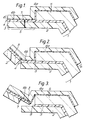
- Figure 1 shows the multi-layer bottom film 1 as comprising a lower portion 2 and an upper portion 3 separated by a weak point 4.
- the underside of the tray 5, in this case formed of HDPE, is covered by the lower film 1.
- the upper film 6 in this case of twin-layer construction, covers the top of the tray 5, and forms a vacuum skin pack with the product (not shown) on the tray. Furthermore, the upper film 6 projects laterally to be joined to the lower film 1 over a seal region S where the two films project beyond the rim of the tray.
- the upper film 6 has its lower or sealing layer 6 b of a material which readily seals to the upper portion 3 of the lower film 1. Its outer remaining layer 6 a may optionally include an oxygen barrier material.
- the lower film 1 has a pre-scored cut 7 which extends diagonally across one corner of the finished pack, i.e. close to a corner of the tray 5. This transverse cut can be seen in section in Figure 1.
- the edge of the tray is thus required to be sufficiently rigid and sharp to act as a cutting knife to help in rupturing the thin delaminated upper portion 3 of the lower film 1.
- the thickness of the upper portion 3 of the lower film 1 is much less than that of the lower portion 2 of the lower film 1 (i.e. the weak point 4 occurs near the bond between the lower and upper films 1 and 6, respectively).
- the structure of the multi-layer lower film 1 comprises:-
- the weak point is not always a pair of layers but may for example be the interface between a strength-imparting layer and a sealant layer which naturally exhibit a weak affinity for one another.
- the above general formula may equally give rise to a multi-layer film of many more than two layers such that there may be more than one layer in the strength-imparting layer, for example a strength-imparting bulk layer and a special barrier layer with or without appropriate adhesive ties between them, and equally the weak point may itself comprise additional layers necessary to give the desired weak bond which is to be weaker than the bond between the sealing layers of the upper and lower films.
- the "strength-imparting" layer may for example be polystyrene, nylon, ethylene vinyl acetate (EVA) or low density polyethylene (LDPE); if a special barrier layer is present this may, for example, comprise polyvinylidene chloride (PVDC), or nylon, or ethylene vinyl alcohol (EVOH); the sealing layers may, for example, be of an ionomer, or LDPE or EVA which may or may not be electronically cross-linked.
- PVDC polyvinylidene chloride
- EVOH ethylene vinyl alcohol
- the sealing layers may, for example, be of an ionomer, or LDPE or EVA which may or may not be electronically cross-linked.
- the package in accordance with the present invention can be used for containing ready-to-heat meals, which may be packaged either before or after heat treatment of the meal. It has been found that even after moist heat treatment the pack is securely sealed but nevertheless particularly easy to open.
- the rupturing action of the edge of the tray rim 5 is important in avoiding a situation where the delamination started at the weak point 4 in Figure 1 might continue at that same interface between the upper portion 3 and the lower portion 2 of the bottom film 1 across the whole package, in which case the tray 5 and the product will remain encapsulated between the upper film 6 and the delaminated upper portion 3 of the bottom film 1.
- the interface between the upper film 6 and the lower film 1 is at least four times stronger than the weak point bond, and preferably as much as ten times greater.
- the bond strength should be adequate for the pack to withstand the effects of heat treatment, for example immersion in a water bath at a temperature of up to 100°C for a considerable period (for example up to 45 minutes) without the weak point bond delaminating spontaneously.
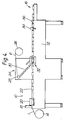
- Figure 4 illustrates a packaging apparatus which can be used for forming the packs of which details are shown in Figures 1 to 3.
- This apparatus 10 comprises a machine table 12 across which the first film 1 from a supply roll 14 is fed towards a delivery end 16 of the table 12.
- thermoforming station 20 At which the bottom film is formed into a generally tray-like configuration ready to receive the conforming trays 5 shown in Figures 1 to 3.
- the products 22 and the trays 5 are covered by the upper film 6 which is advanced from its supply roll 26 over a roller 28 and past radiant heaters 30 which pre-heat the film 6 to help it to bond to the lower film 1 on contact.
- the films 1 and 6 come together during entry of the pre-formed lower film 1, the trays 5 and the covering films 6 at a sealing chamber 32.
- the succession of now sealed packs moves onwards past a transverse severing station 34 at which the leading pack, or row of two or more side-by-side packs, is separated from the next successive pack or row of packs. Thence the packs pass to the longitudinal slitting station 36 at which the scrap along the margins of the films is removed and where there are various side-by-side packs in each row these are separated from one another.
Landscapes
- Engineering & Computer Science (AREA)
- Mechanical Engineering (AREA)
- Chemical & Material Sciences (AREA)
- Composite Materials (AREA)
- Packages (AREA)
- Auxiliary Devices For And Details Of Packaging Control (AREA)
- Control And Other Processes For Unpacking Of Materials (AREA)
- Packaging Of Annular Or Rod-Shaped Articles, Wearing Apparel, Cassettes, Or The Like (AREA)
Abstract
Description
- The present invention relates to a film package which can readily be opened without the use of cutting implements. Such packages are frequently termed "easy-open packs". The invention also relates to a method of forming such a package which, for example, is known from EP-A-0 328 245.
- In the past it has been known to insert a release sheet portion at the corner of a film pack as a way of disenabling the bonding action at that corner, or to use other means of weakening the bond between two packaging films, to facilitate starting delamination of the pack at the corner along the interface between two packaging sheets. Where the pack is to be subjected to heat treatment after sealing, these usual easy-open features are unsatisfactory as the seal would be inadequate.
- The present invention is concerned with a type of pack in which a product is placed on a tray and the assembly of product and tray is then totally enclosed within packaging films, such as one including a special barrier layer to improve the ability of the film to hinder or to exclude ingress of gas or moisture at both the side of the tray where the product rests, and the opposite side of the tray to preserve the packaged product. The term "barrier layer" is used to denote a layer of a film which is chosen for its especially good properties of gas impermeability.
- According to one aspect of the present invention there is provided a pack comprising:- a laminar support having at least one product thereon; a multi-layer first film covering the reverse side of the support i.e. the one other than that on which the or each product rests; and a second film covering the or each product and the side of the support on which it rests to encapsulate the product(s) against the support; characterised in that the first and second films project laterally beyond the perimeter of the support around its full extent and being sealed together; in that the bond strength of the bond between two layers of said first film close to the interface between the first and second films is lower than the bond strength between the first and second films at said interface, whereby delamination at said lower strength bond is possible and in that said support is more rigid than either of said first and second films.
- A second aspect of the present invention provides a method of forming an easy-open pack comprising:- placing at least one product on one side of a relatively rigid support; applying a multi-layer first film to the reverse side of the support; and covering the product and said one side of the support with a second film; characterised in that the first and second films each extend laterally beyond the perimeter of said support and are bonded to one another at the projecting part; and in that said first film has a bond strength between two adjacent layers close to the interface between the first and second films which is lower than the bond strength between said first and second films, and in that said support is more rigid than either of said first and second films.
- The effectiveness of the present invention relies on the fact that the strength of the sealing layers of the first and second films, on sealing the pack, is considerably higher than that of the bond between the portions of the first film at the weak point.
- In order that the present invention may more readily be understood the following description is given, merely by way of example, reference being made to the accompanying drawings, in which:-
- FIGURE 1 is a detail schematic view of a corner of a pack in accordance with the present invention at the start of the delamination of the. films during opening of the pack;
- FIGURE 2 is a view showing the pack of Figure 1 but after further delamination;
- FIGURE 3 shows the corner of the pack after rupture of the delaminated portion of the lower film and before removal of the cover film in its entirety; and
- FIGURE 4 is a schematic side view of packaging apparatus for forming a pack in accordance with the present invention.
- This invention is in particular concerned with a type of pack in which a tray, for example of high density polyethylene (HDPE) or polyester, has a product placed on it and the combination of the tray and the product finishes up enveloped between two films. These comprise (i) a first or bottom film, underneath the tray, of multi-layer composition, and (ii) a second or top film, above the tray and the product, which is sealed to an exposed portion of the lower film outboard of the rim of the tray. Preferably the upper film is itself of multi-layer construction.
- We now propose to "engineer" a weak point between the layers, or two of the layers, of the multi-layer bottom film, closer to the tray-contacting surface of that film than to the opposite surface which will be outermost in the finished pack, whereby the delamination between a minority upper portion of the bottom film and a majority lower portion of the same film can be initiated.
- As examples of the manner in which the weak point can be "engineered", one possibility would be for a bonding layer between two layers having little or no affinity for each other (for example a strength-imparting layer and a sealing layer) to give a bond which is weaker than the bond between the top and bottom films and preferably also weaker than any other bond between layers of the multi-layer bottom film. Delamination can be initiated between the minor thickness portion of the first film 1 including the sealing layer and the major thickness remainder of the first film at the "weak point" defined by the bonding layer. Another possibility will be for the structure of the bottom film to include direct contact between two layers which have some affinity for each other so as to bond together on contact but in a less permanent way than do other layers of the multi-layer film. It is within the scope of the present invention for other possibilities of providing a weak point in the structure of the bottom film to be used.
- The tray has a sharp edge to its rim, thus acting as a separating tool to assist in rupture of the minority film portion closer to the tray, in order to enable rupture of the part which projects beyond the tray rim from the part which is in register with the tray.
- Figure 1 shows the multi-layer bottom film 1 as comprising a
lower portion 2 and anupper portion 3 separated by aweak point 4. The underside of thetray 5, in this case formed of HDPE, is covered by the lower film 1. - The
upper film 6, in this case of twin-layer construction, covers the top of thetray 5, and forms a vacuum skin pack with the product (not shown) on the tray. Furthermore, theupper film 6 projects laterally to be joined to the lower film 1 over a seal region S where the two films project beyond the rim of the tray. - The
upper film 6 has its lower or sealinglayer 6b of a material which readily seals to theupper portion 3 of the lower film 1. Its outerremaining layer 6a may optionally include an oxygen barrier material. - In order to facilitate opening of the pack, the lower film 1 has a
pre-scored cut 7 which extends diagonally across one corner of the finished pack, i.e. close to a corner of thetray 5. This transverse cut can be seen in section in Figure 1. - The consumer then grasps the rim of the
tray 5 and, with the other hand, grasps the outer edge of the seal region S (embracing films 1 and 6) and pulls that edge region upwardly. This start of the tearing is shown in Figure 2 which shows then that at the same time the bottom film 1 begins to delaminate at theweak point 4. As delamination proceeds, the Figure 3 situation is arrived at where thesealing portion 3 of the lower film 1 has become ruptured at 8 by the edge of the rim of thetray 5, and at this stage the pack begins to open as thelower layer 6b of the upper film peels away from the rim of the tray. As this peeling action continues, the product is exposed for use. - The edge of the tray is thus required to be sufficiently rigid and sharp to act as a cutting knife to help in rupturing the thin delaminated
upper portion 3 of the lower film 1. In order to ensure that theupper portion 3 of the lower film 1 can rupture adjacent the edge of thetray rim 5, the thickness of theupper portion 3 of the lower film 1 is much less than that of thelower portion 2 of the lower film 1 (i.e. theweak point 4 occurs near the bond between the lower andupper films 1 and 6, respectively). - Other means of prompting delamination at the
weak point 4 may be employed, and one possibility would be to provide a projecting tab secured, for example adhesively, to the upper surface of theupper film 6 in order to allow that film to be peeled away from the lower film 1. With such an arrangement an optional second tab fastened to the underside of the lower film 1 may be used. These measures would render redundant thepre-score line 7 shown in Figure 1. For this delamination to occur, the bond between the or each tab and the film surface to which it is secured must be significantly greater than the bond strength at the weak point betweenportions - Generally, the structure of the multi-layer lower film 1 comprises:-

- It will of course be appreciated that in this general "formula" the weak point is not always a pair of layers but may for example be the interface between a strength-imparting layer and a sealant layer which naturally exhibit a weak affinity for one another. However, the above general formula may equally give rise to a multi-layer film of many more than two layers such that there may be more than one layer in the strength-imparting layer, for example a strength-imparting bulk layer and a special barrier layer with or without appropriate adhesive ties between them, and equally the weak point may itself comprise additional layers necessary to give the desired weak bond which is to be weaker than the bond between the sealing layers of the upper and lower films.
- The "strength-imparting" layer may for example be polystyrene, nylon, ethylene vinyl acetate (EVA) or low density polyethylene (LDPE); if a special barrier layer is present this may, for example, comprise polyvinylidene chloride (PVDC), or nylon, or ethylene vinyl alcohol (EVOH); the sealing layers may, for example, be of an ionomer, or LDPE or EVA which may or may not be electronically cross-linked.
- Should there be more than one weak bond in the structure of the lower film 1 having bond strengths of the same order of magnitude and less than the bond strength at any other inter-layer bonds, then of these weak bond strengths the one nearest the sealant layer (the
upper layer 3 of the lower film 1) will be the first to delaminate as the Figure 2 configuration is achieved. This is the bond which is referred to herein as the "engineered" weak point. - The package in accordance with the present invention can be used for containing ready-to-heat meals, which may be packaged either before or after heat treatment of the meal. It has been found that even after moist heat treatment the pack is securely sealed but nevertheless particularly easy to open.
- The rupturing action of the edge of the
tray rim 5 is important in avoiding a situation where the delamination started at theweak point 4 in Figure 1 might continue at that same interface between theupper portion 3 and thelower portion 2 of the bottom film 1 across the whole package, in which case thetray 5 and the product will remain encapsulated between theupper film 6 and the delaminatedupper portion 3 of the bottom film 1. - By trimming the package so that a constant projection of the bottom film 1 beyond the edge of the rim of the
tray 5 occurs around the whole of the tray, the opening force required for the delamination of Figure 1 to begin is known and is constant around the whole package. - It is important for the resistance to tearing of the layer or layers constituting the
upper portion 3 of the bottom film 1 to be low enough for rupture of theupper portion 3 by the cutting knife effect of the edge of thetray rim 5 to succeed. - In order to achieve a reliable delamination at the
weak point 4, it is advantageous for the interface between theupper film 6 and the lower film 1 to be at least four times stronger than the weak point bond, and preferably as much as ten times greater. However, it is equally important that at the weak point the bond strength should be adequate for the pack to withstand the effects of heat treatment, for example immersion in a water bath at a temperature of up to 100°C for a considerable period (for example up to 45 minutes) without the weak point bond delaminating spontaneously. - By way of example, Figure 4 illustrates a packaging apparatus which can be used for forming the packs of which details are shown in Figures 1 to 3. This
apparatus 10 comprises a machine table 12 across which the first film 1 from asupply roll 14 is fed towards adelivery end 16 of the table 12. - First of all the film 1 passes a
corner cutting station 18 at which the pre-scored cuts (7 in Figure 1) are formed, and then it proceeds to athermoforming station 20 at which the bottom film is formed into a generally tray-like configuration ready to receive the conformingtrays 5 shown in Figures 1 to 3. - These
trays 5, together with theproduct articles 22 thereon are introduced into the trays defined by the film 1 and with it they then enter asealing station 24. - In the
sealing station 24 theproducts 22 and thetrays 5 are covered by theupper film 6 which is advanced from itssupply roll 26 over aroller 28 and pastradiant heaters 30 which pre-heat thefilm 6 to help it to bond to the lower film 1 on contact. Thefilms 1 and 6 come together during entry of the pre-formed lower film 1, thetrays 5 and the coveringfilms 6 at asealing chamber 32. - On leaving the
sealing chamber 32, the succession of now sealed packs moves onwards past atransverse severing station 34 at which the leading pack, or row of two or more side-by-side packs, is separated from the next successive pack or row of packs. Thence the packs pass to thelongitudinal slitting station 36 at which the scrap along the margins of the films is removed and where there are various side-by-side packs in each row these are separated from one another.
Claims (8)
- A pack comprising:- a laminar support (5) having at least one product (22) thereon; a multi-layer first film (2, 3) covering the reverse side of the support i.e. the one other than that on which the or each product rests; and a second film (6a, 6b) covering the or each product and the side of the support on which it rests to encapsulate the product(s) against the support;
characterised in that the first and second films project laterally beyond the perimeter of the support around its full extent and being sealed together; in that the bond strength of the bond between two layers (2 and 3) of said first film close to the interface (3/6b) between the first and second films is lower than the bond strength between the first (2, 3) and second (6a, 6b) films at said interface, whereby delamination at said lower strength bond is possible and in that said support is more rigid than either of said first and second films. - A pack according to claim 1, characterised in that said support is a tray (5) having a rim with sharp edges for initiating a tear in said portion of the first film (2, 3) upon delamination of said first film.
- A pack according to either of the preceding claims, characterised in that the support is sufficiently rigid to rupture the delaminated part of said first film comprising the layers thereof between said bond and said interface.
- A pack according to any one of claims 1 to 3, characterised in that the or each product (22) is all or part of a ready-to-heat meal which has been heat treated in situ in the pack.
- A method of forming an easy-open pack comprising:- placing at least one product on one side of a relatively rigid support; applying a multi-layer first film to the reverse side of the support; and covering the product and said one side of the support with a second film; characterised in that the first and second films each extend laterally beyond the perimeter of said support and are bonded to one another at the projecting part; and in that said first film has a bond strength between two adjacent layers close to the interface between the first and second films which is lower than the bond strength between said first and second films, and in that said support is more rigid than either of said first and second films.
- A method according to claim 5, characterised by further including the step of cutting said first film across and adjacent a corner of the support, to facilitate delamination at said bond of lower strength.
- A method according to either of claims 5 and 6, characterised in that the support, with its product thereon, and enclosed within the first and second films, is subjected to heat treatment before and after storage and display.
- A method according to any one of claims 5 to 7, characterised in that said at least one product is all or part of a ready-to-heat meal.
Priority Applications (1)
| Application Number | Priority Date | Filing Date | Title |
|---|---|---|---|
| AT90306786T ATE100407T1 (en) | 1989-08-29 | 1990-06-21 | EASY-TO-OPEN PACKAGING AND METHOD OF PRODUCTION. |
Applications Claiming Priority (2)
| Application Number | Priority Date | Filing Date | Title |
|---|---|---|---|
| GB8919525 | 1989-08-29 | ||
| GB8919525A GB2235912A (en) | 1989-08-29 | 1989-08-29 | Easy-open package and method of forming the same |
Publications (2)
| Publication Number | Publication Date |
|---|---|
| EP0415520A1 EP0415520A1 (en) | 1991-03-06 |
| EP0415520B1 true EP0415520B1 (en) | 1994-01-19 |
Family
ID=10662216
Family Applications (1)
| Application Number | Title | Priority Date | Filing Date |
|---|---|---|---|
| EP90306786A Expired - Lifetime EP0415520B1 (en) | 1989-08-29 | 1990-06-21 | Easy-open package and method of forming the same |
Country Status (6)
| Country | Link |
|---|---|
| EP (1) | EP0415520B1 (en) |
| JP (1) | JP2918658B2 (en) |
| AT (1) | ATE100407T1 (en) |
| CA (1) | CA2024164A1 (en) |
| DE (1) | DE69006140T2 (en) |
| GB (1) | GB2235912A (en) |
Families Citing this family (5)
| Publication number | Priority date | Publication date | Assignee | Title |
|---|---|---|---|---|
| DE19751428A1 (en) * | 1996-11-26 | 1998-05-28 | Danubia Petrochem Deutschland | Childproof packaging for pharmaceutical or detergent tablets in deep drawn container |
| DE19743485A1 (en) * | 1997-10-01 | 1999-04-15 | Lohmann Therapie Syst Lts | Childproof pack for comparatively large and pressure-sensitive therapeutic products such as a transdermal therapeutic system |
| EP1774932B1 (en) * | 2005-10-11 | 2015-08-26 | ConvaTec Technologies Inc. | Ostomy coupling |
| US20110229610A1 (en) * | 2008-12-01 | 2011-09-22 | Cascades Canada Inc. | Anti-leak meat pack, food packaging tray therefore, and associated methods |
| CN106541430B (en) * | 2015-09-23 | 2018-05-08 | 上海沛鑫包装科技有限公司 | With the bottleneck sealer manufacture method for tearing head and its tear a molding machine |
Family Cites Families (8)
| Publication number | Priority date | Publication date | Assignee | Title |
|---|---|---|---|---|
| US3188215A (en) * | 1963-04-09 | 1965-06-08 | Grace W R & Co | Frozen food package and method for producing same |
| GB1241223A (en) * | 1967-07-11 | 1971-08-04 | Standard Packaging Corp | Improvements in packages |
| US3780187A (en) * | 1968-11-12 | 1973-12-18 | Mayer & Co Inc O | Heat-and-serve packages for precooked sausage and the like |
| US3655503A (en) * | 1969-01-13 | 1972-04-11 | Crown Zellerbach Corp | Package of composite film with peelable, heatsealable surfaces |
| US4615926A (en) * | 1984-07-20 | 1986-10-07 | American Can Company | Film and package having strong seals and a modified ply-separation opening |
| DE3504463A1 (en) * | 1985-02-09 | 1986-08-14 | W.R. Grace & Co., New York, N.Y. | EASILY OPENABLE PACKING AND METHOD FOR THE PRODUCTION THEREOF |
| JPS6378A (en) * | 1986-06-18 | 1988-01-05 | 出光石油化学株式会社 | Simple beer vessel |
| US4889731A (en) * | 1988-02-12 | 1989-12-26 | W. R. Grace & Co.-Conn. | Package having peelable film |
-
1989
- 1989-08-29 GB GB8919525A patent/GB2235912A/en not_active Withdrawn
-
1990
- 1990-06-21 EP EP90306786A patent/EP0415520B1/en not_active Expired - Lifetime
- 1990-06-21 AT AT90306786T patent/ATE100407T1/en not_active IP Right Cessation
- 1990-06-21 DE DE69006140T patent/DE69006140T2/en not_active Expired - Lifetime
- 1990-08-14 JP JP2214887A patent/JP2918658B2/en not_active Expired - Lifetime
- 1990-08-28 CA CA002024164A patent/CA2024164A1/en not_active Abandoned
Also Published As
| Publication number | Publication date |
|---|---|
| DE69006140T2 (en) | 1994-08-04 |
| ATE100407T1 (en) | 1994-02-15 |
| JPH03133770A (en) | 1991-06-06 |
| CA2024164A1 (en) | 1991-03-01 |
| JP2918658B2 (en) | 1999-07-12 |
| EP0415520A1 (en) | 1991-03-06 |
| DE69006140D1 (en) | 1994-03-03 |
| GB8919525D0 (en) | 1989-10-11 |
| GB2235912A (en) | 1991-03-20 |
Similar Documents
| Publication | Publication Date | Title |
|---|---|---|
| JP4024868B2 (en) | Laminate with delaminated coextruded multilayer film and package made from the laminate | |
| EP0946396B1 (en) | Package having a dual-film lid comprising a gas-impermeable film and a delaminatable, gas-permeable film, and packaging method | |
| CA2939933C (en) | Scored and labeled resealable packaging | |
| AU589392B2 (en) | Containers | |
| EP0328245B1 (en) | Package having peelable film | |
| EP1340693A1 (en) | Easy open package | |
| JPH09323759A (en) | Device for opening container lid, having rim being sealed with capsule | |
| US4766018A (en) | Readily peelable, sterilizable packages | |
| US5887747A (en) | Method of closing off the mouth of a container, a container with a closure of this kind and a material for manufacturing the closure | |
| CA2060120A1 (en) | Package | |
| CA2256984C (en) | Peel mechanism for peelable barrier film for vacuum skin packages and the like | |
| US20210347518A1 (en) | A Recyclable Moulded Pulp Container | |
| EP0415520B1 (en) | Easy-open package and method of forming the same | |
| JP3867474B2 (en) | Easy-open composite film and packaging container | |
| CN108367541B (en) | Sealing foil with pull tab | |
| WO1998017546A1 (en) | Package having peel initiation mechanism | |
| JP2684205B2 (en) | Container with lid made of laminated material | |
| MXPA99007797A (en) | Sealed containers with tabs and method to prepare |
Legal Events
| Date | Code | Title | Description |
|---|---|---|---|
| PUAI | Public reference made under article 153(3) epc to a published international application that has entered the european phase |
Free format text: ORIGINAL CODE: 0009012 |
|
| AK | Designated contracting states |
Kind code of ref document: A1 Designated state(s): AT BE CH DE DK ES FR GB GR IT LI LU NL SE |
|
| 17P | Request for examination filed |
Effective date: 19910508 |
|
| 17Q | First examination report despatched |
Effective date: 19930128 |
|
| GRAA | (expected) grant |
Free format text: ORIGINAL CODE: 0009210 |
|
| AK | Designated contracting states |
Kind code of ref document: B1 Designated state(s): AT BE CH DE DK ES FR GB GR IT LI LU NL SE |
|
| PG25 | Lapsed in a contracting state [announced via postgrant information from national office to epo] |
Ref country code: IT Free format text: LAPSE BECAUSE OF FAILURE TO SUBMIT A TRANSLATION OF THE DESCRIPTION OR TO PAY THE FEE WITHIN THE PRE;WARNING: LAPSES OF ITALIAN PATENTS WITH EFFECTIVE DATE BEFORE 2007 MAY HAVE OCCURRED AT ANY TIME BEFORE 2007. THE CORRECT EFFECTIVE DATE MAY BE DIFFERENT FROM THE ONE RECORDED.SCRIBED TIME-LIMIT Effective date: 19940119 Ref country code: GR Free format text: LAPSE BECAUSE OF FAILURE TO SUBMIT A TRANSLATION OF THE DESCRIPTION OR TO PAY THE FEE WITHIN THE PRESCRIBED TIME-LIMIT Effective date: 19940119 Ref country code: AT Effective date: 19940119 Ref country code: DK Effective date: 19940119 Ref country code: SE Effective date: 19940119 |
|
| REF | Corresponds to: |
Ref document number: 100407 Country of ref document: AT Date of ref document: 19940215 Kind code of ref document: T |
|
| REF | Corresponds to: |
Ref document number: 69006140 Country of ref document: DE Date of ref document: 19940303 |
|
| PG25 | Lapsed in a contracting state [announced via postgrant information from national office to epo] |
Ref country code: ES Free format text: LAPSE BECAUSE OF FAILURE TO SUBMIT A TRANSLATION OF THE DESCRIPTION OR TO PAY THE FEE WITHIN THE PRESCRIBED TIME-LIMIT Effective date: 19940430 |
|
| ET | Fr: translation filed | ||
| PGFP | Annual fee paid to national office [announced via postgrant information from national office to epo] |
Ref country code: GB Payment date: 19940613 Year of fee payment: 5 |
|
| PGFP | Annual fee paid to national office [announced via postgrant information from national office to epo] |
Ref country code: SE Payment date: 19940615 Year of fee payment: 5 |
|
| PGFP | Annual fee paid to national office [announced via postgrant information from national office to epo] |
Ref country code: ES Payment date: 19940627 Year of fee payment: 5 |
|
| PGFP | Annual fee paid to national office [announced via postgrant information from national office to epo] |
Ref country code: DK Payment date: 19940630 Year of fee payment: 5 Ref country code: LU Payment date: 19940630 Year of fee payment: 5 |
|
| EPTA | Lu: last paid annual fee | ||
| PLBE | No opposition filed within time limit |
Free format text: ORIGINAL CODE: 0009261 |
|
| STAA | Information on the status of an ep patent application or granted ep patent |
Free format text: STATUS: NO OPPOSITION FILED WITHIN TIME LIMIT |
|
| 26N | No opposition filed | ||
| PG25 | Lapsed in a contracting state [announced via postgrant information from national office to epo] |
Ref country code: LU Free format text: LAPSE BECAUSE OF NON-PAYMENT OF DUE FEES Effective date: 19950621 Ref country code: GB Effective date: 19950621 |
|
| GBPC | Gb: european patent ceased through non-payment of renewal fee |
Effective date: 19950621 |
|
| REG | Reference to a national code |
Ref country code: FR Ref legal event code: TP |
|
| REG | Reference to a national code |
Ref country code: CH Ref legal event code: PUE Owner name: W. R. GRACE & CO.-CONN. TRANSFER- CRYOVAC, INC. |
|
| PGFP | Annual fee paid to national office [announced via postgrant information from national office to epo] |
Ref country code: NL Payment date: 20060604 Year of fee payment: 17 |
|
| NLV4 | Nl: lapsed or anulled due to non-payment of the annual fee |
Effective date: 20080101 |
|
| PG25 | Lapsed in a contracting state [announced via postgrant information from national office to epo] |
Ref country code: NL Free format text: LAPSE BECAUSE OF NON-PAYMENT OF DUE FEES Effective date: 20080101 |
|
| PGFP | Annual fee paid to national office [announced via postgrant information from national office to epo] |
Ref country code: FR Payment date: 20090617 Year of fee payment: 20 |
|
| PGFP | Annual fee paid to national office [announced via postgrant information from national office to epo] |
Ref country code: CH Payment date: 20090625 Year of fee payment: 20 |
|
| PGFP | Annual fee paid to national office [announced via postgrant information from national office to epo] |
Ref country code: DE Payment date: 20090629 Year of fee payment: 20 |
|
| PGFP | Annual fee paid to national office [announced via postgrant information from national office to epo] |
Ref country code: BE Payment date: 20090715 Year of fee payment: 20 |
|
| BE20 | Be: patent expired |
Owner name: *CRYOVAC INC. Effective date: 20100621 |
|
| REG | Reference to a national code |
Ref country code: CH Ref legal event code: PL |
|
| PG25 | Lapsed in a contracting state [announced via postgrant information from national office to epo] |
Ref country code: DE Free format text: LAPSE BECAUSE OF EXPIRATION OF PROTECTION Effective date: 20100621 |