EP0415460A2 - Vorrichtung in der Trockenpartie einer Papiermaschine - Google Patents
Vorrichtung in der Trockenpartie einer Papiermaschine Download PDFInfo
- Publication number
- EP0415460A2 EP0415460A2 EP90116908A EP90116908A EP0415460A2 EP 0415460 A2 EP0415460 A2 EP 0415460A2 EP 90116908 A EP90116908 A EP 90116908A EP 90116908 A EP90116908 A EP 90116908A EP 0415460 A2 EP0415460 A2 EP 0415460A2
- Authority
- EP
- European Patent Office
- Prior art keywords
- cylinder
- web
- support fabric
- space
- free run
- Prior art date
- Legal status (The legal status is an assumption and is not a legal conclusion. Google has not performed a legal analysis and makes no representation as to the accuracy of the status listed.)
- Granted
Links
- 238000001035 drying Methods 0.000 title claims abstract description 14
- 239000004744 fabric Substances 0.000 claims abstract description 62
- 230000000087 stabilizing effect Effects 0.000 claims abstract description 3
- 238000007789 sealing Methods 0.000 claims description 9
- 230000000694 effects Effects 0.000 description 5
- 238000007664 blowing Methods 0.000 description 3
- 238000010276 construction Methods 0.000 description 3
- 206010040954 Skin wrinkling Diseases 0.000 description 1
- 230000000875 corresponding effect Effects 0.000 description 1
- 230000001419 dependent effect Effects 0.000 description 1
- 238000000034 method Methods 0.000 description 1
- 239000002344 surface layer Substances 0.000 description 1
Images
Classifications
-
- D—TEXTILES; PAPER
- D21—PAPER-MAKING; PRODUCTION OF CELLULOSE
- D21F—PAPER-MAKING MACHINES; METHODS OF PRODUCING PAPER THEREON
- D21F5/00—Dryer section of machines for making continuous webs of paper
- D21F5/02—Drying on cylinders
- D21F5/04—Drying on cylinders on two or more drying cylinders
- D21F5/042—Drying on cylinders on two or more drying cylinders in combination with suction or blowing devices
Definitions
- the present invention relates to a device in the drying section of a paper machine as defined in the preamble of claim 1.
- the drying section of a paper machine comprises generally two tiers of drying cylinders through which the web is passed, guided by a support fabric which carries it, the web and the support fabric running along a tortuous path alternately between the cylinders of the first tier and the second tier.
- the drying cylinders of the first tier the web lies against the circumferential surface of the cylinder and the support fabric is situated on top of it, and at the cylinders of the second tier the web lies outermost while the support fabric lies against the circumferential surface.
- the above mentioned boxes comprise as a rule a chamber connected to a source of pressurized medium, such as air, as well as a nozzle slot in the wall of the chamber for producing the air stream affecting the positive and negative pressures within the wedge-like spaces.
- a source of pressurized medium such as air
- nozzle slots are directed either against the directions of movements of the support fabric or against the circumferential surfaces of the cylinders. Hence, great blowing efficiency is necessary in order to produce a satisfactory result.
- the purpose of the invention is to provide a device which has not the drawbacks caused by the technique described hereinabove.
- the device according to the invention is mainly characterised by the features disclosed in the characterising portion of claim 1.
- the appended dependent claims 2 to 8 show some advantageous features of embodiments of the device according to the invention.
- the nozzle slot is directed preferably at an angle of 45° to 90° with respect to said free run.
- the device can easily be accommodated within the narrow pocket formed by two drying cylinders of the first tier and a drying cylinder of the second tier by using the configuration where the outer chamber wall facing the support fabric bounds the space situated between the ejector and said free run.
- An ejector structure can be created in the simplest way by forming the nozzle slot by means of two nozzle slots situated adjacent to each other substantially in parallel with each other, whereby the ejector structure is formed between the adjacent edges of the nozzle slots. The effect of the space between the support fabric and ejector can be improved by closing the space by sealing means.
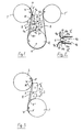
- Fig. 1 shows a part of the drying section of the paper machine.
- the drying section comprises upper cylinders 1 and lower cylinders 2 aligned in two tiers.
- a web W and a support fabric F carrying it, a dryer felt, travel one on top of the other along a tortuous path between the upper cylinders and the lower cylinders.
- the upper cylinders constitute the first tier, where the paper web W to be dried lies against the circumferential surface of the cylinders 1 and the support fabric F, the dryer felt, lies topmost supporting the web against the circumferential surface of the cylinder.
- the lower cylinders constitute the other tier, where the support fabric F lies against the circumferential surface of the cylinders 2 and the web W is situated topmost.
- the support fabric F and the web W leave a first tier cylinder 1, the first cylinder, for a second tier cylinder, the second dryer cylinder 2, at which the support fabric F is situated against the circumferential surface of the cylinder and the web travels on top of the support fabric.
- the web along with the support fabric travel as a free run, which portion has been indicated by reference numeral 8.
- a wedge-like space between the free run 8 and the circumferential surface of the cylinder 1 at the location where the web and the support fabric depart is indicated by letter K-. This space is subjected to negative pressure induced by the air streams caused by the movement of the cylinder 1 and the free run 8.
- a wedge-like space in the point of junction of the web with the support fabric and the second cylinder 2, situated between the free run 8 and the cylinder 2, is indicated by letter K+.
- This space is subjected to positive pressure due to the movement of the above mentioned members.
- a device 3 according to the invention is positioned at the height of the free run 8 on the side of the support fabric F.
- the device comprises a chamber 4 connected to a source S of pressurized medium, such as pressurized air, and it comprises further a nozzle slot 5 in the chamber wall.
- the nozzle slot 5 is directed at an angle of e.g. 45 to 90° with respect to the free run 8 of the web W and the support fabric F, that is in a manner that the air stream issuing from the nozzle slot is directed away from the web and the support fabric at an angle to the free run 8.
- the air stream which is denoted by arrows in the Figure, is moreover directed towards an area 9, which is situated outside the wedge-like space K+ bounded by the cylinder 2 on the side of the device 3 and by the abovementioned free run 8. Hence, the air stream does not need to overcome the currents caused by the rotatory movement of the cylinder.
- ejector 6 for ejecting air from a space 7 with the help of said air stream issuing from the nozzle slot 5.
- the space 7 is situated behind the ejector 6 and it is bounded by said free run 8.
- the negative pressure induced in the space 7 can thus have an effect on the positive pressure of the wedge-like space K+ on the same side of the free run 8, as well as on the subpressure in the wedge-like space K- on the other side of the free run 8, thus stabilizing the run of the web W.
- the second cylinder 2 After the web W and the support fabric F have travelled round the second cylinder 2 within a predetermined sector, which usually is over 180°, they leave it to form again a free run 8 and join again a cylinder situated in the same tier as the first cylinder 1. Said cylinder is indicated by reference numeral 1′ in the Figure.
- the device 3 is thus situated within a pocket-like space bounded by the free run 8 arriving at the second cylinder 2, by the circumferential surface of said second cylinder 2 and by the free run 8 leaving the second cylinder 2.
- This space can be equipped for example with baffle plates for guiding the air stream issuing from the nozzle slot 5 further through the space between the first tier cylinders 1 and 1′.
- the chamber 4 is constituted of two chambers 4′ and 4 ⁇ , which are situated along the width of the web to be dried perpendicularly to the direction of travel of the free run 8. Both chambers are connected in a suitable fashion, for example at their ends, to the abovementioned source of pressurized air and they comprise each a nozzle slot 10 for the outlet of air. The nozzle slots 10 are situated adjacent to each other and form together the nozzle slot 5 directed in the abovementioned manner.
- the outer wall 4a of each of the chambers 4′ and 4 ⁇ faces the support fabric F, bounding in this way substantially the free space 7 between the free run 8 and the ejector 6.
- edges of the walls 4a of both chambers which are in the proximity of each other turn approximately at the mid portion of the free run 8 away from it, and in said direction they form a converging slot 6, which constitutes the abovementioned ejector.
- the lower edge 10a of the wall 4a of the upper chamber 4′ turning away forms in the same time one of the edges of the nozzle slot 10 of the upper chamber.
- the upper edge of the wall 4a of the lower chamber 4 ⁇ turning away forms in the same time the other edge 10a of the nozzle slot 10 of this chamber.
- a converging flow slot 6 for the air stream taking place away from the space 7 is thus formed between the adjacent edges 10a of the nozzle slots 10 in said separate chambers.
- the chambers 4′ and 4 ⁇ further have outer walls 4b lying opposite to each other.
- the edges 10b of said walls 4b directed towards the free run 8 each form the other edge of the nozzle slot 10 of the respective chamber. Said edge protrudes in both nozzle slots slightly beyond the opposite edge 10a of the nozzle slot, as seen in a plane which is parallel to the plane of the free run 8.
- the outer walls 4b facing each other diverge from each other starting from the nozzle slots 10 and form in this way therebetween a flow path widening in the flow direction for the flow issuing from the nozzle slots 10 and the ejector 6.
- Said flow enters into the space 9 at a location, which is outside a plane which is tangent to the circumferential surface of the cylinder 2 at the midpoint of a sector thereof free from the web and the support fabric.
- the chamber front walls 4d bounding the chambers towards the space 9 join said opposite walls 4b at the remote ends of the walls 4b, as seen in the flow direction.
- the lower wall 4c following in an arcuate configuration the circumferential surface of the cylinder joins the front wall 4d.
- the lower wall 4c is thus situated between the rear wall 4a and the front wall 4d.
- the upper wall 4c interconnecting the front wall 4d and the rear wall 4a joins the upper edge of the front wall 4d of the upper chamber 4′.
- the upper wall 4c is situated approximately at the height where the free run 8 leaves the cylinder 1.
- the construction of the device as far as the ejector and the nozzle slots is concerned is shown in a larger scale in Fig. 2.
- Fig. 1 further shows, how the space 7 is closed by means of a sealing means 7′ fixed on one of the outer walls of the upper chamber 4′.
- the sealing means 7′ is in contact with the support fabric F and is situated preferably at the location where the support fabric along with the web leave the cylinder 1 or before that location.
- the space 7 is at the opposite end thereof closed with a similar sealing means 7 ⁇ situated between the outer wall of the lower chamber 4 ⁇ and the circumferential surface of the second cylinder 2 and being in contact with said surface.
- the sealing means can be any kind of previously known sealing means, for example mechanical sealing members, the purpose of which is to prevent the surface layer streams induced by the support fabric and the cylinders from entering into space 7, which phenomenon would impair the effect of the ejector 6.
- Fig. 3 shows a realization of the device 3 in accordance with the invention.
- the situation of the chambers, the nozzle slots and the ejector with respect of the free run of the web W and the support fabric F is similar to that of Fig. 1.
- a difference lies in that in this case the cylinder of the second tier of dryer cylinders is the first cylinder 1 as seen in the direction of travel of the web and the support fabric.
- the web W travels on top of the support fabric F lying against the circumferential surface of the cylinder 1, whereafter they leave the first cylinder 1 and after the free run 8 join to a cylinder of the first tier of dryer cylinders, in this case the second cylinder 2, on which the web W is carried against the circumferential surface of the cylinder and the support fabric F lies topmost.
- the wedge-like space situated on the side of the support fabric F between the free run 8 and the cylinder 1 is the space K- where negative pressure prevails
- the space between the second cylinder 2 on the side of the web is the wedge-like space K+ where positive pressure prevails.
- the device 3 is situated in the same manner on the side of the support fabric F at the height of said free run 8, and also in this case the space 7 situated between the chambers 4′ and 4 ⁇ and the support fabric F is affected by means of the ejector 6. Because at this location usually a smaller effect on the spaces K+ and K- is needed, the space 7 is not closed with sealing means of Fig. 1, but the space 7 is open both between the first cylinder 1 and the lower chamber 4 ⁇ and between the second cylinder 2 and the upper chamber 4′.
- the drying section can comprise, in addition to the actual dryer cylinders, also other cylinders, so-called reversing rollers, which are not heatable, but are used for reversing the travel of the web and the support fabric into an opposite direction. They can be situated in the same locations as the cylinders 1 and 2 of Figs. 1 and 3. It is apparent that the invention is suitable for use also in the drying sections comprising such cylinders.
Landscapes
- Drying Of Solid Materials (AREA)
- Paper (AREA)
Applications Claiming Priority (2)
| Application Number | Priority Date | Filing Date | Title |
|---|---|---|---|
| FI894145A FI82958C (fi) | 1989-09-01 | 1989-09-01 | Anordning vid ett torkparti av en pappersmaskin. |
| FI894145 | 1989-09-01 |
Publications (3)
| Publication Number | Publication Date |
|---|---|
| EP0415460A2 true EP0415460A2 (de) | 1991-03-06 |
| EP0415460A3 EP0415460A3 (en) | 1991-09-18 |
| EP0415460B1 EP0415460B1 (de) | 1995-02-01 |
Family
ID=8528928
Family Applications (1)
| Application Number | Title | Priority Date | Filing Date |
|---|---|---|---|
| EP90116908A Expired - Lifetime EP0415460B1 (de) | 1989-09-01 | 1990-09-03 | Vorrichtung in der Trockenpartie einer Papiermaschine |
Country Status (5)
| Country | Link |
|---|---|
| US (1) | US5086571A (de) |
| EP (1) | EP0415460B1 (de) |
| CA (1) | CA2024398C (de) |
| DE (1) | DE69016536T2 (de) |
| FI (1) | FI82958C (de) |
Cited By (2)
| Publication number | Priority date | Publication date | Assignee | Title |
|---|---|---|---|---|
| EP0826820A2 (de) * | 1996-08-29 | 1998-03-04 | Voith Sulzer Papiermaschinen GmbH | Maschine zur Herstellung einer Materialbahn |
| WO2009129056A1 (en) * | 2008-04-18 | 2009-10-22 | Honeywell International Inc. | Sheet stabilizer with dual inline machine direction air clamps and backsteps |
Families Citing this family (15)
| Publication number | Priority date | Publication date | Assignee | Title |
|---|---|---|---|---|
| DE4141296A1 (de) * | 1991-12-14 | 1993-06-17 | Voith Gmbh J M | Vorrichtung zur abnahme einer bahn von einem trockenzylinder |
| FI95732C (fi) * | 1992-01-13 | 1996-03-11 | Valmet Paperikoneet Oy | Laite paperikoneen kuivatusosassa |
| DE19544881A1 (de) * | 1995-12-01 | 1997-06-12 | Voith Sulzer Papiermasch Gmbh | Maschine zur Herstellung einer kontinuierlichen Bahn |
| DE29601543U1 (de) * | 1996-01-30 | 1996-03-28 | Voith Sulzer Papiermaschinen GmbH, 89522 Heidenheim | Vorrichtung zum Führen einer Faserstoffbahn in einer einreihigen Trockenpartie |
| US5704082A (en) * | 1996-11-26 | 1998-01-06 | Smith; Catherine V. | Anchor pin for dust ruffle |
| US5851357A (en) * | 1997-03-03 | 1998-12-22 | Valmet, Inc. | Combination saveall and blowbox system |
| US6260287B1 (en) | 1997-08-08 | 2001-07-17 | Peter Walker | Wet web stability method and apparatus |
| US5881472A (en) * | 1997-10-22 | 1999-03-16 | Beloit Technologies, Inc. | Ventilator apparatus for inhibiting flutter in a web dryer |
| US6908532B2 (en) * | 1999-06-01 | 2005-06-21 | Voith Sulzer Papiermaschinen Gmbh | Press belt |
| US6513263B2 (en) | 2000-10-06 | 2003-02-04 | Enerquin Air Inc. | Ventilator for offset pocket and method of ventilating the same |
| US6484418B1 (en) | 2000-11-06 | 2002-11-26 | Kimberly-Clark Worldwide, Inc. | Yankee drying hood and method comprising angled impingement nozzles |
| US6412192B1 (en) | 2001-01-30 | 2002-07-02 | Enerquin Air Inc. | Device and method for ventilating an offset pocket space in a papermaking machine |
| US6725569B2 (en) | 2001-01-30 | 2004-04-27 | Enerquin Air Inc. | Device and method for ventilating an offset pocket space in a papermaking machine |
| FI120005B (fi) * | 2001-03-06 | 2009-05-29 | Metso Paper Inc | Sovitelma paperikoneen kuivatusosalla |
| US8176650B2 (en) * | 2005-12-13 | 2012-05-15 | Kimberly-Clark Worldwide, Inc. | Method for warming up or cooling down a through-air dryer |
Citations (4)
| Publication number | Priority date | Publication date | Assignee | Title |
|---|---|---|---|---|
| US4359828A (en) * | 1979-11-05 | 1982-11-23 | Weyerhaeuser Company | Vacuum box for use in high speed papermaking |
| DE3220074A1 (de) * | 1982-05-28 | 1983-12-01 | J.M. Voith Gmbh, 7920 Heidenheim | Trockenpartie einer papiermaschine |
| US4551203A (en) * | 1984-04-02 | 1985-11-05 | Valmet Oy | Method and arrangement for guiding a paper web from the press section to the drying section |
| DE3706542A1 (de) * | 1987-02-28 | 1988-09-08 | Voith Gmbh J M | Luftleitkasten fuer die trockenpartie einer schnellaufenden papiermaschine |
Family Cites Families (9)
| Publication number | Priority date | Publication date | Assignee | Title |
|---|---|---|---|---|
| DE3236576C2 (de) * | 1982-10-02 | 1988-03-24 | J.M. Voith Gmbh, 7920 Heidenheim | Luftleitkasten für die Trockenpartie einer Papiermaschine |
| DE3344217A1 (de) * | 1983-12-07 | 1985-06-20 | J.M. Voith Gmbh, 7920 Heidenheim | Vorrichtung zum ueberfuehren einer papierbahn von der pressen- in die trockenpartie einer papiermaschine |
| FI73259C (fi) * | 1985-09-13 | 1987-09-10 | Valmet Oy | Foerfarande och anordning i cylindertorken av en pappersmaskin |
| BR8607250A (pt) * | 1986-02-21 | 1988-12-06 | Beloit Corp | Prevencao da trepidacao de folha em secadores de papel |
| US4698919A (en) * | 1986-04-08 | 1987-10-13 | Beloit Corp. | Apparatus for assisting the transfer of a web to a drying section |
| EP0302051B1 (de) * | 1986-04-08 | 1990-02-07 | Beloit Corporation | Blaskasten für trockner |
| DE3739338C2 (de) * | 1987-11-20 | 1995-09-07 | Voith Gmbh J M | Luftleitkasten zum Stabilisieren des Laufs einer Warenbahn, insbesondere einer Papierbahn |
| US4821429A (en) * | 1987-11-30 | 1989-04-18 | J. M. Voith, Gmbh | Air guide box for stabilizing the run of a web, for instance a paper web |
| DE3807857A1 (de) * | 1988-03-10 | 1989-09-28 | Voith Gmbh J M | Trockenpartie |
-
1989
- 1989-09-01 FI FI894145A patent/FI82958C/fi active IP Right Grant
-
1990
- 1990-08-30 US US07/574,680 patent/US5086571A/en not_active Expired - Lifetime
- 1990-08-31 CA CA002024398A patent/CA2024398C/en not_active Expired - Lifetime
- 1990-09-03 EP EP90116908A patent/EP0415460B1/de not_active Expired - Lifetime
- 1990-09-03 DE DE69016536T patent/DE69016536T2/de not_active Expired - Fee Related
Patent Citations (4)
| Publication number | Priority date | Publication date | Assignee | Title |
|---|---|---|---|---|
| US4359828A (en) * | 1979-11-05 | 1982-11-23 | Weyerhaeuser Company | Vacuum box for use in high speed papermaking |
| DE3220074A1 (de) * | 1982-05-28 | 1983-12-01 | J.M. Voith Gmbh, 7920 Heidenheim | Trockenpartie einer papiermaschine |
| US4551203A (en) * | 1984-04-02 | 1985-11-05 | Valmet Oy | Method and arrangement for guiding a paper web from the press section to the drying section |
| DE3706542A1 (de) * | 1987-02-28 | 1988-09-08 | Voith Gmbh J M | Luftleitkasten fuer die trockenpartie einer schnellaufenden papiermaschine |
Cited By (5)
| Publication number | Priority date | Publication date | Assignee | Title |
|---|---|---|---|---|
| EP0826820A2 (de) * | 1996-08-29 | 1998-03-04 | Voith Sulzer Papiermaschinen GmbH | Maschine zur Herstellung einer Materialbahn |
| DE19634914A1 (de) * | 1996-08-29 | 1998-03-05 | Voith Sulzer Papiermasch Gmbh | Maschine zur Herstellung einer Materialbahn |
| EP0826820A3 (de) * | 1996-08-29 | 1999-02-10 | Voith Sulzer Papiermaschinen GmbH | Maschine zur Herstellung einer Materialbahn |
| US6115938A (en) * | 1996-08-29 | 2000-09-12 | Voith Sulzer Papiermaschinen Gmbh | Machine for producing a material web |
| WO2009129056A1 (en) * | 2008-04-18 | 2009-10-22 | Honeywell International Inc. | Sheet stabilizer with dual inline machine direction air clamps and backsteps |
Also Published As
| Publication number | Publication date |
|---|---|
| EP0415460A3 (en) | 1991-09-18 |
| EP0415460B1 (de) | 1995-02-01 |
| FI82958C (fi) | 1991-05-10 |
| DE69016536T2 (de) | 1995-06-01 |
| DE69016536D1 (de) | 1995-03-16 |
| US5086571A (en) | 1992-02-11 |
| CA2024398A1 (en) | 1991-03-02 |
| FI82958B (fi) | 1991-01-31 |
| FI894145A0 (fi) | 1989-09-01 |
| CA2024398C (en) | 1994-09-27 |
Similar Documents
| Publication | Publication Date | Title |
|---|---|---|
| EP0415460B1 (de) | Vorrichtung in der Trockenpartie einer Papiermaschine | |
| FI76142B (fi) | Fickventilationsfoerfarande och -anordning i en pappersmaskins maongcylindertork. | |
| US4551203A (en) | Method and arrangement for guiding a paper web from the press section to the drying section | |
| FI68278B (fi) | Fickventilationsanordning foer en maongcylindertork i en pappersmaskin | |
| KR100460517B1 (ko) | 제지 기계등의 송풍 장치 | |
| CA1254735A (en) | Apparatus in a drying section of a paper machine | |
| US4905380A (en) | Method and apparatus in a paper machine single-wire drying group | |
| US5782009A (en) | Device for guiding a sheet of fibrous material in a single-row dryer part | |
| US5325608A (en) | Arrangement for the transfer of a traveling web | |
| JPH0670316B2 (ja) | 高速抄紙機におけるウェブ支持方法及び装置 | |
| EP0438388B1 (de) | Vorrichtung zum halten der kanten einer bahn an einem trocknerfilz | |
| EP1012387B1 (de) | Trockenpartie einer papiermaschine und verfahren zur abdichtung einer unterdruckzone in einer taschen in einer trockenpartie einer papiermaschine | |
| US5509215A (en) | Method and device for stabilization of a paper web in a group of cylinders in a drying section of a paper machine | |
| CA1247857A (en) | Sealing device in a cylinder drier | |
| FI82502C (fi) | Foerfarande och anordning i torkpartiet av en pappersmaskin foer att effektivera spetsdragningen av banan. | |
| US4716660A (en) | Unifelt air suction system | |
| US4996782A (en) | Nozzle arrangement in a blow box or pipe of a paper making machine | |
| US6189232B1 (en) | Blow-suction box or equivalent for a paper machine or board machine | |
| US5230168A (en) | Vacuum generation in the pocket of a single wire dryer group | |
| JP5236744B2 (ja) | 抄紙機若しくはその類の乾燥セクションにおける負圧制御装置及び方法 | |
| US6145218A (en) | Drying section and method for drying a material web in such a drying section | |
| US20070245589A1 (en) | Runnability of Web in a Material Web Machine | |
| WO2002070819A8 (en) | Arrangement in the drying section of a paper machine | |
| JP2714797B2 (ja) | 抄紙機特に高速抄紙機の乾燥部署におけるポケット換気方法及び装置 | |
| CA1194691A (en) | Arrangement in cylinder dryer |
Legal Events
| Date | Code | Title | Description |
|---|---|---|---|
| PUAI | Public reference made under article 153(3) epc to a published international application that has entered the european phase |
Free format text: ORIGINAL CODE: 0009012 |
|
| AK | Designated contracting states |
Kind code of ref document: A2 Designated state(s): DE FR GB IT SE |
|
| PUAL | Search report despatched |
Free format text: ORIGINAL CODE: 0009013 |
|
| AK | Designated contracting states |
Kind code of ref document: A3 Designated state(s): DE FR GB IT SE |
|
| 17P | Request for examination filed |
Effective date: 19920224 |
|
| RAP1 | Party data changed (applicant data changed or rights of an application transferred) |
Owner name: VALMET PAPER MACHINERY INC. |
|
| 17Q | First examination report despatched |
Effective date: 19931116 |
|
| GRAA | (expected) grant |
Free format text: ORIGINAL CODE: 0009210 |
|
| AK | Designated contracting states |
Kind code of ref document: B1 Designated state(s): DE FR GB IT SE |
|
| ITF | It: translation for a ep patent filed | ||
| REF | Corresponds to: |
Ref document number: 69016536 Country of ref document: DE Date of ref document: 19950316 |
|
| ET | Fr: translation filed | ||
| PLBE | No opposition filed within time limit |
Free format text: ORIGINAL CODE: 0009261 |
|
| STAA | Information on the status of an ep patent application or granted ep patent |
Free format text: STATUS: NO OPPOSITION FILED WITHIN TIME LIMIT |
|
| 26N | No opposition filed | ||
| REG | Reference to a national code |
Ref country code: GB Ref legal event code: IF02 |
|
| PGFP | Annual fee paid to national office [announced via postgrant information from national office to epo] |
Ref country code: FR Payment date: 20080912 Year of fee payment: 19 Ref country code: IT Payment date: 20080925 Year of fee payment: 19 |
|
| PGFP | Annual fee paid to national office [announced via postgrant information from national office to epo] |
Ref country code: GB Payment date: 20080918 Year of fee payment: 19 |
|
| PGFP | Annual fee paid to national office [announced via postgrant information from national office to epo] |
Ref country code: DE Payment date: 20080919 Year of fee payment: 19 |
|
| PGFP | Annual fee paid to national office [announced via postgrant information from national office to epo] |
Ref country code: SE Payment date: 20080912 Year of fee payment: 19 |
|
| EUG | Se: european patent has lapsed | ||
| GBPC | Gb: european patent ceased through non-payment of renewal fee |
Effective date: 20090903 |
|
| REG | Reference to a national code |
Ref country code: FR Ref legal event code: ST Effective date: 20100531 |
|
| PG25 | Lapsed in a contracting state [announced via postgrant information from national office to epo] |
Ref country code: DE Free format text: LAPSE BECAUSE OF NON-PAYMENT OF DUE FEES Effective date: 20100401 Ref country code: FR Free format text: LAPSE BECAUSE OF NON-PAYMENT OF DUE FEES Effective date: 20090930 |
|
| PG25 | Lapsed in a contracting state [announced via postgrant information from national office to epo] |
Ref country code: GB Free format text: LAPSE BECAUSE OF NON-PAYMENT OF DUE FEES Effective date: 20090903 |
|
| PG25 | Lapsed in a contracting state [announced via postgrant information from national office to epo] |
Ref country code: IT Free format text: LAPSE BECAUSE OF NON-PAYMENT OF DUE FEES Effective date: 20090903 |
|
| PG25 | Lapsed in a contracting state [announced via postgrant information from national office to epo] |
Ref country code: SE Free format text: LAPSE BECAUSE OF NON-PAYMENT OF DUE FEES Effective date: 20090904 |