EP0415089A2 - Joint d'étanchéité axial - Google Patents
Joint d'étanchéité axial Download PDFInfo
- Publication number
- EP0415089A2 EP0415089A2 EP90114439A EP90114439A EP0415089A2 EP 0415089 A2 EP0415089 A2 EP 0415089A2 EP 90114439 A EP90114439 A EP 90114439A EP 90114439 A EP90114439 A EP 90114439A EP 0415089 A2 EP0415089 A2 EP 0415089A2
- Authority
- EP
- European Patent Office
- Prior art keywords
- locking ring
- axial seal
- gap
- seal according
- ring
- Prior art date
- Legal status (The legal status is an assumption and is not a legal conclusion. Google has not performed a legal analysis and makes no representation as to the accuracy of the status listed.)
- Granted
Links
Images
Classifications
-
- F—MECHANICAL ENGINEERING; LIGHTING; HEATING; WEAPONS; BLASTING
- F04—POSITIVE - DISPLACEMENT MACHINES FOR LIQUIDS; PUMPS FOR LIQUIDS OR ELASTIC FLUIDS
- F04C—ROTARY-PISTON, OR OSCILLATING-PISTON, POSITIVE-DISPLACEMENT MACHINES FOR LIQUIDS; ROTARY-PISTON, OR OSCILLATING-PISTON, POSITIVE-DISPLACEMENT PUMPS
- F04C15/00—Component parts, details or accessories of machines, pumps or pumping installations, not provided for in groups F04C2/00 - F04C14/00
- F04C15/0003—Sealing arrangements in rotary-piston machines or pumps
- F04C15/0023—Axial sealings for working fluid
Definitions
- the invention relates to an axial seal for insertion into an axially aligned groove and for sealing a radially extending gap, in particular the gap between the pressure plate and the housing of hydraulic pumps.
- suction areas and pressure areas occur in the rotating elements, which are covered by pressure plates and sealed up to a permitted leakage oil level.
- parts of the back of the pressure plate are under hydraulic pressure, and often these high pressure areas have to be sealed against low pressure areas which are also on the back of the pressure plate.
- a vane ring with a round cross-section is usually used in vane pumps, alone if the gap to be sealed is not greater than 0.1 mm, or together with a lateral support ring 7 if the gap is in the range of 0.1 mm and 0.5 mm is. Because of the considerable pressure drop in hydraulic pumps, the rubber ring is extruded through the gap when the rubber ring encounters a gap width of more than 0.1 mm.
- the support ring is arranged laterally to the rubber ring in such a way that it reduces the gap to be sealed, that is to say it forms one from the groove into the gap to be sealed protruding wall, which narrows the local gap width to the low pressure, so that the rubber seal there can not be extruded into this low pressure area.
- the gap is sealed solely by the sealing ring, which is pressed against both the groove base and the machine component opposite the groove.
- a disadvantage of the previous way of sealing such gaps is the assembly effort for inserting the support ring and the rubber ring into the axially aligned groove.
- Another disadvantage is that the support ring and the sealing ring are covered when the pump is installed, so that it is not noticed when one of these elements slips out of the groove. The error is only determined during the test run of the pump if it does not reach the necessary pressure.
- the invention has for its object to provide an axial seal of the type mentioned, which can be easily installed, for example by automatic machines.
- a locking ring made of extrusion-resistant but still resilient thermoplastic has a pressure surface running parallel to the gap to be sealed, that a sealing ring made of a rubber-elastic material is arranged on the side of the locking ring opposite the pressure surface, and that locking ring and the sealing ring are permanently connected to one another and have an axial extent which slightly exceeds the groove depth and gap width.
- thermoplastic of the locking ring is so resiliently deformable on the one hand under the pressure that arises that it adapts to the roughness of the component opposite the groove, on the other hand so firmly that it is not extruded through the gap to be sealed. In any case, this applies up to a gap width of 0.4 mm, which allows generous tolerances of the pump components and thus lower manufacturing costs.
- this can be reinforced by fibers which are inserted in the thermoplastic. Glass fibers as a reinforcement have proven particularly useful.
- the pressure surface of the locking ring should be at least as large as the cross-sectional area of the sealing ring in planes parallel to the gap to be sealed. Such dimensions favor the build-up of hydraulic pressure on the back of the locking ring.
- the groove is thus largely filled by the sealing ring, which, however, leaves space for high-pressure oil penetrating into the groove, while the thinner locking ring is pressed like a piston against the component opposite the groove and blocks the sealing gap.
- the locking ring has a thickness that exceeds the gap width and is supported on the groove edge adjacent to the gap on the low-pressure side.
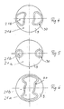
- the new axial seal can be made by punching out a two-layer material, the first layer contains the high-strength thermoplastic and optionally the fiber insert and the second layer contains the rubber-elastic material.
- the axial seal can also be assembled from a separately produced locking ring and sealing ring by gluing them together in pairs or vulcanizing them together.
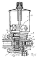
- Fig. 1 shows a vane cell pump provided as a power steering pump in a combined, horizontal and vertical longitudinal section. Below the machine axis 1-1, the cutting plane runs horizontally with the exception of the pump outlet 2, and above the axis 1-1, the cutting plane is vertical.
- a cup-shaped pump housing main part 3 and a pump housing cover 4 are provided, which are screwed together in a sealed manner and enclose a cavity 3a in which a pump package 5 is accommodated.
- the pump package 5 contains a rotor 6 with vanes 7 guided in slots, a lifting ring 8, a pressure plate 9 and a wear plate 10, which are held together by pins 11, with a fixing to the pump housing cover 4 optionally taking place.
- the rotor 6 is driven by a shaft 12.
- a pressure chamber 13 which continues in the direction of the axis 1 into a valve chamber for receiving a valve 14 which is designed as a combined flow control and pressure limiting valve.
- a Valve spring 15 urges valve 14 against the back of pressure plate 9 with a force of approximately 46 Newtons.
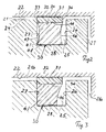
- a vertical or slightly inclined feed channel 17 leads from a storage container 16 into a knee-shaped curved suction channel 18, which leads to an opening 20 in the pressure plate 9. Since the thickness of the pump package 5 in the axial direction is necessarily a small amount less than the dimension of the interior 3a of the pump housing 3, there is a gap 21 between the bottom surface 22 of the pump housing 3 and the rear side 24 of the pressure plate 9. This gap 21 has one axial width of 0.1 to 0.4 mm and connects the pressure area 13 with the suction area 18, 20 and must therefore be sealed. For this purpose, an axial seal 30 surrounding the suction channels 18, 20 is provided, which is accommodated in an annular groove 25 of the pressure plate 9. The annular groove could just as easily be provided in the pump housing 3.
- the gap 21 has a pressure-side area 21a and a suction-side area 21b, which are sealed off from one another by means of the seal 30. Accordingly, there is a pressure-side groove flank 26 and a suction-side flank 27 which are connected to one another via the groove bottom 28.
- the axial seal 30 consists of a locking ring 31 and a sealing ring 41, which are integrally or integrally connected to one another.
- a pressure surface 32 or a connecting surface 34 of the locking ring each run parallel to the boundary surfaces 22, 24 of the gap 21 and side surfaces 36 and 37 of the locking ring 31 run parallel to the groove flanks 26, 27.
- the boundary surfaces of the sealing ring 41 are side surfaces 46, 47 or connecting surface 44 and pressure surface 48 have been designated.
- the thickness of the locking ring 31 is less than that of the sealing ring 41, while the dimension in Direction of the gap are approximately the same or that of the sealing ring is a little less.
- the minimum thickness of the locking ring 31 depends on the width of the gap 21, which must be covered well, with a certain projection over the surface 27. With a sealing gap width of approximately 0.4 mm, the locking ring has a thickness of approximately 1 mm. Locking ring and sealing ring taken together have a thickness which is slightly greater than the depth of the groove 25 and the width of the gap 21, so that in the installed state there is a compression of 20 to 30% of the sealing ring 41. With a width of the sealing ring 41 of 1.8 mm and a height of 2 mm, a contact force of approximately 380 Newtons results, with which the surface 32 of the locking ring 31 rests on the surface 22 of the pump housing.
- the hydraulic pressure penetrates into the groove 25 via gaps and urges the sealing ring 41 against the groove surface 27, which lies on the lower pressure side of the gap 21.
- the level of pressure can fluctuate greatly during operation.
- the deformability of the sealing ring 41 leads to a pressure effect similar to that of a liquid, i.e. H. the locking ring 31 is pressed against the surface 22 with a force corresponding to the size of the surface 34.
- the surface 22 has the usual processing roughness, so that - in order to achieve a sealing effect - the locking ring 31 on its surface 32 must show a certain degree of flexibility in order to envelop grooves and elevations in the surface 22.
- the flexibility of the locking ring 31 must not be so great that it is extruded through the gap 21.
- the locking ring 31 must have a core strength which allows it to withstand the considerable hydraulic pressures, while the surface must be sufficiently soft to adapt to the roughness of machine components.
- Thermoplastic which can be selected with the necessary properties, are suitable as the material of the locking ring.
- polytetrafluoroethylene is suitable, its core strength through inserted fibers.
- glass fibers can be increased so that the axial seal according to the invention withstands considerable pressures of, for example, 240 bar and above.
- Pure PTFE is known to deform permanently after a certain load, which is referred to as creep or cold flow. This property is not undesirable here because the surface of the locking ring can adapt to the unevenness of the metallic counter surfaces.
- PTFE is also easily vulcanizable with rubber materials, so that it can be expected that the sealing ring will not detach from the locking ring during operation despite shear stress.
- PTFE can also be filled with other materials such as carbon, graphite, molybdenum sulfide or bronze to increase the resistance to cold flow.
- Ethylene tetrafluoroethylene copolymer can also be used as a material for the locking ring, especially since this material is easy to process.
- Polyterephthalate is also well suited for the intended purpose, since it can be easily vulcanized with the sealing ring.
- polyamides with or without a glass fiber insert are also suitable for the intended purpose, in particular of quality level PA 6.6, since the tough, hard material structure means that hardly any cold flow can be expected under the pressures to be expected and that the sealing ring also has good vulcanizability.
- the first layer of which is the thermoplastic and, if appropriate, the Contains fiber insert and the second layer consists of rubber-elastic material.
- the desired outline shapes are punched out of this two-layer material, a punched out cross-sectional shape with pillow-shaped flanks resulting from the resilient, rubber-elastic material, as shown in FIG. 2.
- the axial seal from separately produced locking rings and sealing rings which are glued or vulcanized to one another along their connecting surface 34 or 44 or - if the requirements are less - are glued.
- Other thermoplastics can also be considered for the locking ring, which will be selected depending on the other requirements at the place of use (temperature resistance, chemical resistance, mechanical abrasion resistance).
Landscapes
- Engineering & Computer Science (AREA)
- Mechanical Engineering (AREA)
- General Engineering & Computer Science (AREA)
- Sealing Devices (AREA)
- Mechanical Sealing (AREA)
- Details And Applications Of Rotary Liquid Pumps (AREA)
- Gasket Seals (AREA)
Applications Claiming Priority (2)
| Application Number | Priority Date | Filing Date | Title |
|---|---|---|---|
| DE3925269 | 1989-07-31 | ||
| DE3925269A DE3925269A1 (de) | 1989-07-31 | 1989-07-31 | Axialdichtung |
Publications (3)
| Publication Number | Publication Date |
|---|---|
| EP0415089A2 true EP0415089A2 (fr) | 1991-03-06 |
| EP0415089A3 EP0415089A3 (en) | 1992-01-15 |
| EP0415089B1 EP0415089B1 (fr) | 1994-06-01 |
Family
ID=6386193
Family Applications (1)
| Application Number | Title | Priority Date | Filing Date |
|---|---|---|---|
| EP90114439A Expired - Lifetime EP0415089B1 (fr) | 1989-07-31 | 1990-07-27 | Joint d'étanchéité axial |
Country Status (3)
| Country | Link |
|---|---|
| EP (1) | EP0415089B1 (fr) |
| AT (1) | ATE106501T1 (fr) |
| DE (2) | DE3925269A1 (fr) |
Cited By (4)
| Publication number | Priority date | Publication date | Assignee | Title |
|---|---|---|---|---|
| EP0540067A2 (fr) * | 1991-08-23 | 1993-05-05 | Van Doorne's Transmissie B.V. | Pompe rotative |
| DE4326627B4 (de) * | 1993-08-07 | 2004-10-07 | Zf Friedrichshafen Ag | Flügelzellenpumpe |
| EP3081741A2 (fr) | 2015-04-17 | 2016-10-19 | Schwäbische Hüttenwerke Automotive GmbH | Pompe |
| DE102015017078A1 (de) | 2015-04-17 | 2016-10-20 | Schwäbische Hüttenwerke Automotive GmbH | Pumpe |
Families Citing this family (1)
| Publication number | Priority date | Publication date | Assignee | Title |
|---|---|---|---|---|
| DE102005014297A1 (de) | 2005-03-24 | 2006-10-05 | Endress + Hauser Gmbh + Co. Kg | Gehäuse für ein elektronisches Gerät und Dichtring für ein Gehäuse |
Citations (5)
| Publication number | Priority date | Publication date | Assignee | Title |
|---|---|---|---|---|
| US4309158A (en) * | 1978-11-03 | 1982-01-05 | Robert Bosch Gmbh | Gear positive displacement machine with U-shaped supporting element for sealing member |
| GB2086480A (en) * | 1980-10-25 | 1982-05-12 | Plessey Co Ltd | A rotary positive-displacement pump |
| DE3445686A1 (de) * | 1984-06-29 | 1986-01-09 | Commercial Shearing, Inc., Youngstown, Ohio | Hydraulikdruckstroemungsmitteldichtung |
| GB2186641A (en) * | 1986-02-18 | 1987-08-19 | Kugler Fonderie Robinetterie | A seal |
| EP0293585A1 (fr) * | 1987-05-30 | 1988-12-07 | Robert Bosch Gmbh | Machine réversible à engrenages (pompe ou moteur) |
-
1989
- 1989-07-31 DE DE3925269A patent/DE3925269A1/de not_active Withdrawn
-
1990
- 1990-07-27 DE DE59005901T patent/DE59005901D1/de not_active Expired - Fee Related
- 1990-07-27 EP EP90114439A patent/EP0415089B1/fr not_active Expired - Lifetime
- 1990-07-27 AT AT90114439T patent/ATE106501T1/de not_active IP Right Cessation
Patent Citations (5)
| Publication number | Priority date | Publication date | Assignee | Title |
|---|---|---|---|---|
| US4309158A (en) * | 1978-11-03 | 1982-01-05 | Robert Bosch Gmbh | Gear positive displacement machine with U-shaped supporting element for sealing member |
| GB2086480A (en) * | 1980-10-25 | 1982-05-12 | Plessey Co Ltd | A rotary positive-displacement pump |
| DE3445686A1 (de) * | 1984-06-29 | 1986-01-09 | Commercial Shearing, Inc., Youngstown, Ohio | Hydraulikdruckstroemungsmitteldichtung |
| GB2186641A (en) * | 1986-02-18 | 1987-08-19 | Kugler Fonderie Robinetterie | A seal |
| EP0293585A1 (fr) * | 1987-05-30 | 1988-12-07 | Robert Bosch Gmbh | Machine réversible à engrenages (pompe ou moteur) |
Cited By (19)
| Publication number | Priority date | Publication date | Assignee | Title |
|---|---|---|---|---|
| EP0540067A2 (fr) * | 1991-08-23 | 1993-05-05 | Van Doorne's Transmissie B.V. | Pompe rotative |
| EP0540067A3 (en) * | 1991-08-23 | 1993-05-12 | Van Doorne's Transmissie B.V. | Rotary pump |
| US5308287A (en) * | 1991-08-23 | 1994-05-03 | Van Doorne's Transmissie B.V. | Rotary pump |
| DE4326627B4 (de) * | 1993-08-07 | 2004-10-07 | Zf Friedrichshafen Ag | Flügelzellenpumpe |
| EP3081741A2 (fr) | 2015-04-17 | 2016-10-19 | Schwäbische Hüttenwerke Automotive GmbH | Pompe |
| DE102015017078A1 (de) | 2015-04-17 | 2016-10-20 | Schwäbische Hüttenwerke Automotive GmbH | Pumpe |
| DE102015105933A1 (de) | 2015-04-17 | 2016-10-20 | Schwäbische Hüttenwerke Automotive GmbH | Pumpe |
| CN106050647A (zh) * | 2015-04-17 | 2016-10-26 | 施瓦本冶金工程汽车有限公司 | 泵 |
| DE102015105933B4 (de) | 2015-04-17 | 2018-04-26 | Schwäbische Hüttenwerke Automotive GmbH | Pumpe |
| US10082139B2 (en) | 2015-04-17 | 2018-09-25 | Schwäbische Hüttenwerke Automotive GmbH | Pump comprising a spring |
| EP3521560A2 (fr) | 2015-04-17 | 2019-08-07 | Schwäbische Hüttenwerke Automotive GmbH | Pompe |
| DE102015017078B4 (de) | 2015-04-17 | 2019-10-24 | Schwäbische Hüttenwerke Automotive GmbH | Pumpe |
| EP3617447A2 (fr) | 2015-04-17 | 2020-03-04 | Schwäbische Hüttenwerke Automotive GmbH | Pompe |
| US11143181B2 (en) | 2015-04-17 | 2021-10-12 | Schwäbische Hüttenwerke Automotive GmbH | Pump comprising a spring |
| DE202016009177U1 (de) | 2015-04-17 | 2023-06-14 | Schwäbische Hüttenwerke Automotive GmbH | Pumpeneinsatz für eine Pumpe |
| DE202016009179U1 (de) | 2015-04-17 | 2023-06-26 | Schwäbische Hüttenwerke Automotive GmbH | Pumpeneinsatz für eine Pumpe |
| DE202016009178U1 (de) | 2015-04-17 | 2023-06-26 | Schwäbische Hüttenwerke Automotive GmbH | Pumpe |
| EP4234883A1 (fr) | 2015-04-17 | 2023-08-30 | Schwäbische Hüttenwerke Automotive GmbH | Pompe avec élément de fixation |
| EP4234931A2 (fr) | 2015-04-17 | 2023-08-30 | Schwäbische Hüttenwerke Automotive GmbH | Pompe |
Also Published As
| Publication number | Publication date |
|---|---|
| EP0415089B1 (fr) | 1994-06-01 |
| DE59005901D1 (de) | 1994-07-07 |
| EP0415089A3 (en) | 1992-01-15 |
| ATE106501T1 (de) | 1994-06-15 |
| DE3925269A1 (de) | 1991-02-07 |
Similar Documents
| Publication | Publication Date | Title |
|---|---|---|
| DE112007003017B4 (de) | Abdichtvorrichtung und Verfahren zum Herstellen dieser Vorrichtung | |
| DE2661104C2 (fr) | ||
| EP1071896B1 (fr) | Element d'etancheite destine a un systeme d'etancheite a anneau de glissement | |
| EP0615085B2 (fr) | Méthode de fabrication d'un joint d'étanchéité à lèvres | |
| WO2011054580A1 (fr) | Douille pour une unité d'entraînement et unité d'entraînement | |
| DE102012108566A1 (de) | Fluidische Steckereinheit und Verbindungseinrichtung für Flüssigkeit führende Komponenten, insbesondere für die Hochleistungsflüssigkeitschromatographie | |
| EP1738078A2 (fr) | Stator pour pompe a vis sans fin excentrique ou moteur a vis sans fin excentrique selon le principe de moineau | |
| DE202005002471U1 (de) | Membranpumpe | |
| EP0415089B1 (fr) | Joint d'étanchéité axial | |
| EP3978751A1 (fr) | Membrane composite pour pompes à membrane | |
| EP2815129A1 (fr) | Système d'étanchéité et pompe équipée d'un système d'étanchéité | |
| DE102013104069B4 (de) | Kreiselpumpe und Anordnung zur saugseitigen Radialspaltabdichtung | |
| WO2007031472A1 (fr) | Pompe a piston | |
| DE102015210004A1 (de) | Zahnradmaschine mit belastungsminderndem Druckfeld an den Lagerkörpern | |
| EP1736668A2 (fr) | Stator pour une pompe à cavité progressive et procédé de fabrication | |
| DE102011014591A1 (de) | Flügelzellenpumpe mit Pumpensteuerring | |
| EP3543568B1 (fr) | Bague d'étanchéité, dispositif formant bague d'étanchéité et utilisation d'un dispositif formant bague d'étanchéité | |
| WO2017076803A1 (fr) | Pompe à vide sèche | |
| DE102009054524A1 (de) | Dichtring für eine Kolbenpumpe | |
| WO1998007986A1 (fr) | Groupe motopompe electrique | |
| DE4326627B4 (de) | Flügelzellenpumpe | |
| DE1653810A1 (de) | Druckbelastete Pumpe | |
| DE19920997B4 (de) | Radialkolbenpumpe | |
| DE19521259C2 (de) | Hydraulische Kolbenmaschine | |
| DE102012213771A1 (de) | Innenzahnradpumpe |
Legal Events
| Date | Code | Title | Description |
|---|---|---|---|
| PUAI | Public reference made under article 153(3) epc to a published international application that has entered the european phase |
Free format text: ORIGINAL CODE: 0009012 |
|
| AK | Designated contracting states |
Kind code of ref document: A2 Designated state(s): AT BE CH DE ES FR GB IT LI NL SE |
|
| PUAL | Search report despatched |
Free format text: ORIGINAL CODE: 0009013 |
|
| AK | Designated contracting states |
Kind code of ref document: A3 Designated state(s): AT BE CH DE ES FR GB IT LI NL SE |
|
| RHK1 | Main classification (correction) |
Ipc: F04C 2/14 |
|
| 17P | Request for examination filed |
Effective date: 19920228 |
|
| RAP1 | Party data changed (applicant data changed or rights of an application transferred) |
Owner name: LUK FAHRZEUG-HYDRAULIK GMBH & CO. KG Owner name: FIRMA CARL FREUDENBERG |
|
| 17Q | First examination report despatched |
Effective date: 19930224 |
|
| GRAA | (expected) grant |
Free format text: ORIGINAL CODE: 0009210 |
|
| AK | Designated contracting states |
Kind code of ref document: B1 Designated state(s): AT BE CH DE ES FR GB IT LI NL SE |
|
| PG25 | Lapsed in a contracting state [announced via postgrant information from national office to epo] |
Ref country code: ES Free format text: THE PATENT HAS BEEN ANNULLED BY A DECISION OF A NATIONAL AUTHORITY Effective date: 19940601 Ref country code: NL Effective date: 19940601 Ref country code: BE Effective date: 19940601 |
|
| REF | Corresponds to: |
Ref document number: 106501 Country of ref document: AT Date of ref document: 19940615 Kind code of ref document: T |
|
| REF | Corresponds to: |
Ref document number: 59005901 Country of ref document: DE Date of ref document: 19940707 |
|
| ITF | It: translation for a ep patent filed |
Owner name: BARZANO' E ZANARDO MILANO S.P.A. |
|
| RAP4 | Party data changed (patent owner data changed or rights of a patent transferred) |
Owner name: LUK FAHRZEUG-HYDRAULIK GMBH & CO. KG Owner name: FIRMA CARL FREUDENBERG |
|
| PG25 | Lapsed in a contracting state [announced via postgrant information from national office to epo] |
Ref country code: AT Effective date: 19940727 |
|
| PG25 | Lapsed in a contracting state [announced via postgrant information from national office to epo] |
Ref country code: LI Effective date: 19940731 Ref country code: CH Effective date: 19940731 |
|
| PG25 | Lapsed in a contracting state [announced via postgrant information from national office to epo] |
Ref country code: SE Effective date: 19940901 |
|
| ET | Fr: translation filed | ||
| GBT | Gb: translation of ep patent filed (gb section 77(6)(a)/1977) |
Effective date: 19940912 |
|
| NLV1 | Nl: lapsed or annulled due to failure to fulfill the requirements of art. 29p and 29m of the patents act | ||
| REG | Reference to a national code |
Ref country code: CH Ref legal event code: PL |
|
| PLBE | No opposition filed within time limit |
Free format text: ORIGINAL CODE: 0009261 |
|
| STAA | Information on the status of an ep patent application or granted ep patent |
Free format text: STATUS: NO OPPOSITION FILED WITHIN TIME LIMIT |
|
| 26N | No opposition filed | ||
| REG | Reference to a national code |
Ref country code: GB Ref legal event code: IF02 |
|
| PGFP | Annual fee paid to national office [announced via postgrant information from national office to epo] |
Ref country code: DE Payment date: 20070820 Year of fee payment: 18 |
|
| PGFP | Annual fee paid to national office [announced via postgrant information from national office to epo] |
Ref country code: GB Payment date: 20070723 Year of fee payment: 18 |
|
| PGFP | Annual fee paid to national office [announced via postgrant information from national office to epo] |
Ref country code: IT Payment date: 20070723 Year of fee payment: 18 |
|
| PGFP | Annual fee paid to national office [announced via postgrant information from national office to epo] |
Ref country code: FR Payment date: 20070718 Year of fee payment: 18 |
|
| GBPC | Gb: european patent ceased through non-payment of renewal fee |
Effective date: 20080727 |
|
| PG25 | Lapsed in a contracting state [announced via postgrant information from national office to epo] |
Ref country code: DE Free format text: LAPSE BECAUSE OF NON-PAYMENT OF DUE FEES Effective date: 20090203 |
|
| REG | Reference to a national code |
Ref country code: FR Ref legal event code: ST Effective date: 20090331 |
|
| PG25 | Lapsed in a contracting state [announced via postgrant information from national office to epo] |
Ref country code: GB Free format text: LAPSE BECAUSE OF NON-PAYMENT OF DUE FEES Effective date: 20080727 |
|
| PG25 | Lapsed in a contracting state [announced via postgrant information from national office to epo] |
Ref country code: IT Free format text: LAPSE BECAUSE OF NON-PAYMENT OF DUE FEES Effective date: 20080727 Ref country code: FR Free format text: LAPSE BECAUSE OF NON-PAYMENT OF DUE FEES Effective date: 20080731 |