EP0414313A1 - Ecran de projection par transparence et système de projection par transparence muni d'un tel écran - Google Patents
Ecran de projection par transparence et système de projection par transparence muni d'un tel écran Download PDFInfo
- Publication number
- EP0414313A1 EP0414313A1 EP90202226A EP90202226A EP0414313A1 EP 0414313 A1 EP0414313 A1 EP 0414313A1 EP 90202226 A EP90202226 A EP 90202226A EP 90202226 A EP90202226 A EP 90202226A EP 0414313 A1 EP0414313 A1 EP 0414313A1
- Authority
- EP
- European Patent Office
- Prior art keywords
- light
- rear projection
- spreading elements
- screen
- projection screen
- Prior art date
- Legal status (The legal status is an assumption and is not a legal conclusion. Google has not performed a legal analysis and makes no representation as to the accuracy of the status listed.)
- Granted
Links
Images


Classifications
-
- G—PHYSICS
- G03—PHOTOGRAPHY; CINEMATOGRAPHY; ANALOGOUS TECHNIQUES USING WAVES OTHER THAN OPTICAL WAVES; ELECTROGRAPHY; HOLOGRAPHY
- G03B—APPARATUS OR ARRANGEMENTS FOR TAKING PHOTOGRAPHS OR FOR PROJECTING OR VIEWING THEM; APPARATUS OR ARRANGEMENTS EMPLOYING ANALOGOUS TECHNIQUES USING WAVES OTHER THAN OPTICAL WAVES; ACCESSORIES THEREFOR
- G03B21/00—Projectors or projection-type viewers; Accessories therefor
- G03B21/54—Accessories
- G03B21/56—Projection screens
- G03B21/60—Projection screens characterised by the nature of the surface
- G03B21/62—Translucent screens
- G03B21/625—Lenticular translucent screens
-
- G—PHYSICS
- G03—PHOTOGRAPHY; CINEMATOGRAPHY; ANALOGOUS TECHNIQUES USING WAVES OTHER THAN OPTICAL WAVES; ELECTROGRAPHY; HOLOGRAPHY
- G03B—APPARATUS OR ARRANGEMENTS FOR TAKING PHOTOGRAPHS OR FOR PROJECTING OR VIEWING THEM; APPARATUS OR ARRANGEMENTS EMPLOYING ANALOGOUS TECHNIQUES USING WAVES OTHER THAN OPTICAL WAVES; ACCESSORIES THEREFOR
- G03B21/00—Projectors or projection-type viewers; Accessories therefor
- G03B21/54—Accessories
- G03B21/56—Projection screens
- G03B21/60—Projection screens characterised by the nature of the surface
Definitions
- the invention relates to a rear projection screen having a front and a rear side for displaying at the front side of the screen a picture supplied by a plurality of primary picture sources arranged at the rear side of the screen, said screen comprising a translucent plate whose front side is provided with a multitude of parallel-arranged first light-spreading elements extending in one direction across the plate for spreading light in a plane perpendicular to the said direction, said elements having steep edges for obtaining total internal reflection and having a top with a portion for transmission and refraction.
- the invention also relates to a rear projection system comprising such a rear projection screen.
- Rear projection screens are used in rear projection systems for video and cinematographic pictures and in various other types of display systems such as radar screens, airplane and ship simulators and microfilm readers.
- a picture generated in a primary picture source is imaged by a system of projection lenses on the rear side of the rear projection screen.
- the projection screen spreads the incident light in the audience space at the front side of the screen.
- Current projection systems for displaying color television or video programs comprise three primary picture sources for the primary colors red, green and blue which are projected on the screen by separate projection lens systems.
- the light intensity of each primary picture source is maximum on the optical axis of the relevant picture source and the associated projection lens system. Since the three picture sources are arranged besides or above to each other, the said axes extend at an angle at the location of the projection screen so that without any further measures the viewer observes a color shift which depends on his position in the audience space.
- EP-A 0,148,529 describes a rear projection screen in which this color shift in the horizontal direction is reduced to a minimum. This is achieved by providing vertically extending light-spreading elements at the front side of the screen whose ratio between height and width is at least 1 : 1 and whose top has a width which is at most half the width at the base, this top having a specially shaped indentation.
- the "height" of the element is understood to mean the maximum relief perpendicular to the plane of the screen.
- Light-absorbing material may be provided in the deep grooves between the elements so that reflection of ambient light is inhibited by the screen and the contrast in the displayed picture is enhanced.
- the light from the primary picture source incident on the rear side of the screen is guided to the tops of the profile due to total internal reflection on the steep edges so that there is a high transmission for this light. Due to the combination of steep edges and curved flatter tops a broad angular distribution in the horizontal direction is achieved. As a result of the repeated reflections on the edges the spread of light at the front side is largely independent of the position of the primary picture source.
- the vertically extending elements spread the light entering via the rear side in a horizontal direction in an area of approximately 85° to the left and right.
- the light-spreading elements do not have any noticeable effect so that other measures are to be taken for spreading light in that direction.
- roughening the rear side of the plate or providing the plate with a light-scattering material as proposed in EP-A 0,148,529.
- the cutting tool should substantially not be subject to wear.
- a change in shape is unacceptable because it affects the light spread which can clearly be observed by the viewer.
- it is impossible to replace a worn cutting tool by a new one because then a small but clearly visible change in light spread occurs.
- only diamond is suitable as a material for the cutting tool.
- a screen has to be accepted whose elements provided at the front side have a color spread which is less than optimum so that some color shift remains.
- One of the objects of the invention is to provide a rear projection screen which, in spite of the said technical limitations, may have a large surface area and exhibits substantially no noticeable color shift.
- the projection screen according to the invention is characterized in that the rear side of the plate is provided with parallel-arranged second light-spreading elements which extend mainly in the said direction for spreading the light already upon its entrance into the plate in a plane perpendicular to said direction. It has been found that the use of the second light-spreading elements at the rear side of the screen is an adequate remedy against the color shift which results from the less than optimum shape of the first light-spreading elements.
- An embodiment of the projection screen according to the invention is further characterized in that the pitch of the second light-spreading elements is considerably smaller than the pitch of the first light-spreading elements.
- the projection screen is preferably further characterized in that the pitch of the second light-spreading elements is at most approximately 1/5 of the pitch of the first light-spreading elements. Since the second light-spreading elements are much smaller than the light-spreading elements at the front side, there is no noticeable Moiré interference. As a result, the light-spreading elements at the rear side need not register with respect to the elements at the front side, i.e. it is not necessary to maintain a fixed relationship between the elements on both sides of the plate. A ratio of approximately 1 : 5.5 between the pitch at the front side and at the rear side of the screen is acceptable as a compromise between reducing the Moiré effect and the manufacturing requirements.
- the projection screen according to the invention is preferably characterized in that the second light-spreading elements extend in a direction at an angle of at most 30° to the direction in which the first light-spreading elements extend.
- the second light-spreading elements By arranging the light-spreading elements at the rear side in such a way that they are not parallel to those at the front side, the second light-spreading elements contribute to the spreading of light in the vertical direction.
- the angle between the first and second light-spreading elements should, however, become not too large because then the effect envisaged by the invention is lost and color errors may be introduced.
- An embodiment of the projection screen according to the invention is characterized in that the second light-spreading elements refract light which is substantially perpendicularly incident on the rear side of the screen through an angle which is at most approximately 20 o . It has been found that this angle is sufficient to eliminate the noticeable color shift and that the elements at the rear side only show a small relief which is an advantage for the manufacturing possibilities of the plate.
- the rear projection screen according to the invention may also be characterized in that the maximum angle between the surface of the second light-spreading elements and the plane of the plate has a value of between approximately 20 o and approximately 40 o .
- the conventional materials for a projection screen such as polymethyl methacrylate (PMMA) have a refractive index n of approximately 1.5.
- the said geometrical angles of approximately 20 o and approximately 40 o result approximately in the above-mentioned deflection at this value of n.
- An embodiment of the rear projection screen according to the invention is characterized in that the second light-spreading elements are convex elements. Another embodiment is, however, characterized in that the second light-spreading elements are concave elements.
- a further embodiment of the rear projection screen according to the invention is characterized in that a plurality of the second light-spreading elements is convex and a plurality is concave. In this respect this embodiment may be further characterized in that the convex and concave second light-spreading elements alternate with one another.
- a preferred embodiment of the rear projection screen according to the invention is characterized in that the cross-sections of the second light-spreading elements approximately have the shape of a segment of a circle.
- the rear projection screen according to the invention may be further characterized in that a segment of a circle forms an arc of approximately 60 o . This shape can be manufactured in a relatively simple way without any technical problems.
- the rear projection screen according to the invention is further characterized in that a diffusor is arranged in the plate.
- a diffusor is arranged in the plate.
- the rear projection screen according to the invention may be further characterized in that the rear side of the plate is anti-reflective. This reduces both loss of light coming from the primary picture source due to reflection at the rear side of the plate and reflection of ambient light entering through the front side of the plate.
- the rear side may be made anti-reflective by providing a conventional cladding consisting of one or more layers thereon or by providing it with a microrelief structure as described in the magazine "Optica Acta" vol. 29, no. 7, pp. 993-1009 (1982).
- the invention also relates to a rear projection system comprising a plurality of primary picture sources, a plurality of lens systems and a rear projection screen as described hereinbefore for projecting the picture generated by the primary picture source.
- Fig. 1 shows diagrammatically a horizontal cross-section sof a rear projection system for displaying a color television or video program, which system comprises a known rear projection screen.
- the reference numerals 11, 12 and 13 show three primary picture sources, for example cathode ray tubes which generate the red, green or blue components of a color video picture on their respective display windows 14, 15 and 16.
- the picture components thus formed are projected on the projection screen 30 by the projection lens systems 21, 22 and 23 which are shown diagrammatically as single lenses.
- the screen shown comprises two plates.
- the rear plate 31 has a Fresnel structure so that the pupils of the projection lens systems are imaged in the audience space.
- the front plate 40 has elements 41 at its front side which spread the light in the plane of the drawing, i.e. the horizontal plane. These elements extend throughout the height of the screen, transversely to the plane of the drawing. The elements whose top has an indentation have very good properties with regard to the spreading of light in the horizontal direction and the color shift in that plane.
- Such a structure at which the height D is at least equal to half the width B is described in the previously mentioned EP-A 0,148,529.
- the spreading of the light perpendicular to the plane of the drawing, i.e. in the vertical direction results, in the screen shown, from a large number of transparent grains 42 incorporated for that purpose in the front plate whose refractive index deviates from the refractive index of the plate material.
- this relief structure with a small to very small pitch of at most approximately 1 mm meets with technical difficulties. Due to these technical problems it is preferable to provide the front side of the screen with a relief as shown in Fig. 2. Since this profile has less good properties with regard to color shift, the screen is provided at its rear side with a simple relief having a very small pitch.
- the front side of the plate 50 is provided with light- spreading elements 51 which have two steep edges 52 and 53 and a top portion comprising two segments 54 and 55 of a circle located against each other.
- a deep groove 56 has been left between the edges of two adjacent elements. The bottom of this groove 56 is as narrow as possible and preferably the edges 52 and 53 of adjacent elements 50 are directly contiguous.
- the dimensions of the relief profile are, for example, as follows.
- the angle at which the edges extend to the normal of the plate is approximately 15 o so that the angle enclosed by the edges is approximately 30 o .
- the width B of the elements is approximately 520 ⁇ m and the width b is approximately 20 ⁇ m so that the pitch is 540 ⁇ m.
- the height h2 of an element as far as the deepest point of the indentation is, for example 245 ⁇ m and the total height of the element h2 is 340 ⁇ m. If desired, these values can be reduced by 50% without detracting from the functions.
- the rear side of the plate is provided with second light-spreading elements 61 having approximately the shape of a segment of a circle.
- the angle ⁇ between the normal on the surface of an element and the normal on the plane of the plate is approximately 30 o and hence the angle ⁇ which is enclosed between the surfaces of two adjacent elements is approximately 120 o .
- the width p of an element is, for example 100 ⁇ m. If necessary, this width can be reduced by 50% and thus be approximately 50 ⁇ m. It is not required for the second light-spreading elements 61 to have a fixed position with respect to the first light-spreading elements 51 or to be precisely parallel aligned thereto. To obtain spreading of light in the vertical direction, a bulk diffusor is incorporated in the plate material, for example in the form of transparent grains 57 having a deviating refractive index.
- Fig. 3 shows another embodiment of the plate.
- the light-spreading elements at the outer side were convex
- the light-spreading elements 62 at the outer side are now concave.
- the values of the angles ⁇ and ⁇ and of the width p may be equal to those of the plate shown in Fig. 2.
- Fig. 4 shows again in a cross-section a third embodiment of the plate.
- the light-spreading elements 63 are alternately convex and concave and they blend with each other.
- the widths p1 and p2 of the convex and concave elements may be equal or unequal.
- the rear side of the screen is made, for example anti-reflective. This can be realised, for example by providing a conventional single-layer or multilayer anti-reflective coating on the rear side, but also by providing the rear side with a fine roughening coated with a layer of constant thickness as described in EP-A-0,131,341. It is also possible to provide the rear side with a microrelief structure which is known as "moth eye structure" and is described, for example in the magazine “Optica Acta", vol. 29, no. 7, pp. 993-1009. This measure can also be used for the screens shown in Figs. 2 and 3.
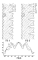
- the embodiment of the screen shown in Fig. 5 comprises light-spreading elements 51 whose edges consist of two segments each, 52a, 52b, 53a and 53b.
- the segments 52a and 53a are located at the base of the light-spreading elements and extend at a relatively large angle to the normal on the plane of the screen.
- the front segments 52b and 53b extend at a small angle to the normal or are even perpendicular to the screen.
- This shape of light-spreading elements can be combined with any one of the modifications of the structure at the rear side.
- Fig. 6 shows the spreading of light of a screen according to the invention.
- the angle is plotted on the horizontal axis in this Figure and the intensity of the light emerging at the indicated angle from the screen for each of the three primary picture sources is plotted on the vertical axis (in arbitrary units).
- the light intensity is denoted by means of the characters R, G and B for the light coming from the red, the green and the blue picture source, respectively.
- the graph states that the light intensity is approximately equal for each one of the three colors and that none of the three colors is clearly predominant within the angle of approximately ⁇ 50 o .
Landscapes
- Physics & Mathematics (AREA)
- General Physics & Mathematics (AREA)
- Overhead Projectors And Projection Screens (AREA)
- Transforming Electric Information Into Light Information (AREA)
- Video Image Reproduction Devices For Color Tv Systems (AREA)
- Projection Apparatus (AREA)
Applications Claiming Priority (2)
| Application Number | Priority Date | Filing Date | Title |
|---|---|---|---|
| NL8902112A NL8902112A (nl) | 1989-08-22 | 1989-08-22 | Doorzichtprojektiescherm en doorzichtprojektiesysteem voorzien van een dergelijk scherm. |
| NL8902112 | 1989-08-22 |
Publications (2)
| Publication Number | Publication Date |
|---|---|
| EP0414313A1 true EP0414313A1 (fr) | 1991-02-27 |
| EP0414313B1 EP0414313B1 (fr) | 1995-04-19 |
Family
ID=19855196
Family Applications (1)
| Application Number | Title | Priority Date | Filing Date |
|---|---|---|---|
| EP90202226A Expired - Lifetime EP0414313B1 (fr) | 1989-08-22 | 1990-08-20 | Ecran de projection par transparence et système de projection par transparence muni d'un tel écran |
Country Status (7)
| Country | Link |
|---|---|
| US (1) | US5005945A (fr) |
| EP (1) | EP0414313B1 (fr) |
| JP (1) | JP2993718B2 (fr) |
| KR (1) | KR0166360B1 (fr) |
| DE (1) | DE69018735T2 (fr) |
| DK (1) | DK0414313T3 (fr) |
| NL (1) | NL8902112A (fr) |
Cited By (5)
| Publication number | Priority date | Publication date | Assignee | Title |
|---|---|---|---|---|
| WO2001035128A2 (fr) * | 1999-11-12 | 2001-05-17 | Reflexite Corporation | Films de collimation de lumiere a microstructure optique a sous-longueur d'onde |
| US6356389B1 (en) | 1999-11-12 | 2002-03-12 | Reflexite Corporation | Subwavelength optical microstructure light collimating films |
| WO2004031853A1 (fr) * | 2002-10-07 | 2004-04-15 | Dnp Denmark A/S | Ecran de projection arriere conçu pour s'adapter a un espace libre |
| FR2849932A1 (fr) * | 2003-01-15 | 2004-07-16 | Saint Gobain | Ecran de retroprojection et/ou de projection |
| US8300311B2 (en) | 2009-01-20 | 2012-10-30 | Glasstech Doo | Rear projection system, method for production and application |
Families Citing this family (16)
| Publication number | Priority date | Publication date | Assignee | Title |
|---|---|---|---|---|
| US5617152A (en) * | 1993-06-20 | 1997-04-01 | Unic View Ltd. | Projector system for video and computer generated information |
| US5706062A (en) * | 1993-06-20 | 1998-01-06 | Unic View Ltd. | Projector system including keystone correction |
| US5481385A (en) * | 1993-07-01 | 1996-01-02 | Alliedsignal Inc. | Direct view display device with array of tapered waveguide on viewer side |
| US5521726A (en) * | 1994-08-26 | 1996-05-28 | Alliedsignal Inc. | Polarizer with an array of tapered waveguides |
| US5657408A (en) * | 1994-12-23 | 1997-08-12 | Alliedsignal Inc. | Optical device comprising a plurality of units having at least two geometrically-differentiated tapered optical waveguides therein |
| US5760955A (en) * | 1995-04-06 | 1998-06-02 | Philips Electronics North America Corporation | Rear projection screen with reduced speckle |
| CN1216617A (zh) * | 1996-03-18 | 1999-05-12 | 扫描影像屏幕公司 | 背面投影屏 |
| US6280063B1 (en) | 1997-05-09 | 2001-08-28 | 3M Innovative Properties Company | Brightness enhancement article |
| JPH11102024A (ja) * | 1997-09-29 | 1999-04-13 | Dainippon Printing Co Ltd | 透過型スクリーン |
| US6600599B2 (en) | 1998-06-09 | 2003-07-29 | Avery Dennison Corporation | Rear projection screens and light filters with conformable coatings and methods of making the same |
| JP2001054131A (ja) * | 1999-05-31 | 2001-02-23 | Olympus Optical Co Ltd | カラー画像表示システム |
| US6417966B1 (en) * | 1999-07-07 | 2002-07-09 | 3M Innovative Properties Company | Rear projection screen using internal reflection |
| JP2004271777A (ja) * | 2003-03-07 | 2004-09-30 | Dainippon Printing Co Ltd | 光学部材 |
| WO2004085067A1 (fr) * | 2003-03-25 | 2004-10-07 | Dai Nippon Printing Co. Ltd. | Feuille de diffusion, ecran de transmission l'utilisant, moule pour feuille de diffusion et procede de production de feuilles de diffusion |
| CN101191845A (zh) * | 2006-12-01 | 2008-06-04 | 鸿富锦精密工业(深圳)有限公司 | 光学板 |
| JP5616009B2 (ja) * | 2008-09-22 | 2014-10-29 | アズビル株式会社 | 反射型光電センサおよび物体検出方法 |
Citations (2)
| Publication number | Priority date | Publication date | Assignee | Title |
|---|---|---|---|---|
| EP0148529A2 (fr) * | 1983-12-30 | 1985-07-17 | North American Philips Corporation | Ecran de projection par transparence |
| EP0281690A1 (fr) * | 1987-01-21 | 1988-09-14 | Koninklijke Philips Electronics N.V. | Ecran de projection par l'arrière et système de projection pourvu d'un tel système |
Family Cites Families (7)
| Publication number | Priority date | Publication date | Assignee | Title |
|---|---|---|---|---|
| US4418986A (en) * | 1981-04-07 | 1983-12-06 | Mitsubishi Rayon Co., Ltd. | Rear projection screen |
| US4469402A (en) * | 1981-06-15 | 1984-09-04 | Mitsubishi Rayon Co., Ltd. | Rear projection screen |
| DK156188C (da) * | 1983-05-10 | 1989-11-27 | Scan Screen Production A S | Transparent baglysprojektionsskaerm |
| DK151320C (da) * | 1983-10-12 | 1988-05-09 | Scan Screen | Transparent baglysprojektionsskaerm |
| US4679900A (en) * | 1986-06-05 | 1987-07-14 | North American Philips Corporation | Bulk diffuser for a projection television screen |
| US4730897A (en) * | 1987-04-21 | 1988-03-15 | North American Philips Corporation | Projection screen having high resolution and good mechanical stability |
| US4773731A (en) * | 1987-08-28 | 1988-09-27 | North American Philips Corp. | One-piece projection screen |
-
1989
- 1989-08-22 NL NL8902112A patent/NL8902112A/nl not_active Application Discontinuation
-
1990
- 1990-07-19 US US07/556,939 patent/US5005945A/en not_active Expired - Lifetime
- 1990-08-20 EP EP90202226A patent/EP0414313B1/fr not_active Expired - Lifetime
- 1990-08-20 KR KR1019900012782A patent/KR0166360B1/ko not_active IP Right Cessation
- 1990-08-20 DE DE69018735T patent/DE69018735T2/de not_active Expired - Fee Related
- 1990-08-20 DK DK90202226.8T patent/DK0414313T3/da active
- 1990-08-21 JP JP2218256A patent/JP2993718B2/ja not_active Expired - Fee Related
Patent Citations (2)
| Publication number | Priority date | Publication date | Assignee | Title |
|---|---|---|---|---|
| EP0148529A2 (fr) * | 1983-12-30 | 1985-07-17 | North American Philips Corporation | Ecran de projection par transparence |
| EP0281690A1 (fr) * | 1987-01-21 | 1988-09-14 | Koninklijke Philips Electronics N.V. | Ecran de projection par l'arrière et système de projection pourvu d'un tel système |
Cited By (11)
| Publication number | Priority date | Publication date | Assignee | Title |
|---|---|---|---|---|
| WO2001035128A2 (fr) * | 1999-11-12 | 2001-05-17 | Reflexite Corporation | Films de collimation de lumiere a microstructure optique a sous-longueur d'onde |
| US6356389B1 (en) | 1999-11-12 | 2002-03-12 | Reflexite Corporation | Subwavelength optical microstructure light collimating films |
| WO2001035128A3 (fr) * | 1999-11-12 | 2002-05-02 | Reflexite Corp | Films de collimation de lumiere a microstructure optique a sous-longueur d'onde |
| US6570710B1 (en) | 1999-11-12 | 2003-05-27 | Reflexite Corporation | Subwavelength optical microstructure light collimating films |
| US6891677B2 (en) * | 1999-11-12 | 2005-05-10 | Reflexite Corporation | Subwavelength optical microstructure light-redirecting films |
| WO2004031853A1 (fr) * | 2002-10-07 | 2004-04-15 | Dnp Denmark A/S | Ecran de projection arriere conçu pour s'adapter a un espace libre |
| FR2849932A1 (fr) * | 2003-01-15 | 2004-07-16 | Saint Gobain | Ecran de retroprojection et/ou de projection |
| WO2004072722A2 (fr) * | 2003-01-15 | 2004-08-26 | Saint-Gobain Glass France | ECRAN DE RETROPROJECTION et/ou de PROJECTION |
| WO2004072722A3 (fr) * | 2003-01-15 | 2005-03-24 | Saint Gobain | ECRAN DE RETROPROJECTION et/ou de PROJECTION |
| US7609443B2 (en) | 2003-01-15 | 2009-10-27 | Saint-Gobain Glass France | Projection and/or rear projection screen |
| US8300311B2 (en) | 2009-01-20 | 2012-10-30 | Glasstech Doo | Rear projection system, method for production and application |
Also Published As
| Publication number | Publication date |
|---|---|
| DE69018735D1 (de) | 1995-05-24 |
| DE69018735T2 (de) | 1996-01-04 |
| NL8902112A (nl) | 1991-03-18 |
| DK0414313T3 (da) | 1995-07-24 |
| KR910005089A (ko) | 1991-03-30 |
| JP2993718B2 (ja) | 1999-12-27 |
| KR0166360B1 (ko) | 1999-05-01 |
| JPH0384532A (ja) | 1991-04-10 |
| EP0414313B1 (fr) | 1995-04-19 |
| US5005945A (en) | 1991-04-09 |
Similar Documents
| Publication | Publication Date | Title |
|---|---|---|
| EP0414313B1 (fr) | Ecran de projection par transparence et système de projection par transparence muni d'un tel écran | |
| US4762393A (en) | Rear projection screen and rear projection system provided with such a screen | |
| EP0148529B1 (fr) | Ecran de projection par transparence | |
| US4767186A (en) | Front projection screen with rear light concentrating lens array | |
| US5400114A (en) | Rear-projection screen and a rear projection image display employing the rear-projection screen | |
| EP0260758B1 (fr) | Ecran à uniformité avancée de luminance pour projection par transparence | |
| US4374609A (en) | Image projection screen with decreased color shift as a function of viewing angle, and method of manufacture | |
| EP1006399A2 (fr) | Feuille lentille de Fresnel | |
| EP0604325A2 (fr) | Ecran pour dispositif d'affichage par projection | |
| EP0511721A2 (fr) | Ecran de projection par réflection avec un réseau de lentilles pour concentrer la lumière réfléchie | |
| US4919515A (en) | Screen for a rear projection type television set | |
| US4387959A (en) | Rear projection screen | |
| EP0874269A1 (fr) | Ecran de rétroprojection | |
| JP2695422B2 (ja) | 透過型スクリーン | |
| CA1214488A (fr) | Appareil d'affichage d'images | |
| US4118114A (en) | Low-glare overhead projector | |
| US5071224A (en) | Lenticular lens for use in back projection type television receiver | |
| JPS63165838A (ja) | 透過型スクリ−ン | |
| JP3342715B2 (ja) | フレネルレンズシート | |
| JPS5969748A (ja) | 透過型投影スクリ−ン | |
| JP3182218B2 (ja) | 背面投射型スクリーン | |
| JPH0351154B2 (fr) | ||
| JP2695420B2 (ja) | 透過型スクリーン | |
| JPH0345987A (ja) | 背面投射型表示装置 | |
| JPH10300909A (ja) | レンチキュラーレンズシート |
Legal Events
| Date | Code | Title | Description |
|---|---|---|---|
| PUAI | Public reference made under article 153(3) epc to a published international application that has entered the european phase |
Free format text: ORIGINAL CODE: 0009012 |
|
| AK | Designated contracting states |
Kind code of ref document: A1 Designated state(s): DE DK FR GB IT |
|
| 17P | Request for examination filed |
Effective date: 19910808 |
|
| 17Q | First examination report despatched |
Effective date: 19930413 |
|
| GRAA | (expected) grant |
Free format text: ORIGINAL CODE: 0009210 |
|
| AK | Designated contracting states |
Kind code of ref document: B1 Designated state(s): DE DK FR GB IT |
|
| REF | Corresponds to: |
Ref document number: 69018735 Country of ref document: DE Date of ref document: 19950524 |
|
| ITF | It: translation for a ep patent filed |
Owner name: ING. C. GREGORJ S.P.A. |
|
| ET | Fr: translation filed | ||
| REG | Reference to a national code |
Ref country code: DK Ref legal event code: T3 |
|
| PLBE | No opposition filed within time limit |
Free format text: ORIGINAL CODE: 0009261 |
|
| STAA | Information on the status of an ep patent application or granted ep patent |
Free format text: STATUS: NO OPPOSITION FILED WITHIN TIME LIMIT |
|
| 26N | No opposition filed | ||
| REG | Reference to a national code |
Ref country code: FR Ref legal event code: CD |
|
| PGFP | Annual fee paid to national office [announced via postgrant information from national office to epo] |
Ref country code: DK Payment date: 20010803 Year of fee payment: 12 |
|
| REG | Reference to a national code |
Ref country code: GB Ref legal event code: IF02 |
|
| PG25 | Lapsed in a contracting state [announced via postgrant information from national office to epo] |
Ref country code: DK Free format text: LAPSE BECAUSE OF NON-PAYMENT OF DUE FEES Effective date: 20020930 |
|
| REG | Reference to a national code |
Ref country code: DK Ref legal event code: EBP |
|
| PGFP | Annual fee paid to national office [announced via postgrant information from national office to epo] |
Ref country code: DE Payment date: 20041015 Year of fee payment: 15 |
|
| REG | Reference to a national code |
Ref country code: GB Ref legal event code: 746 Effective date: 20050518 |
|
| REG | Reference to a national code |
Ref country code: FR Ref legal event code: D6 |
|
| PGFP | Annual fee paid to national office [announced via postgrant information from national office to epo] |
Ref country code: FR Payment date: 20050812 Year of fee payment: 16 |
|
| PG25 | Lapsed in a contracting state [announced via postgrant information from national office to epo] |
Ref country code: IT Free format text: LAPSE BECAUSE OF NON-PAYMENT OF DUE FEES;WARNING: LAPSES OF ITALIAN PATENTS WITH EFFECTIVE DATE BEFORE 2007 MAY HAVE OCCURRED AT ANY TIME BEFORE 2007. THE CORRECT EFFECTIVE DATE MAY BE DIFFERENT FROM THE ONE RECORDED. Effective date: 20050820 |
|
| PGFP | Annual fee paid to national office [announced via postgrant information from national office to epo] |
Ref country code: GB Payment date: 20050830 Year of fee payment: 16 |
|
| PG25 | Lapsed in a contracting state [announced via postgrant information from national office to epo] |
Ref country code: DE Free format text: LAPSE BECAUSE OF NON-PAYMENT OF DUE FEES Effective date: 20060301 |
|
| GBPC | Gb: european patent ceased through non-payment of renewal fee |
Effective date: 20060820 |
|
| REG | Reference to a national code |
Ref country code: FR Ref legal event code: ST Effective date: 20070430 |
|
| PG25 | Lapsed in a contracting state [announced via postgrant information from national office to epo] |
Ref country code: GB Free format text: LAPSE BECAUSE OF NON-PAYMENT OF DUE FEES Effective date: 20060820 |
|
| PG25 | Lapsed in a contracting state [announced via postgrant information from national office to epo] |
Ref country code: FR Free format text: LAPSE BECAUSE OF NON-PAYMENT OF DUE FEES Effective date: 20060831 |