EP0414074B1 - Transform coding apparatus - Google Patents
Transform coding apparatus Download PDFInfo
- Publication number
- EP0414074B1 EP0414074B1 EP90115439A EP90115439A EP0414074B1 EP 0414074 B1 EP0414074 B1 EP 0414074B1 EP 90115439 A EP90115439 A EP 90115439A EP 90115439 A EP90115439 A EP 90115439A EP 0414074 B1 EP0414074 B1 EP 0414074B1
- Authority
- EP
- European Patent Office
- Prior art keywords
- transform
- quantization
- threshold value
- frequency components
- coefficients
- Prior art date
- Legal status (The legal status is an assumption and is not a legal conclusion. Google has not performed a legal analysis and makes no representation as to the accuracy of the status listed.)
- Expired - Lifetime
Links
Images


Classifications
-
- H—ELECTRICITY
- H04—ELECTRIC COMMUNICATION TECHNIQUE
- H04N—PICTORIAL COMMUNICATION, e.g. TELEVISION
- H04N19/00—Methods or arrangements for coding, decoding, compressing or decompressing digital video signals
- H04N19/10—Methods or arrangements for coding, decoding, compressing or decompressing digital video signals using adaptive coding
- H04N19/102—Methods or arrangements for coding, decoding, compressing or decompressing digital video signals using adaptive coding characterised by the element, parameter or selection affected or controlled by the adaptive coding
- H04N19/124—Quantisation
-
- H—ELECTRICITY
- H04—ELECTRIC COMMUNICATION TECHNIQUE
- H04N—PICTORIAL COMMUNICATION, e.g. TELEVISION
- H04N19/00—Methods or arrangements for coding, decoding, compressing or decompressing digital video signals
- H04N19/10—Methods or arrangements for coding, decoding, compressing or decompressing digital video signals using adaptive coding
- H04N19/169—Methods or arrangements for coding, decoding, compressing or decompressing digital video signals using adaptive coding characterised by the coding unit, i.e. the structural portion or semantic portion of the video signal being the object or the subject of the adaptive coding
- H04N19/18—Methods or arrangements for coding, decoding, compressing or decompressing digital video signals using adaptive coding characterised by the coding unit, i.e. the structural portion or semantic portion of the video signal being the object or the subject of the adaptive coding the unit being a set of transform coefficients
-
- H—ELECTRICITY
- H04—ELECTRIC COMMUNICATION TECHNIQUE
- H04N—PICTORIAL COMMUNICATION, e.g. TELEVISION
- H04N19/00—Methods or arrangements for coding, decoding, compressing or decompressing digital video signals
- H04N19/10—Methods or arrangements for coding, decoding, compressing or decompressing digital video signals using adaptive coding
- H04N19/102—Methods or arrangements for coding, decoding, compressing or decompressing digital video signals using adaptive coding characterised by the element, parameter or selection affected or controlled by the adaptive coding
- H04N19/124—Quantisation
- H04N19/126—Details of normalisation or weighting functions, e.g. normalisation matrices or variable uniform quantisers
-
- H—ELECTRICITY
- H04—ELECTRIC COMMUNICATION TECHNIQUE
- H04N—PICTORIAL COMMUNICATION, e.g. TELEVISION
- H04N19/00—Methods or arrangements for coding, decoding, compressing or decompressing digital video signals
- H04N19/10—Methods or arrangements for coding, decoding, compressing or decompressing digital video signals using adaptive coding
- H04N19/102—Methods or arrangements for coding, decoding, compressing or decompressing digital video signals using adaptive coding characterised by the element, parameter or selection affected or controlled by the adaptive coding
- H04N19/132—Sampling, masking or truncation of coding units, e.g. adaptive resampling, frame skipping, frame interpolation or high-frequency transform coefficient masking
-
- H—ELECTRICITY
- H04—ELECTRIC COMMUNICATION TECHNIQUE
- H04N—PICTORIAL COMMUNICATION, e.g. TELEVISION
- H04N19/00—Methods or arrangements for coding, decoding, compressing or decompressing digital video signals
- H04N19/10—Methods or arrangements for coding, decoding, compressing or decompressing digital video signals using adaptive coding
- H04N19/134—Methods or arrangements for coding, decoding, compressing or decompressing digital video signals using adaptive coding characterised by the element, parameter or criterion affecting or controlling the adaptive coding
- H04N19/146—Data rate or code amount at the encoder output
- H04N19/152—Data rate or code amount at the encoder output by measuring the fullness of the transmission buffer
-
- H—ELECTRICITY
- H04—ELECTRIC COMMUNICATION TECHNIQUE
- H04N—PICTORIAL COMMUNICATION, e.g. TELEVISION
- H04N19/00—Methods or arrangements for coding, decoding, compressing or decompressing digital video signals
- H04N19/10—Methods or arrangements for coding, decoding, compressing or decompressing digital video signals using adaptive coding
- H04N19/134—Methods or arrangements for coding, decoding, compressing or decompressing digital video signals using adaptive coding characterised by the element, parameter or criterion affecting or controlling the adaptive coding
- H04N19/154—Measured or subjectively estimated visual quality after decoding, e.g. measurement of distortion
-
- H—ELECTRICITY
- H04—ELECTRIC COMMUNICATION TECHNIQUE
- H04N—PICTORIAL COMMUNICATION, e.g. TELEVISION
- H04N19/00—Methods or arrangements for coding, decoding, compressing or decompressing digital video signals
- H04N19/10—Methods or arrangements for coding, decoding, compressing or decompressing digital video signals using adaptive coding
- H04N19/169—Methods or arrangements for coding, decoding, compressing or decompressing digital video signals using adaptive coding characterised by the coding unit, i.e. the structural portion or semantic portion of the video signal being the object or the subject of the adaptive coding
- H04N19/17—Methods or arrangements for coding, decoding, compressing or decompressing digital video signals using adaptive coding characterised by the coding unit, i.e. the structural portion or semantic portion of the video signal being the object or the subject of the adaptive coding the unit being an image region, e.g. an object
- H04N19/176—Methods or arrangements for coding, decoding, compressing or decompressing digital video signals using adaptive coding characterised by the coding unit, i.e. the structural portion or semantic portion of the video signal being the object or the subject of the adaptive coding the unit being an image region, e.g. an object the region being a block, e.g. a macroblock
-
- H—ELECTRICITY
- H04—ELECTRIC COMMUNICATION TECHNIQUE
- H04N—PICTORIAL COMMUNICATION, e.g. TELEVISION
- H04N19/00—Methods or arrangements for coding, decoding, compressing or decompressing digital video signals
- H04N19/10—Methods or arrangements for coding, decoding, compressing or decompressing digital video signals using adaptive coding
- H04N19/189—Methods or arrangements for coding, decoding, compressing or decompressing digital video signals using adaptive coding characterised by the adaptation method, adaptation tool or adaptation type used for the adaptive coding
- H04N19/196—Methods or arrangements for coding, decoding, compressing or decompressing digital video signals using adaptive coding characterised by the adaptation method, adaptation tool or adaptation type used for the adaptive coding being specially adapted for the computation of encoding parameters, e.g. by averaging previously computed encoding parameters
-
- H—ELECTRICITY
- H04—ELECTRIC COMMUNICATION TECHNIQUE
- H04N—PICTORIAL COMMUNICATION, e.g. TELEVISION
- H04N19/00—Methods or arrangements for coding, decoding, compressing or decompressing digital video signals
- H04N19/60—Methods or arrangements for coding, decoding, compressing or decompressing digital video signals using transform coding
-
- H—ELECTRICITY
- H04—ELECTRIC COMMUNICATION TECHNIQUE
- H04N—PICTORIAL COMMUNICATION, e.g. TELEVISION
- H04N19/00—Methods or arrangements for coding, decoding, compressing or decompressing digital video signals
- H04N19/10—Methods or arrangements for coding, decoding, compressing or decompressing digital video signals using adaptive coding
- H04N19/134—Methods or arrangements for coding, decoding, compressing or decompressing digital video signals using adaptive coding characterised by the element, parameter or criterion affecting or controlling the adaptive coding
- H04N19/146—Data rate or code amount at the encoder output
- H04N19/149—Data rate or code amount at the encoder output by estimating the code amount by means of a model, e.g. mathematical model or statistical model
-
- H—ELECTRICITY
- H04—ELECTRIC COMMUNICATION TECHNIQUE
- H04N—PICTORIAL COMMUNICATION, e.g. TELEVISION
- H04N19/00—Methods or arrangements for coding, decoding, compressing or decompressing digital video signals
- H04N19/10—Methods or arrangements for coding, decoding, compressing or decompressing digital video signals using adaptive coding
- H04N19/134—Methods or arrangements for coding, decoding, compressing or decompressing digital video signals using adaptive coding characterised by the element, parameter or criterion affecting or controlling the adaptive coding
- H04N19/146—Data rate or code amount at the encoder output
- H04N19/15—Data rate or code amount at the encoder output by monitoring actual compressed data size at the memory before deciding storage at the transmission buffer
Landscapes
- Engineering & Computer Science (AREA)
- Multimedia (AREA)
- Signal Processing (AREA)
- Computing Systems (AREA)
- Theoretical Computer Science (AREA)
- Compression Or Coding Systems Of Tv Signals (AREA)
- Compression, Expansion, Code Conversion, And Decoders (AREA)
- Superconductors And Manufacturing Methods Therefor (AREA)
- Transplanting Machines (AREA)
Description
- The present invention relates to a transform coding apparatus performing band compression of image data using linear transform coding system.
- FIG. 1 is a block diagram illustrating a transform coding apparatus in the prior art disclosed, for example, in W.H. CHEN, W.K. PRATT, "Scene Adaptive Coder", (IEEE Transactions on communications, vol. COM-32, No. 3, March 1984). In FIG. 1,
numeral 1 designates a blocking section for blocking input signals,numeral 2 designates a linear transform section for performing two-dimensional linear transform of the block signals,numeral 3 designates a scan transform section for rearranging signal series within the block,numeral 4 designates a quantization,numeral 5 designates a coding section,numeral 6 designates a transmission buffer, andnumeral 7 designates a coding control section. - Next, operation will be described. The
blocking section 1 inputs digitizedinput image signals 101 by one frame, and divides the signals into two-dimensional blocks which have n pixels in the horizontal and vertical directions (n: natural number, for example, n = 4, 8, 16). Thelinear transform section 2 applies two-dimensional linear transform (for example, orthogonal transform such as discrete cosine transform) to the blockedimage signals 102, and producestransform coefficient blocks 103 in space frequency region. In this case, the two-dimensional discrete cosine transform, for example, of 8 x 8 pixel blocks f (x, y) (x, y = 0, 1, ..., 7) can be given by following formula.
for u, v = 0, 1, ..., 7, where
where x, y: coordinates in the pixel region, u, v: coordinates in the transform region. - Property of the transform coefficient blocks F(u, v) will be described based on FIG. 2. Values of F(u, v) indicate what degree become respective space frequency components included in the blocked
image signals 102. The frequency in the horizontal direction becomes high as the value of u becomes large, and the frequency in the vertical direction becomes high as the value of v becomes large. That is, the value of F(0, 0) corresponds to the intensity of the DC component of the blockedimage signal 102, and the value of F(7, 7) corresponds to the intensity of the AC component having high frequencies in both the horizontal and vertical directions. Consequently, for a monotony image block such as the background where variation of values of pixels is little, significant coefficients of non-zero appear only at lower frequency components and zero coefficients appear at most of higher frequency components. On the contrary, for an image block of the edge portion or the like where variation of values of pixels is much, significant coefficients of non-zero appear not only at lower frequency components but also at higher frequency components. - Next, the
scan transform section 3 rearranges the transfer coefficients within thetransfer coefficient block 103, for example, in the order of arrow shown in FIG. 2, and outputstransform coefficient series 104. In the foregoing 8 x 8 pixel block, the coefficient series of consecutive 64 coefficients is outputted for one block. The rearrangement is performed by zigzag scanning from transform coefficients of lower frequency components where significant coefficients are liable to occur to transform coefficients of higher frequency components where significant coefficients are not liable to occur, so that the significant coefficients continue at front half and the zero coefficients continue at rear half as much as possible. Next, thequantization section 4 quantizes thetransform coefficient series 104 in givenquantization step size 109, and outputs quantized level series Q(u, v) 105. Thecoding section 5 allocates codes to the quantizedlevel series 105, and outputs codeddata 106 to thetransmission buffer 6. - The two-dimensional variable length coding will now be described as an example of code allocating method. This is performed in that the number of consecutive zero quantized level (hereinafter referred to as "run") and the non-zero quantized levels are combined for the quantized
level series 105, and one Huffman code is allocated for the combined event (run level). For example, in the case of the quantized level series shown in FIG. 3, the event (run level) becomes as follows.
(0, 20), (2, 15), (4, 5), (3, 2), (7, 1), EOB
Where EOB is a mark indicating that non-zero quantized level does not exists since then and zero quantized level continue until the end of the block. Consequently, in the case of the quantized level series, the predetermined Huffman codes are allocated respectively to the six events including the EOB. - Next, the
transmission buffer 6 smoothes the varying the amount of the coded bits and transmits thecode 107 at constant rate to the transmission line. Thecoding control section 7 performs feedback control ofquantization step size 109 adaptively amongbuffer occupancy 108 being data residual quantity in thetransmission buffer 6, and outputs it to thequantization section 4. That is, when thebuffer occupancy 108 is much, in order to decrease the amount of the coded bits, thequantization step size 109 is made large and the input image is quantized coarsely. On the contrary, when thebuffer occupancy 108 is little, in order to increase the amount of the coded bits, thequantization step size 109 is made small and the input image is quantized finely. Since the number of non-zero quantized levels is significantly different depending on whether thequantization step size 109 is large or small, the amount of the coded bits varies significantly from several ten times to several thousand times. - EP-A-0 260 748 defining the closest prior art from which the invention proceeds discloses a device for bit-rate reduction which is suited for a transform coding apparatus of the type described above. This known apparatus, once provided with said device, comprises partitioning means for partitioning an input signal series into signal blocks, linear transform means for performing a linear transform operation on the signal blocks and for obtaining a series of transform coefficients in sequence from the lower frequency components to the higher frequency components, quantization means for quantizing in sequence each of the transform coefficients in the series of transform coefficients outputted from the linear transform means, counting means for counting the number of consecutive zero quantized levels in the quantized transform coefficients quantized by the quantization means and for outputting the count values thereof, threshold determining means for determining the threshold value of the number of consecutive zero quantized levels to be transmitted, zero quantized level output means for outputting zero quantized levels when activated, coding means for coding the outputs of the quantization means, a transmission buffer for storing codes outputted by the coding means, and control means for determining the size of the quantization step used by the quantization means based on the buffer occupancy of said transmission buffer.
- FIG. 4 is a block diagram showing another transform coding apparatus in the prior art corresponding to the transform coding apparatus described in EP-A-0267578. In FIG. 4,
numeral 10 designates a decision section allowing only the transform coefficients within the prescribed transmission range to pass,numeral 11 designates a comparison section comparing the transform coefficient with the threshold value,numeral 12 designates a transmission range determining section for determining the transmission range of the transform coefficient,numeral 13 designates a threshold setting section for setting the threshold value, andnumeral 14 designates a control section for determining the quantization characteristics and the threshold value. - Next, operation will be described. The
blocking section 1 inputs digitizedinput image signals 101 by one frame, and divides the signals into two-dimensional blocks which have n pixels in the horizontal and vertical directions (n: natural number, for example, n = 4, 8, 16). Thelinear transform section 2 applies two-dimensional linear transform (for example, orthogonal transform such as discrete cosine transform) to the blockedimage signals 102, and producestransform coefficient blocks 103 in space frequency region. - Next, the
comparison section 11 compares thetransform coefficient block 103 with thethreshold value 113 given from thethreshold setting section 13, and outputs thedecision results 112 of which is large. The transmissionrange determining section 12 totalizes thedecision results 112 of which is large per each block, and determines to which coefficient the transmission should be performed and outputs thetransmission range 114. That is, the transmissionrange determining section 12 totalizes thedecision results 112 of which is large in 64 pieces obtained for the 64 coefficients in the 8 x 8 blocks. As a result, if many decision results indicate that thetransform coefficient block 103 is less than thethreshold value 111, only lower frequency components may be transmitted and therefore thetransmission range 114 is small. On the contrary, if many decision results indicate that thetransform coefficient block 103 is more than thethreshold value 111, not only lower frequency components but also higher frequency components must be transmitted and therefore thetransmission range 114 becomes large. Thescan transform section 3 rearranges the transform coefficients within thetransform coefficient block 103, for example, in the order to arrow shown in FIG. 2, and outputstransform coefficient series 104. The rearrangement is performed by zigzag scanning from transform coefficients of lower frequency components where significant coefficients are liable to occur to transform coefficients of higher frequency components where significant coefficients are not liable to occur, so that the significant coefficient series continues as long as possible. Next thedecision section 10 outputs only thetransform coefficients 110 of thetransform coefficient series 104 within the giventransmission range 114. Thequantization section 4 quantizes thetransform coefficients 110 in givenquantization characteristics 115, and outputs quantizedlevels 105. Thecoding section 5 allocates codes based on thequantization characteristics 115 used in thequantization section 4, the quantizedlevels 105 and thetransmission range 114, and transmits thecodes 106 to the transmission line or the like. Also thecontrol section 14 controls thequantization characteristics 115 and thethreshold value 113 adaptively by the amount of the coded bits of the input image. That is, when the input image is quantized coarsely and the amount of the coded bits is decreased, both thequantization characteristics 115 and thethreshold value 113 are outputted in large values. On the contrary, when the input image is quantized finely and the amount of the coded bits is increased, both thequantization characteristics 115 and thethreshold value 113 are outputted in small values. - The transform coding apparatus in the prior art shown in FIG. 1 has problems in that the quantization must be performed for any coefficient, and the amount of the coded bits varies significantly depending on whether the quantization step size is large or small and therefore the control of the coding is difficult.
- Also the transform coding apparatus in the prior art shown in FIG. 4 has problems in that although the non-zero transform coefficients to be coded and transmitted are limited, all transform coefficients must be obtained in order to estimate the coefficient transmission range, and therefore the processing time required for the linear transform cannot be reduced.
- In order to solve the above-mentioned problems in the prior art, an object of the present invention is to provide a transform coding apparatus wherein the coefficient transmission range is determined corresponding to the quantized level series within the transform block, and the processing time required for the linear transform and the quantized is reduced and the variation of the amount of the coded bits is decreased.
- In accordance with a first aspect of the invention, there is provided a transform coding apparatus wherein a linear transform operation is performed on an input signal series, and transform coefficients are quantized and coded in sequence from the lower frequency components to the higher frequency components in the transform region, said transform coding apparatus comprising:
partitioning means for partitioning said input signal series into signal blocks;
linear transform means for performing a linear transform operation on the signal blocks and for obtaining a series of transform coefficients in sequence from the lower frequency components to the higher frequency components;
quantization means for quantizing in sequence each of said transform coefficients in said series of transform coefficients outputted from said linear transform means;
counting means for counting the number of consecutive zero quantized levels in the quantized transform coefficients quantized by said quantization means and for outputting the count values thereof;
threshold determining means for determining the threshold value of the number of consecutive zero quantized levels to be transmitted;
zero quantized level output means for outputting zero quantized levels when activated;
coding means for coding the outputs of said quantization means;
a transmission buffer for storing codes outputted by said coding means; and
control means for determining the size of the quantization step used by said quantization means based on the buffer occupancy of said transmission buffer;
characterized by
decision means for obtaining one additional transform coefficient from said linear transform means when and only when the count value of consecutive zero quantized levels is less than the threshold value, and for activating said zero quantized level output means for subsequent transform coefficients when said count value equals said threshold value; and
said threshold determining means determining said threshold value based on the buffer occupancy of said transmission buffer. - In accordance with a further aspect of the present invention, there is provided a transform coding apparatus wherein a two-dimensional linear transform operation is performed on an input signal series, and transform coefficients are quantized and coded in sequence from lower frequency components to higher frequency components in the transform region, said transform coding apparatus comprising:
partitioning means for partitioning said input signal series (101) into input signal blocks;
first transform means for applying a one-dimensional linear transform operation to the partitioned input signal blocks so as to obtain a one-dimensional transform coefficient block;
second transform means for further applying an orthogonal one-dimensional linear transform operation to the one-dimensional transform coefficient block so as to obtain a series of two-dimensional cofficients in sequence from the lower frequency components to the higher frequency components;
quantizing means for quantizing each two-dimensional transform coefficient outputted from said second transform means;
counting means for counting the number of consecutive zero quantized levels in the values of the quantized transform coefficients quantized by said quantizing means and for outputting the count values thereof;
threshold determining means for determining the threshold of the number of consecutive zero quantized levels to be transmitted;
event storage means for storing as events of the block the value of quantized transform coefficients which are non-zero quantized levels and the number of consecutive zero quantized levels counted by said counting means before the non-zero quantized levels appear;
coding means for allocating codes to each event stored in said event storage means;
a transmission buffer for storing codes outputted by said coding means; and
control means for determining size of quantization step used by said quantization means based on the buffer occupancy of said transmission buffer;
characterized by
decision means for obtaining one further two-dimensional transform coefficient from said second transform means when said value of consecutive zero quantized levels is less than said threshold value and for terminating the second transform and quantizing process for subsequent two-dimensional transform coefficients when said count value equals said threshold value; and
said threshold determining means determining said threshold value based on the buffer occupancy of said transmission buffer. - Further advantageous embodiments of the invention are defined in the sub-claims.
- In the transform coding apparatus according to the invention, linear transform is performed for the input signal series, and the transform coefficients are quantized and coded in sequence from that of lower frequency components to that of higher frequency components in the transform region.
- And then in the transform coding apparatus according to the invention, the linear transform and the quantization are performed in combination by the given order for the input signal block, and the number of the consecutive zero quantized level is counted and if the count value exceeds the given threshold value the linear transform is not performed but any residual quantization output is made zero. That is, based on the number of the consecutive zero quantized levels, decision is performed whether next transform coefficient is estimated by the linear transform or not. If the decision is in that the transform coefficient is not estimated, the value of the quantization output is made zero.
-
- FIG. 1 is a block diagram showing a transform coding apparatus in the prior art;
- FIG. 2 is an explanation diagram illustrating property of a transform coefficient block;
- FIG. 3 is an explanation diagram illustrating allocation of codes;
- FIG. 4 is a block diagram showing another transform coding apparatus in the prior art;
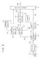
- FIG. 5 is a block diagram showing a transform coding apparatus as a first embodiment of the invention;
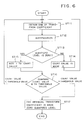
- FIG. 6 is a flow chart illustrating operation of the transform coding apparatus shown in FIG. 5;
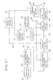
- FIG. 7 is a block diagram showing a transform coding apparatus as a second embodiment of the invention;
- FIG. 8 is a flow chart illustrating operation of the transform coding apparatus shown in FIG. 7;
- FIG. 9 is a block diagram showing a transform coding apparatus as a third embodiment of the invention;
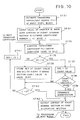
- FIG. 10 is a flow chart illustrating operation of the transform coding apparatus shown in FIG. 9;
- FIG. 11 is a block diagram showing a transform coding apparatus as a fourth embodiment of the invention; and
- FIG. 12 is a flow chart illustrating operation of the transform coding apparatus shown in FIG. 11.
- A first embodiment of the invention will now be described based on FIG. 5 and FIG. 6. In FIG. 5, numeral 21 designates a linear transform section for performing linear transform of blocked signals in the predetermined order, numeral 22 designates a counter for counting the number of the consecutive zero quantized levels, numeral 23 designates a decision section for comparing the count value with the threshold value and performing decision whether the linear transform of next coefficient should be performed or not, numeral 24 designates a zero coefficient output section for outputting the zero quantized levels of the given number, and numeral 25 designates a threshold setting section for setting the threshold value. Constitution of the embodiment is similar to that shown in FIG. 4 except that as above described.
- Next, operation will be described. In similar manner to the apparatus shown in FIG. 4, digitized input image signals 101 by one frame are divided into two-dimensional blocks by the
blocking section 1, and become blocked image signals 102. Thelinear transform section 2 applies the linear transform to the blocked image signals 102 in the order shown by arrow in FIG. 2 for example, and outputs a transform coefficient 121 (step ST11). Thequantization section 4 quantizes thetransform coefficients 121 in givenquantization characteristics 115, and outputs quantization coefficients 120 (step ST12). The counter 22 counts the number of the consecutivequantized levels 120 having value zero (steps ST13, ST15). If the non-zeroquantized level 120 is outputted from thequantization section 4, thecount value 122 is reset and becomes zero (step ST14). Thedecision section 23 compares the inputtedcount value 122 with thethreshold value 123 given from the threshold setting section, and process is branched to following processing (step ST16). - (I) If count value < threshold value, the
decision section 23 outputs thedecision result 124 indicating that next coefficient is estimated by the linear transform to thelinear transform section 21. Then thelinear transform section 21 performs the linear transform continuously. - (II) If count value = threshold value, the
decision section 23 outputs thedecision result 124 indicating that the linear transform is not performed from next coefficient to last coefficient to thelinear transform section 21, and outputs thenumber 125 of coefficients where the linear transform is not performed. The zerocoefficient output section 24 for outputting the zero quantizedlevel series 126 of the givennumber 125 to the coding section 5 (step ST17). - As already described, in general, since the intensity of the transform coefficients becomes weak from lower frequency components to higher frequency components, the quantized levels become zero consecutively with high probability at higher frequency components. Consequently, when the quantization is performed in the order from lower frequency components to higher frequency components and the zero quantized levels are counted, at the small threshold value, since the above-mentioned condition (II) is satisfied at coefficients of relatively lower frequency components, the processing time required to estimate the transform coefficients can be significantly reduced.
- The
coding section 5 allocates codes based on thequantization characteristics 115 used in thequantization section 4, thequantization coefficients 120 and the zeroquantization coefficient series 126, and transmits thecodes 128 to the transmission line or the like. Also thecontrol section 14 controls thequantization characteristics 115 and thethreshold value 127 adaptively by the amount of the coded bits of the input image. That is, in order to decrease the amount of the coded bits of the input image, since the quantization must be effected coarsely, thequantization characteristics 115 are made large and thethreshold value 127 is made small so that the transmission to higher frequency components is not performed. On the contrary, in order to increase the amount of the coded bits, since the quantization must be effected finely, thequantization characteristics 115 are made small and thethreshold value 127 is made large so that the transmission to higher frequency components is performed and the picture quality of the decoded image is not deteriorated. - Although combination of the two-dimensional linear transform and the quantization has been described in the above embodiment, similar effects can be obtained also in combination of the one-dimensional or three-dimensional linear transform and the quantization.
- A second embodiment of the invention will be described based on FIG. 7 and FIG. 8.
Numeral 31 designates a quantization section for controlled bydecision result 138 and performing quantization, numeral 32 designates a threshold setting section for setting the threshold value based onbuffer occupancy 134, and numeral 33 designates a decision section for comparing thecount value 136 of thecounter 22 with thethreshold value 137. - Next, operation will be described. Digitized input image signals 101 by one frame are blocked and then subjected to linear transform. The
scan transform section 3 rearranges the transform coefficients, and thequantization section 31 quantizes thetransform coefficients 104 by the givenquantization step size 135 and outputs the quantization coefficient series 131 (step ST22). Thecoding control section 7 determines thequantization step size 135 from thebuffer occupancy 134 of thetransmission buffer 6, and outputs it to thequantization section 31. Thethreshold setting section 32 determines thethreshold value 137 also from thebuffer occupancy 134, and outputs it to thedecision section 33. The counter 22 counts the number of the consecutive zero values among the quantizedlevel series 131, and if the non-zero quantized level is outputted from thequantization section 31, thecount value 136 is reset and becomes zero (step ST24). Thedecision section 33 compares the inputtedcount value 136 with thethreshold value 137 given from thethreshold setting section 32, and outputs thedecision result 138 to thequantization section 31. Thequantization section 31 is branched to following processing according to the decision result 138 (step ST26). - (I) If the
decision result 138 indicates that count value < threshold value, next coefficient is quantized also in the samequantization step size 135. - (II) If the
decision result 138 indicates that count value = threshold value, the quantization is not performed and the zero quantized levels are outputted from next coefficient to the last coefficient. - In the FIG. 3, for example, when the threshold value is set to 4 or 5, the event and the number of the coefficients performing the quantization become as follows.
- When the threshold value is 4, the event becomes (0, 20), (2, 15), EOB, and the number of the coefficients performing the quantization becomes eight from Q(0, 0) to Q(2, 1).
- When the threshold value is 5, the event becomes (0, 20), (2, 15), (4, 5), (3, 2), EOB, and the number of the coefficients performing the quantization becomes 18 from Q(0, 0) to Q(3, 2).
- As already described, in general, since the intensity of the transform coefficients becomes weak from lower frequency components to higher frequency components, the quantized levels Q(u, v) being a result of the quantization become zero consecutively with high probability at higher frequency components. Consequently, when the quantization is performed in the order from lower frequency components to higher frequency components and the zero quantized levels are counted, at the small threshold value (111), since the above-mentioned condition (II) is satisfied at coefficients of relatively lower frequency components, the number of the operations and the amount of the coded bits to enable the stopping of quantization and coding of the transform coefficients of higher frequency components can be reduced. Consequently, in the apparatus of the prior art shown in FIG. 1, since the amount of the coded bits is controlled only by the
quantization step size 109, the amount of the coded bits varied rapidly depending on whether thequantization step size 109 is large or small, however, thethreshold setting section 32 controls thethreshold value 137 adaptively thereby the rapid variation of the amount of the coded bits can be suppressed. That is, when thebuffer occupancy 134 is little, thethreshold value 137 is made small and the coefficient transmission range is limited thereby the amount of the coded bit at the smallquantization step size 135 can be suppressed. On the contrary, when thebuffer occupancy 134 is large, thethreshold value 137 is set large thereby coefficients to higher frequency components can be transmitted and the deterioration of the picture quality of the decoded image can be prevented. - Also according to this embodiment, since all transform coefficients need not be necessarily quantized, when the quantization is executed using the digital signal processor or the like, the number of the operations can be significantly reduced and further effects can be obtained.
- Although combination of the two-dimensional linear transform and the quantization has been described in the above embodiment, similar effects can be obtained also in combination of the one-dimensional or three-dimensional linear transform and the quantization.
- As above described, according to this embodiment, since decision whether the subsequent transform coefficients should be quantized and coded or not is performed depending on the number of the consecutive zero quantized levels, effects are obtained in that the processing time and the amount of the coded bit required for the quantization can be significantly reduced without deteriorating the picture quality of the decoded image.
- Next, a third embodiment of the invention will be described based on FIG. 9 and FIG. 10. In FIG. 9, numeral 42 designates an event storage section for temporarily storing an event comprising value of non-zero quantized level among the quantized
level 131 andcount value 136 at that time, and numeral 43 designates a code allocation section for allocating codes to the event. - Next, operation will be described.
- Digitized input image signals 101 by one frame are divided into blocks of N x N pixels, and then subjected to linear transform. The
scan transform section 3 rearranges the transform coefficients, and outputs the transform coefficient series F(n) 104 (step ST31). Thecoding control section 7 determines thequantization step size 135 from thebuffer occupancy 134 of thetransmission buffer 6, and outputs it to thequantization section 31. Thethreshold setting section 32 determines thethreshold value 137 also from thebuffer occupancy 134, and outputs it to thedecision section 33. As the initial setting, thecount value 136 of thecounter 22 is made zero, and the storage content of theevent storage section 42 is cleared, and the coefficient number i of the transform coefficient series F(n) 104 constituted by the transform coefficients of N² is made 1 (step ST32). Thequantization section 31 quantizes F(i) being one of the transform coefficient series F(n) 104 in thequantization step size 135, and outputs Q(i) being one of the quantized level series Q(n) 131 (step ST34). If the value of Q(i) is not zero, theevent storage section 42 stores set comprising thecount value 136 of thecounter 22 and Q(i) being non-zero quantized level as an event. And then thecounter 22 is reset and thecount value 136 becomes zero (step ST36). If Q(i) is not the last quantized level, quantization of next transform coefficient is performed continuously (steps ST40, ST41). If the value of Q(i) is zero, thecounter 22 adds 1 to the count value 136 (step 37). Next thedecision section 33 compares the inputtedcount value 136 with thethreshold value 137, and outputs thedecision result 138 to theevent storage section 42. If thedecision result 138 indicates that count value (138) = threshold value (137) (step ST38), or if Q(i) is the last quantized level of the quantized level series Q(n) (step ST40), theevent storage section 42 outputs theevent 142 stored at present, and the processing of the pixel block terminates (step ST42). Thecode allocation section 43 allocates Huffman codes and adds EOB to the outputtedevent 142, and outputs the codeddata 143 to thetransmission buffer 6. On the contrary, if there is noevent 142 to be outputted, since it is an insignificant block, code representing the insignificant block is outputted as the codeddata 143 to thetransmission buffer 6. - On the other hand, the quantization in the
quantization section 31 is controlled by thedecision result 138 from thedecision section 33, and if count value (136) = threshold value (137), the quantization processing is terminated for the subsequent transform coefficients. - In the FIG. 3, for example, when the threshold value is set to 4 or 5, the event stored in the
event storage section 42 and the number of the coefficients performing the quantization respectively become as follows. - When the threshold value is 4, since the four zero quantized levels continue from Q(5) to Q(8), the condition of terminating the quantization is satisfied and the event stored as set of the zero run and the value of the non-zero quantized level is (0, 20), (2, 15), and the number of the transform coefficients performing the quantization becomes eight from Q(1) to Q(8).
- When the threshold value is 5, since the five zero coefficients continue from Q(14) to Q(18), the stored event is (0, 20), (2, 15), (4, 5), (3, 2), and the number of the coefficients performing the quantization becomes 18 from Q(1) to Q(18).
- As already described, in general, since the intensity of the transform coefficients becomes weak from lower frequency components to higher frequency components, the quantized level series Q(n) 131 being a result of the quantization becomes zero consecutively with high probability as n becomes large. Consequently, as the
threshold value 137 is made small, the transmission range of the coefficients is limited and the number of the coefficients requiring the quantization becomes little and the amount of the coded bits is also decreased. Consequently, if thethreshold value 137 is controlled in feedback adaptively from thebuffer occupancy 134 in similar manner to thequantization step size 135, the amount of the coded bits can be smoothed more finely. - According to this embodiment, since all transform coefficients are not necessarily quantized, when necessary transform coefficients only are obtained, the number of the operation to obtain the transform coefficients can be reduced and further effects can be obtained.
- Although combination of the two-dimensional linear transform and the quantization has been described in the above embodiment, similar effects can be obtained also in combination of the one-dimensional or three-dimensional linear transform and the quantization.
- Next, a fourth embodiment of the invention will be described based on FIG. 11 and FIG. 12. In FIG. 11, numeral 50 designates a one-dimensional linear transform section for performing one-dimensional linear transform of the blocked image signals 102, and numeral 51 designates another one-dimensional linear transform section for performing one-dimensional linear transform of outputs of the one-dimensional
linear transform section 50 in other direction. - Next, operation will be described.
- Digitized input image signals 101 by one frame are divided into blocks of N x N pixels by the
blocking section 1. The blocked image signals 102 are subjected to, for example, the one-dimensional linear transform operation in the row direction by the one-dimensionallinear transform section 50, and become one-dimensional transform coefficient block 151 having N x N elements (step ST51). As the initial setting, thecount value 136 of thecounter 22 is made zero, and the storage content of theevent storage section 42 is cleared, and the coefficient number i of the two-dimensional transform coefficients of N² pieces scanned in the scan order shown in FIG. 2 is made 1 (step ST52). Next, the one-dimensionallinear transform section 51 performs the one-dimensional linear transform operation in the column direction being orthogonal to the one-dimensionallinear transform block 151, and one of the two-dimensional transform coefficient F(i) of the coefficient number i is outputted (step ST53). Thecoding control section 7 determines thequantization step size 135 from thebuffer occupancy 134 of thetransmission buffer 6, and outputs it to thequantization section 41. Thethreshold setting section 32 determines thethreshold value 137 also from thebuffer occupancy 134, and outputs it to thedecision section 33. Thequantization section 41 quantizes the transform coefficient F(i) 152 in thequantization step size 135, and outputs the quantized level Q(i) 153 (step ST54). Next, decision is performed regarding whether the quantized level Q(i) is zero or not (step ST55). If the value of Q(i) is not zero, theevent storage section 42 stores set comprising thecount value 136 of thecounter 22 and Q(i) being non-zero quantized level as an event. In this case, thecounter 22 makes thecount value 22 zero (step ST56). On the other hand, if the quantization coefficient Q(i) is zero in the step ST55, thecounter 22 adds 1 to the count value 136 (step ST57). Thedecision section 33 compares thecount value 136 with the threshold value 137 (step ST58), and outputs thedecision result 138. If thedecision result 138 indicates that thecount value 136 is equal to or more than thethreshold value 137, the one-dimensionallinear transform section 51 and thequantization section 41 stop the processing (step ST59). Set of the number of the zero coefficients among the quantized levels and the value of the non-zero quantized levels stored in theevent storage section 42 is outputted to the code allocation section 43 (step ST62). In the comparison of thecount value 136 with thethreshold value 137 in thedecision section 33 as above described, if thecount value 136 is less than thethreshold value 137 or if the processing in the step ST56 terminates, theevent storage section 42 performs decision whether the coefficient number i becomes N² or not (step ST60). If the coefficient number i is N², i.e., Q(i) is the last quantized level, theevent storage section 42 outputs theevent 154 stored at present (step ST62), and the processing of the pixel block ends. Thecode allocation section 43 allocates Huffman codes and adds EOB to the outputtedevent 154, and outputs the codeddata 155 to thetransmission buffer 6. On the contrary, if there is noevent 155 to be outputted, since it is an insignificant block, code representing the insignificant block is outputted as the codeddata 155 to thetransmission buffer 6. If the coefficient number i is N² or less and Q(i) is not the last quantized level, 1 is added to the coefficient number i (step ST61), and the operation and quantization of next two-dimensional transform coefficient F(i) are performed continuously. - According to this embodiment, since all two-dimensional transform coefficients are not always necessary, at the one-dimensional linear transform operation of the first time, only the one-dimensional transform coefficients necessary to estimate the two-dimensional transform coefficients are estimated, thereby the number of the operation to obtain the transform coefficients can be reduced and further effects can be obtained.
Claims (6)
- A transform coding apparatus wherein a linear transform operation is performed on an input signal series, and transform coefficients are quantized and coded in sequence from the lower frequency components to the higher frequency components in the transform region, said transform coding apparatus comprising: partitioning means (1) for partitioning said input signal series (101) into signal blocks;
linear transform means (2; 21) for performing a linear transform operation on the signal blocks (102) and for obtaining a series of transform coefficients (104; 121) in sequence from the lower frequency components to the higher frequency components;
quantization means (4; 31) for quantizing in sequence each of said transform coefficients (104; 121) in said series of transform coefficients (104; 121) outputted from said linear transform means (2; 21) counting means (22) for counting the number of consecutive zero quantized levels in the quantized transform coefficients (120; 131) quantized by said quantization means (4; 31) and for outputting the count values (122; 136) thereof;
threshold determining means (25; 32) for determining the threshold value (123; 137) of the number of consecutive zero quantized levels to be transmitted;
zero quantized level output means (24) for outputting zero quantized levels (126) when activated;
coding means (5; 43) for coding the outputs (120; 131) of said quantization means (4; 31);
a transmission buffer (6) for storing codes (128; 132) outputted by said coding means (5; 43); and
control means (7; 14) for determining the size of the quantization step used by said quantization means (4; 31) based on the buffer occupancy of said transmission buffer (6);
characterized by
decision means (23; 33) for obtaining one additional transform coefficient from said linear transform means (2; 21) when and only when the count value (122; 136) of consecutive zero quantized levels is less than the threshold value (123; 137), and for activating said zero quantized level output means (24) for subsequent transform coefficients when said count value (122; 136) equals said threshold value (123; 137); and
said threshold determining means (25; 32) determining said threshold value (123; 137) based on the buffer occupancy of said transmission buffer (6). - A transform coding apparatus as set forth in claim 1, wherein said threshold determining means (25; 32) outputs the threshold value determined previously.
- A transform coding apparatus as set forth in claim 1, wherein said threshold determining means (25; 32) decreases said threshold value (123; 137) when the buffer occupancy of said transmission buffer (6) is at a low value.
- A transform coding apparatus as set forth in claim 1, characterized by
scan transform means (3) for rearranging the transform coefficients (103) outputted from said linear transform means (2) in sequence from the lower frequency components to the higher frequency components; and
event storage means for storing as events of the block the value of quantized transform coefficients which are non-zero quantized levels and the number of consecutive zero quantized levels counted by said counting means (22) before said non-zero quantized levels appear;
said coding means (5; 43) allocating codes to each event stored in said event storage means; and
said decision means quantizing one additional transform coefficient in said quantizing means when said count value of consecutive zero quantized levels counted by said counting means is less than said threshold value and terminating the quantization of subsequent transform coefficients when said count value equals said threshold value. - A transform coding apparatus wherein a two-dimensional linear transform operation is performed on an input signal series, and transform coefficients are quantized and coded in sequence from lower frequency components to higher frequency components in the transform region, said transform coding apparatus comprising: partitioning means (1) for partitioning said input signal series (101) into input signal blocks (102);
first transform means (50) for applying a one-dimensional linear transform operation to the partitioned input signal blocks (102) so as to obtain a one-dimensional transform coefficient block (151);
second transform means (51) for further applying an orthogonal one-dimensional linear transform operation to the one-dimensional transform coefficient block (151) so as to obtain a series of two-dimensional cofficients (152) in sequence from the lower frequency components to the higher frequency components;
quantizing means (41) for quantizing each two-dimensional transform coefficient (152) outputted from said second transform means (51);
counting means (22) for counting the number of consecutive zero quantized levels in the values of the quantized transform coefficients quantized by said quantizing means and for outputting the count values thereof;
threshold determining means (32) for determining the threshold of the number of consecutive zero quantized levels to be transmitted;
event storage means (42) for storing as events of the block the value of quantized transform coefficients which are non-zero quantized levels and the number of consecutive zero quantized levels (136) counted by said counting means (22) before the non-zero quantized levels appear;
coding means (43) for allocating codes to each event stored in said event storage means (42);
a transmission buffer (6) for storing codes outputted by said coding means (43); and
control means (7) for determining size of quantization step used by said quantization means (41) based on the buffer occupancy of said transmission buffer (6);
characterized by
decision means (33) for obtaining one further two-dimensional transform coefficient from said second transform means when said value of consecutive zero quantized levels is less than said threshold value and for terminating the second transform and quantizing process for subsequent two-dimensional transform coefficients when said count value equals said threshold value; and
said threshold determining means (32) determining said threshold value based on the buffer occupancy of said transmission buffer (6). - A transform coding apparatus as set forth in claim 5, wherein said threshold determining means (32) decreases said threshold value when the buffer occupancy of said transmission buffer (6) is at a low value.
Applications Claiming Priority (8)
| Application Number | Priority Date | Filing Date | Title |
|---|---|---|---|
| JP213622/89 | 1989-08-19 | ||
| JP21362289A JP2503678B2 (en) | 1989-08-19 | 1989-08-19 | Transform coding method |
| JP324527/89 | 1989-12-13 | ||
| JP32452789A JP2503698B2 (en) | 1989-12-13 | 1989-12-13 | Transform coding method |
| JP11500/90 | 1990-01-19 | ||
| JP2011500A JP2503706B2 (en) | 1990-01-19 | 1990-01-19 | Transform coding method |
| JP34658/90 | 1990-02-15 | ||
| JP2034658A JPH0822064B2 (en) | 1990-02-15 | 1990-02-15 | Transform coding method |
Publications (3)
| Publication Number | Publication Date |
|---|---|
| EP0414074A2 EP0414074A2 (en) | 1991-02-27 |
| EP0414074A3 EP0414074A3 (en) | 1992-11-25 |
| EP0414074B1 true EP0414074B1 (en) | 1995-02-15 |
Family
ID=27455612
Family Applications (1)
| Application Number | Title | Priority Date | Filing Date |
|---|---|---|---|
| EP90115439A Expired - Lifetime EP0414074B1 (en) | 1989-08-19 | 1990-08-11 | Transform coding apparatus |
Country Status (8)
| Country | Link |
|---|---|
| US (1) | US5086488A (en) |
| EP (1) | EP0414074B1 (en) |
| KR (1) | KR930009872B1 (en) |
| AU (1) | AU622572B2 (en) |
| CA (1) | CA2023440C (en) |
| DE (1) | DE69016880T2 (en) |
| FI (1) | FI98111C (en) |
| NO (1) | NO303480B1 (en) |
Families Citing this family (69)
| Publication number | Priority date | Publication date | Assignee | Title |
|---|---|---|---|---|
| JPH0379182A (en) * | 1989-08-23 | 1991-04-04 | Fujitsu Ltd | Image encoding control system |
| US5875266A (en) * | 1990-07-31 | 1999-02-23 | Fujitsu Limited | Image data processing a method and apparatus |
| DE69131808T2 (en) | 1990-07-31 | 2000-03-16 | Fujitsu Ltd | Process and device for image data processing |
| US5933538A (en) * | 1990-07-31 | 1999-08-03 | Fujitsu Limited | Image data processing method and apparatus |
| US7142720B1 (en) | 1990-07-31 | 2006-11-28 | Fujitsu Limited | Image data processing method and apparatus |
| US5657399A (en) * | 1991-05-17 | 1997-08-12 | Canon Kabushiki Kaisha | Encoding/decoding apparatus using quantizing steps information |
| JP2670201B2 (en) * | 1991-08-30 | 1997-10-29 | 富士写真フイルム株式会社 | Image data compression encoding apparatus and method |
| US5838834A (en) * | 1991-11-07 | 1998-11-17 | Canon Kabushiki Kaisha | Image processing apparatus and method for quantizing image data and quantization errors using single quantizing unit and pluralities of quantization tables |
| US5339368A (en) * | 1991-11-21 | 1994-08-16 | Unisys Corporation | Document image compression system and method |
| US6028961A (en) * | 1992-07-31 | 2000-02-22 | Canon Kabushiki Kaisha | Image processing method and apparatus |
| DE69331126T2 (en) * | 1992-07-31 | 2002-06-20 | Canon Kk | Image processing device and method for multi-stage compression |
| EP0610604A1 (en) * | 1993-02-11 | 1994-08-17 | Agfa-Gevaert N.V. | Multiple processing of radiographic images based on a pyramidal image decomposition |
| JPH06292019A (en) * | 1993-04-02 | 1994-10-18 | Fujitsu Ltd | Picture data compressor and picture code compressor |
| CN1092446C (en) * | 1993-05-31 | 2002-10-09 | 佳能株式会社 | Image processing method and apparatus |
| JP3247804B2 (en) * | 1993-08-17 | 2002-01-21 | 株式会社リコー | Data compression method, data compression / decompression method, code word data number limiting device |
| US5610657A (en) * | 1993-09-14 | 1997-03-11 | Envistech Inc. | Video compression using an iterative error data coding method |
| JPH0787327A (en) * | 1993-09-17 | 1995-03-31 | Fuji Xerox Co Ltd | Image coding device |
| KR0183688B1 (en) * | 1994-01-12 | 1999-05-01 | 김광호 | Image encoding method and device |
| JP3532963B2 (en) * | 1994-05-31 | 2004-05-31 | ペンタックス株式会社 | Image compression device |
| US5553160A (en) * | 1994-09-01 | 1996-09-03 | Intel Corporation | Method and apparatus for dynamically selecting an image compression process based on image size and color resolution |
| JPH08181987A (en) * | 1994-12-22 | 1996-07-12 | Canon Inc | Coder |
| US7426311B1 (en) * | 1995-10-26 | 2008-09-16 | Hyundai Electronics Industries Co. Ltd. | Object-based coding and decoding apparatuses and methods for image signals |
| US6072909A (en) * | 1995-12-13 | 2000-06-06 | Fuji Xerox Co., Ltd. | Image coding devise and image decoding devise using with image disassembly |
| JP3681828B2 (en) * | 1996-08-14 | 2005-08-10 | 富士写真フイルム株式会社 | Code amount control method and apparatus for image data |
| US6603884B2 (en) * | 1997-05-08 | 2003-08-05 | Ricoh Company, Ltd. | Image processing system for compressing image data including binary image data and continuous tone image data by a sub-band transform method with a high-compression rate |
| FI107496B (en) * | 1997-07-18 | 2001-08-15 | Nokia Mobile Phones Ltd | Image Compressor Call |
| US6937659B1 (en) | 1997-11-14 | 2005-08-30 | Ac Capital Management, Inc. | Apparatus and method for compressing video information |
| GB2333656B (en) * | 1998-01-22 | 2002-08-14 | British Broadcasting Corp | Compressed signals |
| GB2333657B (en) | 1998-01-22 | 2002-08-21 | Snell & Wilcox Ltd | Video signal compression |
| GB2335104B (en) | 1998-03-06 | 2002-01-30 | British Broadcasting Corp | Cascading of up conversion and down conversion |
| GB2337389B (en) | 1998-05-15 | 2002-05-29 | Snell & Wilcox Ltd | Video signal processing |
| US6459731B1 (en) * | 1998-08-28 | 2002-10-01 | Lucent Technologies Inc. | Technique for video communications using a coding-matched filter arrangement |
| GB9822094D0 (en) | 1998-10-09 | 1998-12-02 | Snell & Wilcox Ltd | Improvements in data compression |
| GB9822087D0 (en) | 1998-10-09 | 1998-12-02 | Snell & Wilcox Ltd | Improvements in data compression |
| GB9822092D0 (en) * | 1998-10-09 | 1998-12-02 | Snell & Wilcox Ltd | Analysis of compression decoded sequences |
| GB9824061D0 (en) | 1998-11-03 | 1998-12-30 | Snell & Wilcox Ltd | Film sequence detection (nt4) |
| US6700623B1 (en) | 1998-12-10 | 2004-03-02 | Snell & Wilcox Limited | Video signal processing using triplets of pixels |
| JP3603000B2 (en) * | 2000-02-01 | 2004-12-15 | カネボウ株式会社 | Huffman encoding apparatus, Huffman encoding method, and recording medium recording Huffman encoding processing program |
| KR100683380B1 (en) * | 2000-02-21 | 2007-02-15 | 주식회사 팬택앤큐리텔 | Method and apparatus for transformation and inverse transformation of image for image compression coding |
| GB2361126B (en) * | 2000-04-05 | 2004-04-21 | Snell & Wilcox Ltd | Spatial video processing |
| US6879652B1 (en) * | 2000-07-14 | 2005-04-12 | Nielsen Media Research, Inc. | Method for encoding an input signal |
| JP3833177B2 (en) * | 2000-11-30 | 2006-10-11 | キヤノン株式会社 | Image processing apparatus, image processing method, storage medium, and program |
| JP4336789B2 (en) * | 2002-01-10 | 2009-09-30 | 日本電気株式会社 | Two-dimensional orthogonal transform and quantization method, apparatus and program thereof |
| US9577667B2 (en) * | 2002-04-23 | 2017-02-21 | Ntt Docomo, Inc. | System and method for arithmetic encoding and decoding |
| ES2552696T3 (en) * | 2002-04-23 | 2015-12-01 | Ntt Docomo, Inc. | System and method for arithmetic coding and decoding |
| US7073505B2 (en) * | 2002-09-06 | 2006-07-11 | Apneon, Inc. | Systems and methods for moving and/or restraining tissue in the oral cavity |
| US7212681B1 (en) | 2003-01-15 | 2007-05-01 | Cisco Technology, Inc. | Extension of two-dimensional variable length coding for image compression |
| US7194137B2 (en) * | 2003-05-16 | 2007-03-20 | Cisco Technology, Inc. | Variable length coding method and apparatus for video compression |
| US7570818B2 (en) * | 2003-10-17 | 2009-08-04 | Hewlett-Packard Development Company, L.P. | Method for deblocking and transcoding a media stream |
| US7499595B2 (en) * | 2004-08-18 | 2009-03-03 | Cisco Technology, Inc. | Joint amplitude and position coding for photographic image and video coding |
| US7454076B2 (en) * | 2004-06-15 | 2008-11-18 | Cisco Technology, Inc. | Hybrid variable length coding method for low bit rate video coding |
| US7499596B2 (en) * | 2004-08-18 | 2009-03-03 | Cisco Technology, Inc. | Amplitude coding for clustered transform coefficients |
| US7492956B2 (en) * | 2004-08-18 | 2009-02-17 | Cisco Technology, Inc. | Video coding using multi-dimensional amplitude coding and 2-D non-zero/zero cluster position coding |
| US7471840B2 (en) * | 2004-08-18 | 2008-12-30 | Cisco Technology, Inc. | Two-dimensional variable length coding of runs of zero and non-zero transform coefficients for image compression |
| US7471841B2 (en) * | 2004-06-15 | 2008-12-30 | Cisco Technology, Inc. | Adaptive breakpoint for hybrid variable length coding |
| US7454073B2 (en) * | 2004-06-15 | 2008-11-18 | Cisco Technology, Inc. | Video compression using multiple variable length coding processes for multiple classes of transform coefficient blocks |
| US7680349B2 (en) * | 2004-08-18 | 2010-03-16 | Cisco Technology, Inc. | Variable length coding for clustered transform coefficients in video compression |
| US7620258B2 (en) * | 2004-08-18 | 2009-11-17 | Cisco Technology, Inc. | Extended amplitude coding for clustered transform coefficients |
| US8031768B2 (en) * | 2004-12-15 | 2011-10-04 | Maxim Integrated Products, Inc. | System and method for performing optimized quantization via quantization re-scaling |
| US7672518B2 (en) * | 2005-03-29 | 2010-03-02 | Eastman Kodak Company | Use of frequency transform in the analysis of image sensors |
| US7672519B2 (en) * | 2005-03-29 | 2010-03-02 | Eastman Kodak Company | Use of frequency transforms in the analysis of image sensors |
| US8121428B2 (en) * | 2005-05-31 | 2012-02-21 | Microsoft Corporation | Accelerated image rendering |
| US7242328B1 (en) * | 2006-02-03 | 2007-07-10 | Cisco Technology, Inc. | Variable length coding for sparse coefficients |
| CA2679255C (en) * | 2007-03-14 | 2013-04-30 | Nippon Telegraph And Telephone Corporation | Code amount estimating method and apparatus, and program and storage medium therefor |
| KR101083379B1 (en) * | 2007-03-14 | 2011-11-14 | 니폰덴신뎅와 가부시키가이샤 | Motion vector searching method and device, and record medium having recorded the program therefor |
| KR101075606B1 (en) * | 2007-03-14 | 2011-10-20 | 니폰덴신뎅와 가부시키가이샤 | Quantization control method, device, program, and recording medium containing the program |
| KR101394153B1 (en) * | 2007-12-11 | 2014-05-16 | 삼성전자주식회사 | Method and apparatus for quantization, and Method and apparatus for inverse quantization |
| US8654859B1 (en) | 2009-12-17 | 2014-02-18 | Ambarella, Inc. | Low cost rate-distortion computations for video compression |
| US9641846B2 (en) | 2010-10-22 | 2017-05-02 | Qualcomm Incorporated | Adaptive scanning of transform coefficients for video coding |
Family Cites Families (6)
| Publication number | Priority date | Publication date | Assignee | Title |
|---|---|---|---|---|
| AU579441B2 (en) * | 1985-01-16 | 1988-11-24 | Mitsubishi Denki Kabushiki Kaisha | Video encoding apparatus |
| JPS61292434A (en) * | 1985-05-17 | 1986-12-23 | Fujitsu Ltd | Buffer memory |
| EP0260748B1 (en) * | 1986-09-13 | 1994-07-13 | Philips Patentverwaltung GmbH | Bitrate reduction method and circuitry |
| US4698672A (en) * | 1986-10-27 | 1987-10-06 | Compression Labs, Inc. | Coding system for reducing redundancy |
| CA1296430C (en) * | 1986-11-10 | 1992-02-25 | Masahide Kaneko | Encoding system capable of accomplishing a high efficiency by anterior and/or posterior processing to quantization |
| US4922273A (en) * | 1987-04-02 | 1990-05-01 | Konica Corporation | Compression method of halftone image data |
-
1990
- 1990-08-09 US US07/564,824 patent/US5086488A/en not_active Expired - Lifetime
- 1990-08-11 DE DE69016880T patent/DE69016880T2/en not_active Expired - Lifetime
- 1990-08-11 EP EP90115439A patent/EP0414074B1/en not_active Expired - Lifetime
- 1990-08-13 KR KR1019900012397A patent/KR930009872B1/en not_active IP Right Cessation
- 1990-08-13 FI FI903989A patent/FI98111C/en active IP Right Grant
- 1990-08-16 NO NO903624A patent/NO303480B1/en not_active IP Right Cessation
- 1990-08-16 AU AU61069/90A patent/AU622572B2/en not_active Expired
- 1990-08-16 CA CA002023440A patent/CA2023440C/en not_active Expired - Fee Related
Non-Patent Citations (2)
| Title |
|---|
| IEE Transactions on communications,vol.COM-32,nr.3,March 1984,pages 225-232 * |
| IEEE Transactions on communications,vol. COM-32,nr.3,March 1984, pages 225-232 * |
Also Published As
| Publication number | Publication date |
|---|---|
| NO903624L (en) | 1991-02-20 |
| DE69016880T2 (en) | 1995-09-21 |
| DE69016880D1 (en) | 1995-03-23 |
| AU6106990A (en) | 1991-02-21 |
| EP0414074A3 (en) | 1992-11-25 |
| KR910005691A (en) | 1991-03-30 |
| EP0414074A2 (en) | 1991-02-27 |
| FI903989A0 (en) | 1990-08-13 |
| KR930009872B1 (en) | 1993-10-12 |
| FI98111C (en) | 1997-04-10 |
| US5086488A (en) | 1992-02-04 |
| AU622572B2 (en) | 1992-04-09 |
| CA2023440A1 (en) | 1991-02-20 |
| NO303480B1 (en) | 1998-07-13 |
| FI98111B (en) | 1996-12-31 |
| NO903624D0 (en) | 1990-08-16 |
| CA2023440C (en) | 1994-11-08 |
Similar Documents
| Publication | Publication Date | Title |
|---|---|---|
| EP0414074B1 (en) | Transform coding apparatus | |
| US6198848B1 (en) | Method and apparatus for compressing and storing data indicative of a full-color image | |
| US6985632B2 (en) | Image processing system, image processing apparatus, and image processing method | |
| US6324304B1 (en) | Picture coding apparatus and method thereof | |
| US5699457A (en) | Image compression coder having improved bit rate control and block allocation | |
| US5287200A (en) | Block adaptive linear predictive coding with multi-dimensional adaptive gain and bias | |
| EP0708551B1 (en) | Image signal coding apparatus with switching between variable-length coding and fixed-length coding | |
| EP0861003B1 (en) | Code-amount control device and video coding device including the code-amount control device | |
| US20080095455A1 (en) | Image encoding apparatus and control method thereof | |
| US6968088B2 (en) | Modification of detected quantization step size from the encoded bitstream based on a region of interest (ROI) bitmask | |
| JPH07123269A (en) | Corder for picture signal | |
| US6915014B1 (en) | Image processing apparatus and method | |
| US6546145B1 (en) | Image compression using selection of quantization method | |
| EP0659023B1 (en) | Method and apparatus for compression-coding image data | |
| US6023297A (en) | Encoding method and encoder using it | |
| JP2908459B2 (en) | Image coding method | |
| JP2503706B2 (en) | Transform coding method | |
| US7606436B2 (en) | Image encoding apparatus and quantization control method | |
| JP2839142B2 (en) | Image coding method | |
| US6408097B1 (en) | Picture coding apparatus and method thereof | |
| JP2872257B2 (en) | Image data compression device | |
| JPH06350992A (en) | Data compression circuit | |
| JP2931328B2 (en) | Image signal compression coding device | |
| JPH0822064B2 (en) | Transform coding method | |
| JP2503698B2 (en) | Transform coding method |
Legal Events
| Date | Code | Title | Description |
|---|---|---|---|
| PUAI | Public reference made under article 153(3) epc to a published international application that has entered the european phase |
Free format text: ORIGINAL CODE: 0009012 |
|
| AK | Designated contracting states |
Kind code of ref document: A2 Designated state(s): DE FR GB IT NL SE |
|
| PUAL | Search report despatched |
Free format text: ORIGINAL CODE: 0009013 |
|
| AK | Designated contracting states |
Kind code of ref document: A3 Designated state(s): DE FR GB IT NL SE |
|
| 17P | Request for examination filed |
Effective date: 19930511 |
|
| 17Q | First examination report despatched |
Effective date: 19930629 |
|
| GRAA | (expected) grant |
Free format text: ORIGINAL CODE: 0009210 |
|
| AK | Designated contracting states |
Kind code of ref document: B1 Designated state(s): DE FR GB IT NL SE |
|
| ITF | It: translation for a ep patent filed |
Owner name: ING. C. GREGORJ S.P.A. |
|
| REF | Corresponds to: |
Ref document number: 69016880 Country of ref document: DE Date of ref document: 19950323 |
|
| ET | Fr: translation filed | ||
| PLBE | No opposition filed within time limit |
Free format text: ORIGINAL CODE: 0009261 |
|
| STAA | Information on the status of an ep patent application or granted ep patent |
Free format text: STATUS: NO OPPOSITION FILED WITHIN TIME LIMIT |
|
| 26N | No opposition filed | ||
| REG | Reference to a national code |
Ref country code: GB Ref legal event code: 746 Effective date: 19960611 |
|
| REG | Reference to a national code |
Ref country code: FR Ref legal event code: D6 |
|
| REG | Reference to a national code |
Ref country code: GB Ref legal event code: IF02 |
|
| PGFP | Annual fee paid to national office [announced via postgrant information from national office to epo] |
Ref country code: DE Payment date: 20090806 Year of fee payment: 20 Ref country code: NL Payment date: 20090816 Year of fee payment: 20 Ref country code: SE Payment date: 20090806 Year of fee payment: 20 Ref country code: GB Payment date: 20090805 Year of fee payment: 20 |
|
| PGFP | Annual fee paid to national office [announced via postgrant information from national office to epo] |
Ref country code: IT Payment date: 20090813 Year of fee payment: 20 Ref country code: FR Payment date: 20091214 Year of fee payment: 20 |
|
| REG | Reference to a national code |
Ref country code: NL Ref legal event code: V4 Effective date: 20100811 |
|
| REG | Reference to a national code |
Ref country code: GB Ref legal event code: PE20 Expiry date: 20100810 |
|
| EUG | Se: european patent has lapsed | ||
| PG25 | Lapsed in a contracting state [announced via postgrant information from national office to epo] |
Ref country code: NL Free format text: LAPSE BECAUSE OF EXPIRATION OF PROTECTION Effective date: 20100811 |
|
| PG25 | Lapsed in a contracting state [announced via postgrant information from national office to epo] |
Ref country code: GB Free format text: LAPSE BECAUSE OF EXPIRATION OF PROTECTION Effective date: 20100810 |
|
| PG25 | Lapsed in a contracting state [announced via postgrant information from national office to epo] |
Ref country code: DE Free format text: LAPSE BECAUSE OF EXPIRATION OF PROTECTION Effective date: 20100811 |