EP0413552B1 - Asymmetric porous polyamide membranes - Google Patents
Asymmetric porous polyamide membranes Download PDFInfo
- Publication number
- EP0413552B1 EP0413552B1 EP90308914A EP90308914A EP0413552B1 EP 0413552 B1 EP0413552 B1 EP 0413552B1 EP 90308914 A EP90308914 A EP 90308914A EP 90308914 A EP90308914 A EP 90308914A EP 0413552 B1 EP0413552 B1 EP 0413552B1
- Authority
- EP
- European Patent Office
- Prior art keywords
- membrane
- polyamide
- membranes
- skin layer
- casting
- Prior art date
- Legal status (The legal status is an assumption and is not a legal conclusion. Google has not performed a legal analysis and makes no representation as to the accuracy of the status listed.)
- Expired - Lifetime
Links
- 239000012528 membrane Substances 0.000 title claims description 231
- 239000004952 Polyamide Substances 0.000 title claims description 61
- 229920002647 polyamide Polymers 0.000 title claims description 61
- 238000005266 casting Methods 0.000 claims description 99
- 239000000243 solution Substances 0.000 claims description 99
- 239000011148 porous material Substances 0.000 claims description 53
- 239000002904 solvent Substances 0.000 claims description 38
- 239000000203 mixture Substances 0.000 claims description 32
- 238000000034 method Methods 0.000 claims description 31
- 229920002302 Nylon 6,6 Polymers 0.000 claims description 23
- 239000000758 substrate Substances 0.000 claims description 23
- LFQSCWFLJHTTHZ-UHFFFAOYSA-N Ethanol Chemical compound CCO LFQSCWFLJHTTHZ-UHFFFAOYSA-N 0.000 claims description 19
- 239000007788 liquid Substances 0.000 claims description 12
- 239000004677 Nylon Substances 0.000 claims description 11
- 229920002292 Nylon 6 Polymers 0.000 claims description 11
- 229920001778 nylon Polymers 0.000 claims description 11
- 230000008569 process Effects 0.000 claims description 9
- 238000001035 drying Methods 0.000 claims description 7
- 230000009477 glass transition Effects 0.000 claims description 6
- 239000011248 coating agent Substances 0.000 claims description 5
- 238000000576 coating method Methods 0.000 claims description 5
- 239000004953 Aliphatic polyamide Substances 0.000 claims description 4
- 229920003231 aliphatic polyamide Polymers 0.000 claims description 4
- 125000004432 carbon atom Chemical group C* 0.000 claims description 4
- 239000012530 fluid Substances 0.000 claims description 4
- 125000001931 aliphatic group Chemical group 0.000 claims description 3
- 239000012266 salt solution Substances 0.000 claims description 3
- 125000000217 alkyl group Chemical group 0.000 claims description 2
- 125000005842 heteroatom Chemical group 0.000 claims description 2
- 230000001376 precipitating effect Effects 0.000 claims description 2
- 229920001577 copolymer Polymers 0.000 claims 1
- 239000010410 layer Substances 0.000 description 70
- OKKJLVBELUTLKV-UHFFFAOYSA-N Methanol Chemical compound OC OKKJLVBELUTLKV-UHFFFAOYSA-N 0.000 description 60
- 239000003570 air Substances 0.000 description 41
- XLYOFNOQVPJJNP-UHFFFAOYSA-N water Substances O XLYOFNOQVPJJNP-UHFFFAOYSA-N 0.000 description 33
- 150000003839 salts Chemical class 0.000 description 19
- -1 polyhexamethylene terephthalamide Polymers 0.000 description 13
- 229920013683 Celanese Polymers 0.000 description 12
- KFZMGEQAYNKOFK-UHFFFAOYSA-N Isopropanol Chemical compound CC(C)O KFZMGEQAYNKOFK-UHFFFAOYSA-N 0.000 description 12
- ZMXDDKWLCZADIW-UHFFFAOYSA-N N,N-Dimethylformamide Chemical compound CN(C)C=O ZMXDDKWLCZADIW-UHFFFAOYSA-N 0.000 description 11
- 238000000108 ultra-filtration Methods 0.000 description 11
- LLSDKQJKOVVTOJ-UHFFFAOYSA-L calcium chloride dihydrate Chemical compound O.O.[Cl-].[Cl-].[Ca+2] LLSDKQJKOVVTOJ-UHFFFAOYSA-L 0.000 description 10
- 229940052299 calcium chloride dihydrate Drugs 0.000 description 10
- 230000004907 flux Effects 0.000 description 10
- 238000011144 upstream manufacturing Methods 0.000 description 9
- ZWEHNKRNPOVVGH-UHFFFAOYSA-N 2-Butanone Chemical compound CCC(C)=O ZWEHNKRNPOVVGH-UHFFFAOYSA-N 0.000 description 8
- CSCPPACGZOOCGX-UHFFFAOYSA-N Acetone Chemical compound CC(C)=O CSCPPACGZOOCGX-UHFFFAOYSA-N 0.000 description 8
- UXVMQQNJUSDDNG-UHFFFAOYSA-L Calcium chloride Chemical compound [Cl-].[Cl-].[Ca+2] UXVMQQNJUSDDNG-UHFFFAOYSA-L 0.000 description 8
- 239000012510 hollow fiber Substances 0.000 description 8
- 239000003495 polar organic solvent Substances 0.000 description 8
- 238000004626 scanning electron microscopy Methods 0.000 description 8
- IJGRMHOSHXDMSA-UHFFFAOYSA-N Atomic nitrogen Chemical compound N#N IJGRMHOSHXDMSA-UHFFFAOYSA-N 0.000 description 7
- 239000001110 calcium chloride Substances 0.000 description 7
- 229910001628 calcium chloride Inorganic materials 0.000 description 7
- 235000011148 calcium chloride Nutrition 0.000 description 7
- 239000000463 material Substances 0.000 description 7
- 229920000139 polyethylene terephthalate Polymers 0.000 description 7
- 239000005020 polyethylene terephthalate Substances 0.000 description 7
- 229920000642 polymer Polymers 0.000 description 7
- 238000005259 measurement Methods 0.000 description 6
- BDAGIHXWWSANSR-UHFFFAOYSA-N methanoic acid Natural products OC=O BDAGIHXWWSANSR-UHFFFAOYSA-N 0.000 description 6
- 238000001471 micro-filtration Methods 0.000 description 6
- 239000002245 particle Substances 0.000 description 6
- 229960002713 calcium chloride Drugs 0.000 description 5
- 239000011521 glass Substances 0.000 description 5
- 229920006100 Vydyne® Polymers 0.000 description 4
- 238000002835 absorbance Methods 0.000 description 4
- 239000000654 additive Substances 0.000 description 4
- 238000005345 coagulation Methods 0.000 description 4
- 230000015271 coagulation Effects 0.000 description 4
- 239000004816 latex Substances 0.000 description 4
- 229920000126 latex Polymers 0.000 description 4
- KWGKDLIKAYFUFQ-UHFFFAOYSA-M lithium chloride Chemical compound [Li+].[Cl-] KWGKDLIKAYFUFQ-UHFFFAOYSA-M 0.000 description 4
- 239000012466 permeate Substances 0.000 description 4
- 238000001556 precipitation Methods 0.000 description 4
- 239000000126 substance Substances 0.000 description 4
- 238000012360 testing method Methods 0.000 description 4
- OSWFIVFLDKOXQC-UHFFFAOYSA-N 4-(3-methoxyphenyl)aniline Chemical compound COC1=CC=CC(C=2C=CC(N)=CC=2)=C1 OSWFIVFLDKOXQC-UHFFFAOYSA-N 0.000 description 3
- WEVYAHXRMPXWCK-UHFFFAOYSA-N Acetonitrile Chemical compound CC#N WEVYAHXRMPXWCK-UHFFFAOYSA-N 0.000 description 3
- 229920002307 Dextran Polymers 0.000 description 3
- 239000004809 Teflon Substances 0.000 description 3
- 229920006362 Teflon® Polymers 0.000 description 3
- 239000012080 ambient air Substances 0.000 description 3
- 230000015572 biosynthetic process Effects 0.000 description 3
- 230000007423 decrease Effects 0.000 description 3
- 229910001873 dinitrogen Inorganic materials 0.000 description 3
- 230000000694 effects Effects 0.000 description 3
- 235000019253 formic acid Nutrition 0.000 description 3
- 238000007654 immersion Methods 0.000 description 3
- 238000002360 preparation method Methods 0.000 description 3
- BDERNNFJNOPAEC-UHFFFAOYSA-N propan-1-ol Chemical compound CCCO BDERNNFJNOPAEC-UHFFFAOYSA-N 0.000 description 3
- 239000010935 stainless steel Substances 0.000 description 3
- 229910001220 stainless steel Inorganic materials 0.000 description 3
- IAZDPXIOMUYVGZ-UHFFFAOYSA-N Dimethylsulphoxide Chemical compound CS(C)=O IAZDPXIOMUYVGZ-UHFFFAOYSA-N 0.000 description 2
- LRHPLDYGYMQRHN-UHFFFAOYSA-N N-Butanol Chemical compound CCCCO LRHPLDYGYMQRHN-UHFFFAOYSA-N 0.000 description 2
- 229920001213 Polysorbate 20 Polymers 0.000 description 2
- WYURNTSHIVDZCO-UHFFFAOYSA-N Tetrahydrofuran Chemical compound C1CCOC1 WYURNTSHIVDZCO-UHFFFAOYSA-N 0.000 description 2
- 239000004957 Zytel Substances 0.000 description 2
- 229920006102 Zytel® Polymers 0.000 description 2
- 150000001298 alcohols Chemical class 0.000 description 2
- 239000004760 aramid Substances 0.000 description 2
- 229920003235 aromatic polyamide Polymers 0.000 description 2
- ZCCIPPOKBCJFDN-UHFFFAOYSA-N calcium nitrate Chemical compound [Ca+2].[O-][N+]([O-])=O.[O-][N+]([O-])=O ZCCIPPOKBCJFDN-UHFFFAOYSA-N 0.000 description 2
- AVVIDTZRJBSXML-UHFFFAOYSA-L calcium;2-carboxyphenolate;dihydrate Chemical compound O.O.[Ca+2].OC1=CC=CC=C1C([O-])=O.OC1=CC=CC=C1C([O-])=O AVVIDTZRJBSXML-UHFFFAOYSA-L 0.000 description 2
- 230000003247 decreasing effect Effects 0.000 description 2
- 238000000151 deposition Methods 0.000 description 2
- 238000002474 experimental method Methods 0.000 description 2
- 239000000835 fiber Substances 0.000 description 2
- 238000004519 manufacturing process Methods 0.000 description 2
- 238000002156 mixing Methods 0.000 description 2
- 229910052757 nitrogen Inorganic materials 0.000 description 2
- 239000002736 nonionic surfactant Substances 0.000 description 2
- 239000000256 polyoxyethylene sorbitan monolaurate Substances 0.000 description 2
- 235000010486 polyoxyethylene sorbitan monolaurate Nutrition 0.000 description 2
- 229920001343 polytetrafluoroethylene Polymers 0.000 description 2
- 238000010992 reflux Methods 0.000 description 2
- 230000000717 retained effect Effects 0.000 description 2
- 239000004094 surface-active agent Substances 0.000 description 2
- BFKJFAAPBSQJPD-UHFFFAOYSA-N tetrafluoroethene Chemical compound FC(F)=C(F)F BFKJFAAPBSQJPD-UHFFFAOYSA-N 0.000 description 2
- ZHJGWYRLJUCMRT-UHFFFAOYSA-N 5-[6-[(4-methylpiperazin-1-yl)methyl]benzimidazol-1-yl]-3-[1-[2-(trifluoromethyl)phenyl]ethoxy]thiophene-2-carboxamide Chemical compound C=1C=CC=C(C(F)(F)F)C=1C(C)OC(=C(S1)C(N)=O)C=C1N(C1=C2)C=NC1=CC=C2CN1CCN(C)CC1 ZHJGWYRLJUCMRT-UHFFFAOYSA-N 0.000 description 1
- 238000006957 Michael reaction Methods 0.000 description 1
- 229920000393 Nylon 6/6T Polymers 0.000 description 1
- 239000002202 Polyethylene glycol Substances 0.000 description 1
- 239000004743 Polypropylene Substances 0.000 description 1
- 239000004793 Polystyrene Substances 0.000 description 1
- NINIDFKCEFEMDL-UHFFFAOYSA-N Sulfur Chemical compound [S] NINIDFKCEFEMDL-UHFFFAOYSA-N 0.000 description 1
- JLFVIEQMRKMAIT-UHFFFAOYSA-N ac1l9mnz Chemical compound O.O.O JLFVIEQMRKMAIT-UHFFFAOYSA-N 0.000 description 1
- 230000000996 additive effect Effects 0.000 description 1
- 230000002411 adverse Effects 0.000 description 1
- 230000004075 alteration Effects 0.000 description 1
- 125000003368 amide group Chemical group 0.000 description 1
- 150000001408 amides Chemical class 0.000 description 1
- 239000000010 aprotic solvent Substances 0.000 description 1
- 239000007864 aqueous solution Substances 0.000 description 1
- QVGXLLKOCUKJST-UHFFFAOYSA-N atomic oxygen Chemical compound [O] QVGXLLKOCUKJST-UHFFFAOYSA-N 0.000 description 1
- WUSJALRVWRGZMI-UHFFFAOYSA-L calcium;diiodide;tetrahydrate Chemical compound O.O.O.O.[Ca+2].[I-].[I-] WUSJALRVWRGZMI-UHFFFAOYSA-L 0.000 description 1
- 230000008859 change Effects 0.000 description 1
- 239000003795 chemical substances by application Substances 0.000 description 1
- 238000005056 compaction Methods 0.000 description 1
- 230000000052 comparative effect Effects 0.000 description 1
- 239000002131 composite material Substances 0.000 description 1
- 230000001276 controlling effect Effects 0.000 description 1
- 238000007796 conventional method Methods 0.000 description 1
- 230000002596 correlated effect Effects 0.000 description 1
- 239000008367 deionised water Substances 0.000 description 1
- 229910021641 deionized water Inorganic materials 0.000 description 1
- 230000001419 dependent effect Effects 0.000 description 1
- 238000007598 dipping method Methods 0.000 description 1
- 239000006185 dispersion Substances 0.000 description 1
- 238000005516 engineering process Methods 0.000 description 1
- 150000002170 ethers Chemical class 0.000 description 1
- 238000001704 evaporation Methods 0.000 description 1
- 230000008020 evaporation Effects 0.000 description 1
- 238000001125 extrusion Methods 0.000 description 1
- 239000004744 fabric Substances 0.000 description 1
- 239000012527 feed solution Substances 0.000 description 1
- 239000000706 filtrate Substances 0.000 description 1
- 238000001914 filtration Methods 0.000 description 1
- 239000012456 homogeneous solution Substances 0.000 description 1
- 229910052739 hydrogen Inorganic materials 0.000 description 1
- 150000002576 ketones Chemical class 0.000 description 1
- OLLNKLCERHLUNU-UHFFFAOYSA-N methanol dihydrate Chemical compound O.O.OC.OC.OC.OC.OC.OC.OC.OC OLLNKLCERHLUNU-UHFFFAOYSA-N 0.000 description 1
- 125000000325 methylidene group Chemical group [H]C([H])=* 0.000 description 1
- 239000012982 microporous membrane Substances 0.000 description 1
- 239000002480 mineral oil Substances 0.000 description 1
- 235000010446 mineral oil Nutrition 0.000 description 1
- 238000012986 modification Methods 0.000 description 1
- 230000004048 modification Effects 0.000 description 1
- 150000002825 nitriles Chemical class 0.000 description 1
- 239000003960 organic solvent Substances 0.000 description 1
- 229910052760 oxygen Inorganic materials 0.000 description 1
- 239000001301 oxygen Substances 0.000 description 1
- 239000004014 plasticizer Substances 0.000 description 1
- 229920006111 poly(hexamethylene terephthalamide) Polymers 0.000 description 1
- 229920001223 polyethylene glycol Polymers 0.000 description 1
- 229920001155 polypropylene Polymers 0.000 description 1
- 229920001296 polysiloxane Polymers 0.000 description 1
- 229920000136 polysorbate Polymers 0.000 description 1
- 229920002223 polystyrene Polymers 0.000 description 1
- 239000004810 polytetrafluoroethylene Substances 0.000 description 1
- 238000011084 recovery Methods 0.000 description 1
- 230000009467 reduction Effects 0.000 description 1
- 230000002829 reductive effect Effects 0.000 description 1
- 229920005989 resin Polymers 0.000 description 1
- 239000011347 resin Substances 0.000 description 1
- 230000000284 resting effect Effects 0.000 description 1
- 238000000926 separation method Methods 0.000 description 1
- 239000002356 single layer Substances 0.000 description 1
- 238000003756 stirring Methods 0.000 description 1
- 229910052717 sulfur Inorganic materials 0.000 description 1
- 239000011593 sulfur Substances 0.000 description 1
- 230000008961 swelling Effects 0.000 description 1
- YLQBMQCUIZJEEH-UHFFFAOYSA-N tetrahydrofuran Natural products C=1C=COC=1 YLQBMQCUIZJEEH-UHFFFAOYSA-N 0.000 description 1
- GPRLSGONYQIRFK-MNYXATJNSA-N triton Chemical compound [3H+] GPRLSGONYQIRFK-MNYXATJNSA-N 0.000 description 1
- 239000002759 woven fabric Substances 0.000 description 1
Images


Classifications
-
- B—PERFORMING OPERATIONS; TRANSPORTING
- B01—PHYSICAL OR CHEMICAL PROCESSES OR APPARATUS IN GENERAL
- B01D—SEPARATION
- B01D71/00—Semi-permeable membranes for separation processes or apparatus characterised by the material; Manufacturing processes specially adapted therefor
- B01D71/06—Organic material
- B01D71/56—Polyamides, e.g. polyester-amides
-
- B—PERFORMING OPERATIONS; TRANSPORTING
- B01—PHYSICAL OR CHEMICAL PROCESSES OR APPARATUS IN GENERAL
- B01D—SEPARATION
- B01D69/00—Semi-permeable membranes for separation processes or apparatus characterised by their form, structure or properties; Manufacturing processes specially adapted therefor
- B01D69/02—Semi-permeable membranes for separation processes or apparatus characterised by their form, structure or properties; Manufacturing processes specially adapted therefor characterised by their properties
Definitions
- This invention relates to porous asymmetric polyamide membranes useful in microfiltration and ultrafiltration.
- CA-A-1,168,006 discloses an asymmetric ultrafiltration membrane having a skin layer supported by an "open honeycomb structure".
- the specification states that only polymeric materials having glass transition temperatures of at least 200°C would be suitable in the invention since only polymers having such relatively high glass transition temperatures are sufficiently rigid to form the honeycomb support structure.
- polyamides only polyarylamides were specifically identified as useful.
- the specification also states that the skin layer of the membranes has slit-like fissures instead of substantially circular pores.
- US-A-4,629,563 discloses asymmetric membranes which may be used as ultrafilters or microfilters.
- the membranes can have a skin layer and a porous, asymmetric, reticulated support layer.
- the membranes described in the '563 patent can be made of polyamide, however, only polyhexamethylene terephthalamide, an araliphatic polyamide, is specifically disclosed.
- the membranes are formed by casting a polymer dope while that dope is in an unstable liquid dispersion condition.
- US-A-4,627,992 (Badenhop et al.) describes membranes formed from aromatic polyamide resins.
- the membranes described in the '992 patent can be symmetric or asymmetric and can be produced using a solution of the polyamide in an aprotic solvent.
- US-A-4,340,481 (Mishiro et al) describes a hollow fiber membrane having a three-dimensional net-like structure of fine pore passages.
- one such hollow fiber membrane is prepared from a casting solution containing 18 weight percent polyamide, methyl alcohol, water and calcium chloride dihydrate using a 1:1 methanol/water coagulation bath.
- US-A-4,722,795 (Gohl et al.) describes asymmetric, self-supporting membranes, useful for ultrafiltration, which may be in the form of a flat sheet, tube, or hollow fiber.
- suitable membrane materials are polymers which are soluble in polar, non-protonic organic solvents such as dimethylsulfoxide. While the patent states that polyamides are preferred for use in forming the membranes, only an aromatic polyamide is specifically disclosed.
- US-A-3,876,738 (Marinaccio et al.) describes a process for making microporous membranes in which a film-forming polymer, e.g. nylon, is dissolved in a solvent system, e.g., a formic acid solution, the resulting solution is cast to form a film, and the film is quenched in a non-solvent bath, e.g. water/salt or alcohol/salt solutions, to form a microporous membrane.
- a non-solvent bath e.g. water/salt or alcohol/salt solutions
- US-A-4,482,514 (Schindler et al.) describes a process for preparing ultrafiltration membranes using a formic acid solution of polyamide containing about 1 to 7 % polyethylene glycol.
- the patent states that the membrane possesses an ultrafiltration skin layer and a backing layer in which the pore size increases with the distance from the ultrafiltration skin.
- Figure 2 of the patent depicts a cross-sectional view of a membrane having a gradually increasing pore size.
- JP-A-58094863 laid open June 6, 1983, describes polyamide membranes having a rough surface and a smooth surface. It describes the process of preparing one such membrane which includes preparation of a 10 to 40 weight percent solution of nylon 6,6 dissolved in formic acid mixed with calcium chloride and water, casting of the resulting solution, and intermittent coagulation, e.g. by repeated dipping of the cast membrane in a coagulation bath, of the cast film to form an uneven surface.
- the disclosed pore sizes range from 0.05 to 500 »m on the rough surface and 1 to 1000 »m on the smooth surface.
- US-A-4,340,480 and 4,340,479 disclose a process for preparing skinless liquofilic alcohol-insoluble polyamide microfiltration membranes from polyamide having a ratio of methylene to amide groups of about 7 to 1 to about 12 to 1.
- the patents disclose that membranes prepared according to the described process have pores of uniform diameter.
- the patents also state that their membranes can have "tapering pores" but they do not describe highly asymmetric membranes.
- This invention provides an asymmetric, porous polyamide membrane permeable to fluid flow comprising:
- This invention further provides supported asymmetric membranes, i.e., membranes comprising the polyamide membrane described above and a preformed, porous, support layer, e.g. non-woven web, woven cloth or paper, having two parallel surfaces.
- asymmetric membranes i.e., membranes comprising the polyamide membrane described above and a preformed, porous, support layer, e.g. non-woven web, woven cloth or paper, having two parallel surfaces.
- This invention also provides a method of preparing the asymmetric and supported asymmetric membranes described above comprising the steps of:
- the membranes of this invention can be useful in microfiltration or ultrafiltration separation processes depending upon the pore size of the porous skin layer.
- Figure 1 is reproduced from a scanning electron photomicrograph showing a 420 xs magnification of a cross-sectional view of one of applicants' membranes. This membrane was formed from a casting solution comprising 5 weight percent, based on total casting solution weight, of polyamide.
- Figure 2 is reproduced from a scanning electron photomicrograph showing a 11,700 xs magnification of the top surface of the porous skin layer of the membrane shown in Figure 1.
- Figure 3 is reproduced from a scanning electron photomicrograph showing a 116 xs magnification of the bottom surface of the porous support layer of the membrane shown in Figure 1.
- Figure 4 is reproduced from a scanning electron photomicrograph showing a 590 xs magnification of the bottom surface of the porous support layer of the membrane shown in Figure 3.
- Figure 5 is reproduced from a scanning electron photomicrograph showing a 3500 xs magnification of the top surface of a porous skin layer formed from a casting solution comprising 9 weight percent, based on total casting solution weight, of polyamide.
- Figure 6 is reproduced from a scanning electron photomicrograph showing a 250 xs magnification of a cross-sectional view of the membrane shown in Figure 5.
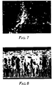
- Figure 7 is reproduced from a scanning electron photomicrograph showing a 5000 xs magnification of the top surface of a porous skin layer formed from a casting solution comprising 12 weight percent, based on total casting solution weight, of polyamide.
- Figure 8 is reproduced from a scanning electron photomicrograph showing a 350 xs magnification of a cross-sectional view of the porous membrane shown in Figure 7.
- asymmetric membranes of this invention have support layers comprising two or more regions or layers each of which comprises a three-dimensional network of substantially parallel, hollow tube-like structures oriented such that the longitudinal dimension of each tube-like structure is essentially perpendicular to the skin layer.
- each tube-like structure in a particular region of the support layer will have approximately the same cross-sectional area.
- the tube-like structures in adjacent support layer regions may have significantly different cross-sectional areas. This may result in the support layer appearing to be comprised of distinct, discontinuous regions or layers each comprising tube-like structures of approximately the same cross-sectional area.
- the support layer may appear to be comprised of tapered tube-like structures whose cross-sectional area increases with increasing distance from the skin layer.
- the polyamides useful in preparing the asymmetric membranes of this invention have glass transition temperatures below 200°C, preferably below 100°C, and most preferably below 60°C.
- the polyamides useful in this invention are aliphatic, that is, they can be selected from the group consisting of aliphatic polyamides, which includes cycloaliphatic polyamides. Blends of polyamides are also useful in this invention.
- each R group may be independently selected from the group consisting of H, and alkyl groups having 1 to 4 carbon atoms
- each R1, R2 and R3 group may be independently selected from the group consisting of linear or branched aliphatic or cycloaliphatic moieties or combinations thereof.
- all R1 groups will be the same and all R2 groups will be the same, and in any particular polymer (II), all R3 groups will be the same.
- R1, R2, and R3 groups will have from 1 to 12 carbon atoms, and preferably 1 to 10.
- R1, R2, and R3 groups can also contain hetero atoms such as oxygen, nitrogen, and sulfur.
- polyamides useful in this invention will have weight average molecular weights in excess of about 10,000 and can be prepared according to conventional methods such as those described in Kirk-Othmer Encyclopedia of Chemical Technology, 3rd Ed. , Vol. 18, John Wiley & Son 1982, pp. 350-353.
- Many of the polyamides useful in this invention are known and are commercially available, e.g., nylon 6,6 (i.e., poly(hexamethylene adipamide), nylon 6,9, and nylon 6 (i.e., polycaprolactam).
- nylon 6,6 i.e., poly(hexamethylene adipamide), nylon 6,9, and nylon 6 (i.e., polycaprolactam).
- Nylon 6,6 is commercially available from E.I. DuPont de Nemours Company as ZYTEL 101 or 120, described in DuPont brochure no.
- Nylon 6 is commercially available from Badische Corporation as B-300 and B-4407, and from Nylon Corporation of America as NYCOA 471, 466, and 589.
- Nylon 6,9 is commercially available from Aldrich Chemical Company and from Monsanto Corporation as VYDYNE 60H and 602M and Nylon 6,6/6 copolymer available from Monsanto Corporation as VYDYNE 80X.
- the casting solution used to make the asymmetric membranes of this invention is prepared by dissolving one or more of the polyamides described above in casting solvent.
- a casting solvent is a solution of salt dissolved in a lower (i.e., C1 to C4) alcohol or mixture of lower alcohols.
- the selection of alcohol, salt, and level of salt is largely determined by the solubility of the polyamide in the casting solvent.
- Representative examples of lower alcohols and lower alcohol mixtures useful in this invention are lower alkanols and mixtures of lower alkanols, e.g., methanol, ethanol, propanol, butanol, and ethanol/methanol, ethanol/propanol, and methanol/propanol mixtures.
- Methanol, ethanol, and mixtures containing at least 50 weight percent of methanol or ethanol are more preferred because a number of commonly available salts are soluble in them.
- the salt used to make the casting solution should increase the solubility of the polyamide in the alcohol.
- Representative salts include anyhdrous calcium chloride, calcium chloride dihydrate, calcium iodide tetrahydrate, calcium nitrate tetrahydrate, calcium salicylate and lithium chloride and blends thereof.
- calcium chloride dihydrate is used to make the casting solvent.
- the casting solution is a homogeneous solution at the time and temperature of casting the membrane. Preferably, it is a stable solution, i.e., does not phase separate upon standing at room temperature.
- the casting solution should also have a viscosity low enough to permit stirring and coating of the solution on a casting substrate or on a preformed membrane support.
- the solution viscosity will depend to some extent on the type, molecular weight, and concentration of polyamide used to make the solution. For example, a particular casting solution containing 8 weight percent of nylon 6,6 will have a viscosity of about 5000 cp at room temperature while a 5 weight percent solution will have a viscosity of about 1200 cp at room temperature. Casting solution viscosities below about 500 cp at room temperature are generally not preferred.
- the casting solution contains 10 to 50 weight percent of salt, based on total casting solution weight, and preferably 35 weight percent.
- the alcohol generally comprises 47 to 76 weight percent of the casting solution, based on total casting solution weight, and preferably about 60 weight percent.
- the casting solution comprises 3 to 14 weight percent of polyamide, based on the total weight of the casting solution.
- the optimum polyamide concentration depends on the molecular weight of the polymer and evaporation time used. However, the desired polyamide must be soluble at a level of at least 3 weight percent because concentrations of less than 3 weight percent will not result in the formation of a membrane having the desired structure.
- a preferred casting solution can be prepared by mixing 35 parts by weight of calcium chloride dihydrate with 65 parts by weight of methanol, refluxing the mixture until the calcium chloride dihydrate has completely dissolved, mixing 4 to 7 parts by weight of nylon 6,6 with the salt/alcohol solution, and refluxing the resulting mixture until the nylon has completely dissolved.
- the casting solution can also contain non-interferring, conventional casting solution additives.
- the relative amounts and types of additives should be selected so as not to adversely affect final membrane structure.
- One such additive is non-ionic surfactant, e.g. TRITON-X 100 commercially available from Rohm & Haas Corporation or TWEEN 20 commercially available from ICI Americas, Incorporated. Blends of non-ionic surfactants may also be used.
- the casting solution will comprise less than 1 weight percent surfactant and more typically less than 0.5 weight percent.
- the casting solution may also comprise small amounts of pore formers, swelling agents, and plasticizers.
- the casting solution may further comprise non-solvent, e.g. water, or blends of non-solvents.
- the effect of added non-solvent on the final membrane structure is relatively small, but typically an increasing amount of non-solvent in the casting solution results in larger pores in the membrane's skin layer.
- the maximum amount of additives that can be added to the casting solution is limited by the solubility of the polyamide in the resulting solution and may depend on the salt concentration in the casting solution and the type of salt used in the casting solution. Generally, the higher the salt concentration the greater the amount of water that can be added to the casting solution. However, the maximum amount of water that can be added to the casting solution is reduced by any amount of water that was initially complexed to the salt. For example, the maximum amount of water that can be added to a casting solution comprising methanol and calcium chloride is about 0.8 g of water per 1 g of calcium chloride.
- the casting solution can be formed into a sheet or film by coating or depositing on the desired area of the exposed surface of a casting substrate the desired thickness of casting solution.
- the casting substrates useful in this invention include many of the substrates known in the art.
- the substrates include, glass, glass-coated materials, stainless steel, poly(ethylene terephthalate), polypropylene, poly(tetrafluoroethylene)-coated materials, and silicone coated paper or belts.
- Conventional casting methods and equipment may be used such as knife coaters, slot-fed knife coaters, and notch bar coaters.
- the casting solution may also be coated directly onto a porous, preformed support having two parallel surfaces to form one of the supported or composite membranes of this invention.
- Such preformed supports are non-woven fibrous webs, woven fabrics or paper.
- the casting solution is applied to one or both of the parallel surfaces. Casting the membrane on such a support can provide additional strength to the membrane.
- the preformed support must have a very porous or open structure so that it does not restrict the flow of fluids through the membrane. That is, the average pore size of the support should be at least as large as the biggest pore in the membrane.
- the preformed support should be made of a material which can be wet by the casting solution. Generally, a preformed support comprising polyamide material will be more easily wet by the casting solution.
- the casting solution can be extruded through an annular die.
- air or liquid in which the polyamide is insoluble can flow through the lumen of the fiber.
- the liquid need not be the same as the non-solvent used in the non-solvent bath. Conventional extrusion methods and equipment may be used to prepare hollow fiber membranes of this invention.
- the solution can be cast or extruded to a wet thickness 0.05 to 0.51 mm (0.002 to 0.020 in) thick. This generally will result in a dry membrane 0.025 to 0.25 mm (0.001 to 0.010 in) thick.
- the solution is cast to a wet thickness of 0.10 to 0.18 mm (0.004-0.007 in) which generally results in dry membranes between 0.051 to 0.152 mm (0.002 to 0.006 in) thick.
- the coated substrate may optionally be exposed to air for drying. Exposure to air can affect the thickness and porosity of the skin layer of the membrane. The longer the membrane is exposed to air, the less porous the skin layer of the membrane will be. Exposure times of up to 120 seconds may be used, however, an exposure time about 30 seconds or less, e.g. 5 to 15 seconds, is preferred.
- the still-wet membrane is exposed to a non-solvent, such as water or water vapor, to precipitate the polyamide to form the membrane.
- a non-solvent such as water or water vapor
- the preferred non-solvent comprises water or water and water vapor. Exposure to non-solvent only in the form of vapor does not yield membranes having applicants' characteristic membrane structure. Hence if non-solvent vapor is to be used to precipitate the polyamide, exposure to the vapor must be short, e.g., 10 min. or less, and such exposure must be followed by immersion of the membrane in a liquid non-solvent bath.
- the humidity in the chamber should be kept above about 50 percent relative humidity, and most preferably should be 90 to 100 percent relative humidity.
- immersion of the membrane in a liquid non-solvent bath is the preferred method of exposing the wet membrane to the non-solvent.
- liquid non-solvent baths useful in this invention comprise a major amount of water and a minor amount of a polar organic solvent.
- Suitable polar organic solvents include the lower (i.e. having one to four carbon atoms) alkanols, e.g. isopropanol, the lower ketones, e.g., acetone and methylethyl ketone, lower ethers, e.g., tetrahydrofuran, lower nitriles, e.g., acetonitrile, and lower amides, e.g., dimethyl formamide. Acetone is particularly preferred.
- As much as 20 to 25 volume percent of the total non-solvent bath may be polar organic solvent. However, preferably the bath will contain less than about 20 volume percent, and most preferably less than 15 volume percent of polar organic solvent.
- the liquid non-solvent bath is generally maintained at room temperature. Bath temperatures below room temperature tend to result in slower coagulation or precipitation rates.
- the coated casting substrate or extruded hollow fiber should be immersed in the bath and remain there for at least 1 minute or until the membrane begins to float off the casting substrate. The membrane may then be recovered from the bath and washed with water.
- a membrane may be dried after formation and recovery by any suitable means. Drying with forced, heated air hastens drying time but promotes wrinkling of the membrane if the membrane is not dimensionally secured during drying. A wet membrane allowed to dry under ambient conditions releases easily from polytetrafluoroethylene-coated substrate surfaces.
- the flux rate through the membranes of this invention can be varied by varying the percent porosity of the membrane (i.e., percent of the membrane volume comprising voids), the asymmetric ratio (i.e., the ratio is the average pore diameter on the bottom surface of the support layer divided by the average pore diameter of the skin layer), and/or the average pore diameter of the skin layer.
- the flux rate can also be varied by controlling the thickness of the membrane, and by using multiple thicknesses of membrane. For example, a single layer or thickness of some of the microfiltration membranes of this invention will have normalized air flux rates of 2.5 L/kPa(sec)m2 to 75 L/kPa(sec)m2, and will have bubble points of 0.5 to 20 »m.
- the average pore diameter of the skin layer of membranes of this invention is selected based on the desired application, i.e. ultrafiltration or microfiltration, of the membrane and can be controlled using the process variables described above.
- Some of the membranes of this invention have average skin layer pore diameters of 0.001 »m to 10 »m, and average pore diameters on the bottom surface of the support layer of 20 to 500 »m.
- the percent porosity of the membranes of this invention will be greater than 70 percent, and preferably greater than 80 percent.
- the asymmetric ratio must be greater than 1, and preferably is greater than 10, e.g., 10 to 100,000. Asymmetric ratios of 2000 or more have easily been achieved using the process of this invention.
- a nylon 6,6 membrane having a dry thickness of 0.25 mm may have an 87 percent flux decline at 345 kPa (as determined by the difference between the initial flux and the steady state flux at the measured pressure).
- a membrane having a 0.12 mm dry thickness may have a flux decline of 21 percent or less at 345 kPa, and a membrane having a 0.04 mm dry thickness may have a flux decline of 10 percent or less at 345 kPa.
- An amount (35 mL) of the casting solution was deposited onto a 35 cm x 50 cm glass plate and spread to a wet thickness of 254 »m to 305 »m using a glass plate with shims parallel to the edges of the plate.
- the casting plate was immediately immersed in a non-solvent bath consisting of 1900 mL of water and 100 mL of acetone held at 22-24°C. The plate remained immersed in the bath for about 1 minute after which the membrane was removed from the bath, blotted with paper towels, and was laid on a TEFLON-coated sheet and allowed to dry, skin side up, at ambient temperature for about 3 hours.
- the dry thickness of the membrane was about 51 to 64»m.
- Bubble points and normalized air flow rates were measured on the membrane. Both tests were performed on 47 mm diameter disks die-punched from a pinhole-free area of the membrane.
- the air flow rate measurements were carried out using an apparatus having a membrane sample mounted in a 47 mm diameter, stainless steel filter holder from Fischer Scientific, Inc. The membrane sample was mounted such that the skin layer faced upstream. Nitrogen gas was applied to the upstream side of the membrane until a standard flow rate of 14.85 standard liters/min. was measured on a rotameter located on the downstream side of the membrane. When this flow rate was achieved, the pressure drop across the membrane was measured using an Ashcroft "brazed" pressure gauge. The air flow rate measurement provides an indication of the resistance of the membrane to the transport of fluids through the membrane. The normalized air flow rate was then calculated using the following formula: where the pressure drop is in kPa and the filter area is in m2. The membrane was found to have normalized air flow of 8.34 L/kPa(sec)(m2).
- the bubble point was determined using an apparatus similar to that used to measure the air flow rate.
- the bubble point was measured on a sample of the membrane throughly wet with LUBINOL mineral oil (having a mathematical constant of 14.4 which is commercially availiable from Kalipharmo, Inc.) mounted in the filter holder such that the skin side of the membrane faced upstream.
- a tube extended from the downstream side of the filter holder into a reservoir filled with soapy water.
- the pressure on the upstream side of the membrane was then increased by slowly increasing the flow of nitrogen gas to the upstream side of the membrane until bubbles first appeared in the soapy water.
- the pressure at which bubbles first appeared was identified as the bubble point.
- the membrane had a bubble point of 0.87 »m.
- the membrane was also subjected to a latex particle challenge test.
- the challenge test was performed using an aqueous solution of Dow polystyrene particles having a mean diameter of 0.22»m.
- the solutions of latex particles had an absorbance of about 0.190-0.200 (measured using a Beckman Model 35 spectrophotometer using a visible light source at a wave length of 420 nm).
- a pinhole-free sample of membrane was mounted in an AMICON Model 12, 25 mm filter assembly operated in a straight filtration, no recirculation mode.
- Each of the latex particle solutions was filtered through the membrane.
- the filtrate or permeate passing though the membrane was collected and its absorbance was measured using the same spectrophotometer and light source described above.
- the percent of particles retained by the membrane was then calculated using the following fomula: The membrane retained 99.5 percent of latex particles having a mean diameter of 0.22 »m illustrating the membrane's usefulness for microfiltration processes.
- Scanning electron photomicrographs of this membrane revealed that the membrane possessed the characteristic structure of the membranes of this invention. Scanning electron photomicrographs were also used to estimate the average pore diameters. Photomicrographs showed that the average pore diameter of the skin layer of the membrane was about 0.1 »m and that the average pore diameter on the bottom surface of the support layer was about 100 to 200 »m. Thus, the membrane had an asymmetric ratio of about 1000:1 to about 2000:1.
- Example 1 The procedure described in Example 1 was repeated except that the casting solution contained 5.5 weight percent of a Nylon 6 (commercially available as NYCOA 471), and the acetone concentration in the non-solvent bath was either 5 or 15 weight percent. Air flow rate measurements were carried out according to the procedure described in Example 1. The membranes had normalized air flow rates of 36.2 and 145 L/kPa(sec)(m2), respectively.
- Example 1 The procedure described in Example 1 was repeated except that various types and amounts of the polar organic solvent used in the non-solvent bath were used. Air flow rates and bubble points were determined using the procedures described in Example 1. The types and amounts of polar organic solvent, and the properties of the resulting asymmetric membranes are summarized in Table 1.
- Example 1 The procedure of Example 1 was repeated except that a 5 weight percent solution of a nylon 6 commercially available as NYCOA 471 was used as the casting solution in Example 15, and 4.5 weight percent solution of the nylon 6 was used in Example 16.
- a double thickness of each of the membranes of Examples 15 and 16, respectively were tested. The membranes were arranged so that their skin layers were in a face-to-face orientation. The normalized air flow rates and bubble points of the resulting asymmetric membranes and their double thicknesses were measured according to the procedures described in Example 1. The membranes used, number of thicknesses, normalized air flow rates, and bubble points are summarized in Table 2.
- the data shows that while doubling the thickness of the membrane reduces the bubble point of the membrane, it also reduces the normalized air flow rate. This illustrates that a membrane of this invention can be sandwiched or layered to vary the flow rates and bubble point of the final membrane.
- Example 2 The procedure of Example 1 was repeated except that the coated casting substrate was immersed in a 95:5 volumetric mixture of water and methyl ethyl ketone.
- the resulting membrane was 51 »m thick and had normalized air flow of 145 L/kPa(sec)m2 and a bubble point of 5 »m.
- a double thickness of this membrane had a normalized flow of 75 L/kPa(sec)m2 and a bubble point of about 2.5 »m.
- a triple sandwich has a normalized flow rate of greater than about 36 L/kPa(sec)m2 and a bubble point of 1.2 »m. This illustrates that a membrane of this invention can be sandwiched or layered to vary the flow rates and bubble point of the final membrane.
- This example illustrates the use of a mixture of polyamides to form one of the membranes of this invention.
- a 5.0 weight percent polyamide casting solution was prepared using a 50/50 weight percent mixture of nylon 6 (commercially available as NYCOA 589) and nylon 6,6, (commercially available as CELANESE 1200-1) and a 37 weight percent calcium chloride dihydrate solution in methanol. The resulting mixture was refluxed about 12 hours to yield a generally clear and stable solution.
- This casting solution was then spread on a polyethylene terephthalate (i.e., PET) casting substrate using 10.2 cm Gardner knife coater set at a clearance of 0.25 mm.
- the coated casting substrate was then exposed to ambient air for about 15 seconds, and immersed in a non-solvent bath of deionized water.
- the coated casting substrate remained immersed in the bath for about 1 to 2 minutes until the membrane began to separate from the casting substrate.
- the membrane was recovered from the bath, blotted dry with paper towels, placed on paper towels, skin side up, and allowed to dry at room temperature for about 12 hours.
- Example 18 The procedure described in Example 18 was repeated except that only the nylon 6,6 was used to prepare the casting solution instead of the nylon 6 and nylon 6,6 blend and about 16 mg of TRITON-X 100 was added to about 5 g of the casting solution and the mixture was agitated. The resulting mixture was then deposited on a PET casting substrate and spread according the procedure described in Example 18. Scanning electron photomicrographs of the cross-sections of resulting membrane indicated that the membrane possessed the asymmetric structure characteristic of the membranes of the this invention.
- This example illustrates the preparation of one of the supported membranes of this invention.
- a casting solution was prepared according to the procedure of Example 18 except that the 5 weight percent casting solution was prepared using only the nylon 6,6 described in Example 18.
- the casting solution was then deposited on one surface of a nylon 6,6, spun-bonded, non-woven web (commercially available from the James River Corporation as CEREX).
- the coated, non-woven support was then placed on a PET casting substrate coated side up.
- the coated non-woven support (still resting on the casting substrate) was then exposed to ambient air for about 15 seconds, and immersed in a non-solvent bath of water.
- the coated support and casting substrate remained immersed in the bath for about 1 to 2 minutes after which time, the coated non-woven support was recovered from the bath, blotted dry with paper towels and was allowed to air dry, skin side up, at ambient temperature for about 12 hours.
- a membrane was prepared using a 5 weight percent, nylon 6,6 (Celanese 1200-1) casting solution prepared using a 37 weight percent calcium chloride dihydrate and methanol solution.
- the casting solution was spread on a polyethylene terephthalate casting substrate using a notch bar coater set at a gap of about 0.18 mm.
- the cast film was exposed to ambient air for about 30 seconds and then immersed in a large non-solvent water bath.
- the membrane remained immersed in the bath for about 1 to 2 minutes and was then recovered, blotted dry with paper towels, and allowed to dry at room temperature for about 12 hours.
- the resulting dried membrane was about 0.06 mm thick and scanning electron microscopy revealed that the membrane had skin layer pores of 0.5 »m or less, and pore diameters on the bottom surface of the support layer of 20 to 50 »m.
- the water flow rate through this membrane was measured using a 47 mm diameter sample of the membrane die cut from a pinhole-free section of the membrane.
- the membrane sample was mounted in an apparatus having a 47 mm diameter, stainless steel, Fisher Scientific filter holder such that the skin side of the membrane faced upstream.
- Water pressure was applied to the upstream side from a pressurized reservoir and the flow of water through the membrane measured with a rotameter located downstream from the membrane. The pressure was held at 345 kPa (50 psig) until water flow through the membrane became constant, at which point, the pressure was decreased in 34.5 kPa (5 psig) increments and the flow rate measured at each pressure.
- the water flow rate was also measured on a nylon 6,6 membrane having a 0.22 »m rating (commercially available from MSI Corporation as MAGNA membranes). Scanning electron microscopy revealed that the MSI membrane had surface pores on both surfaces of 2 »m or less. The water flow rate for Applicants' membrane was consistently about an order of magnitude greater than that achieved by the MSI membrane over a pressure range of 34.5 to 207 kPa.
- a membrane was cast from a 12 weight percent, nylon 6,6 (commercially available as Celanese 1200-1) solution using the procedure described in Example 18. except that the cast film was exposed to air for about 30 seconds.
- the solute rejection coefficient of the resulting membrane was measured using a 0.5 wt. % solution of blue dextran (approximately 2,000,000 MW, available from Sigma Chemical Corporation) having an absorbance of 1.30 at 260 nm, measured using a Hewlett-Packard 8451A Diode Array Spectrophotometer. Ultrafiltration measurements were made on the membrane using a 25 mm Amicon Stirred Ultrafiltration Cell. The permeate volume removed during the experiment was sufficiently small relative to the feed volume that the feed concentration did not appreciably change during the experiment.
- rejection coefficient 1-C p /C f where C f is the concentration of dextran in the feed solution and C p is the concentration of dextran in the permeate. At a transmembrane pressure of 276 kPa, the rejection coefficient was 0.95. This indicates that the membrane functioned as an ultrafiltration membrane.
- Example 18 The procedure of Example 18 was repeated except that (a) a 35 weight percent solution of calcium chloride dihydrate dissolved in methanol was used to prepare a 5.0 weight percent, nylon 6,6 (available from Celanese as 1200-1) casting solution, and (b) various air exposure times were used.
- the resulting membranes were studied using scanning electron microscopy. Photomicrographs were used to estimate the average pore diameters in the skin layer and on the bottom surface of the support layer. Photomicrographs of cross-sections of the membrane indicated that all of the membranes possessed the asymmetric structure characteristic of the membranes of the invention.
- Air flow measurements were also made on the membranes. Air flow rate measurements were made using 25 mm disks cut from a pinhole-free area of the membranes. Membrane samples were mounted in a 25 mm Swinnex filter holder such that the skin layers faced upstream. Nitrogen gas was applied to the upstream side of the membranes at a pressure of 69 kPa (10 psig) and the flow of nitrogen through the membranes was measured using a rotameter located downstream from the filter holder.
- the data shows that the greater the air exposure time the lower the air flow rate will be. This may be because the skin layer is less porous.
- Example 27 The procedure of Example 27 was repeated except that the membranes were cast to various thicknesses. The resulting membranes were studied using scanning electron microscopy. Photomicrographs of cross-sections of the membranes indicated that all of the membranes possessed the characteristic asymmetric structure of the membranes of this invention. Photomicrographs were used to determine the average pore diameter in the skin layer and the average pore diameter on the bottom surface of the membrane's support layer. Air flow rates were measured for each membrane using the procedure described in Examples 24-29.
- Knife Clearance (mm) Average pore dia. (»m) Air Flow [L/(sec)m2] Skin layer Bot. surface 30 0.13 ⁇ 0.5 10-20 290 31 0.38 ⁇ 0.5 100-300 272 32 0.51 ⁇ 0.5 200-500 210
- the data shows that the cast thickness affects the pore diameter on the bottom surface of the support layer.
- the air flow rate may be decreasing because the thickness of the skin layer increased as membrane thickness increased.
- Example 18 The procedure of Example 18 was repeated except that in Examples 33 and 34 a 36 weight percent solution of calcium chloride dihydrate in methanol was used to prepare a 3 weight percent casting solution of nylon 6,6 (Celanese 1200-1), and in Examples 35-37 the calcium chloride/methanol dihydrate solution described above was used to prepare a 4 weight percent casting solution of the nylon 6,6.
- various air exposure times were used.
- the resulting membranes were studied using scanning electron microscopy. The air exposure times, membrane structures, and average pore diameters are summarized below in Table 5.
- Table 5 Ex. Exposure time (sec) Average pore dia. (»m) Charact. structure Skin layer Bot. surface 33 30 ⁇ 0.1 100 yes 34 15 ⁇ 0.5 50-100 no 35 0 1.0 100 yes 36 15 1.0 20-50 yes 37 30 1.0 100 yes
- the data shows that at the 3 weight percent level of polyamide, and air exposure time can affect whether the membrane will have the characteristic asymmetric structure of the membranes of this invention. However, at the 4 weight percent level of polyamide, the exposure time did not affect whether the membrane had the characteristic asymmetric structure.
- Example 18 The procedure of Example 18 was repeated except that various polyamides were used instead of the NYCOA 589/CELANESE 1200-1 blend. The membranes were studied using scanning electron microscopy. The polyamides used, average pore diameters and membrane structures of the resulting membranes are summarized in Table 6. Table 6 Ex. Polyamide Average pore dia.(»m) Charact. structure Skin layer Bot. surface 38 Nylon 6,6 (ZYTEL 101) 0.2-3 20-50 yes 39 Nylon 6 (Nycoa 466) 0.5-5 50-100 yes 40 Nylon 6 (Nycoa 589) ⁇ 0.1 50-100 yes 41 Nylon 6,9 (Aldrich Chemical) ⁇ 0.1 30-50 yes
- Example 18 The procedure of Example 18 was repeated except that various salts and salt concentrations were used instead of the 37 wt. % solution of calcium chloride dihydrate and CELANESE 1200-1 alone instead of the nylon blend. The resulting membranes were studied using scanning electron microscopy. The salts used, percent concentration of the salt, average pore diameter and membrane structures are summarized in Table 7. Table 7 Ex. Salt structure Conc. Salt(%) Average pore dia. (»m) Charact. Skin layer Bot. surface 42 CaCl2 29 ⁇ 1.0 50 yes 43 Ca(NO3)2 ⁇ 4H20 46 ⁇ 1.0 20-50 yes 44 Calcium Salicylate 53 1.0 0.5-5 yes 45 CaCl2 ⁇ 4H2O 56 ⁇ 0.5 10-20 yes 46 LiCl 24 1.0 100 yes
- Example 18 The procedure of Example 18 was repeated except that various blends of isopropanol and methanol were used instead of methanol to prepare the casting solution and an air exposure time of 5 seconds was used and CELANESE 1200-1 alone was used instead of the nylon blend.
- blends of isopropanol and methanol can be used to prepare the casting solution.
- blends containing more than 50 volume percent isopropanol would not dissolve the polyamide.
Landscapes
- Chemical & Material Sciences (AREA)
- Chemical Kinetics & Catalysis (AREA)
- Separation Using Semi-Permeable Membranes (AREA)
- Manufacture Of Porous Articles, And Recovery And Treatment Of Waste Products (AREA)
Description
- This invention relates to porous asymmetric polyamide membranes useful in microfiltration and ultrafiltration.
- CA-A-1,168,006 (Wrasidlo) discloses an asymmetric ultrafiltration membrane having a skin layer supported by an "open honeycomb structure". The specification states that only polymeric materials having glass transition temperatures of at least 200°C would be suitable in the invention since only polymers having such relatively high glass transition temperatures are sufficiently rigid to form the honeycomb support structure. Of the polyamides, only polyarylamides were specifically identified as useful. The specification also states that the skin layer of the membranes has slit-like fissures instead of substantially circular pores.
- US-A-4,629,563 (Wrasidlo) discloses asymmetric membranes which may be used as ultrafilters or microfilters. The membranes can have a skin layer and a porous, asymmetric, reticulated support layer. The membranes described in the '563 patent can be made of polyamide, however, only polyhexamethylene terephthalamide, an araliphatic polyamide, is specifically disclosed. The membranes are formed by casting a polymer dope while that dope is in an unstable liquid dispersion condition.
- US-A-4,627,992 (Badenhop et al.) describes membranes formed from aromatic polyamide resins. The membranes described in the '992 patent can be symmetric or asymmetric and can be produced using a solution of the polyamide in an aprotic solvent.
- US-A-4,340,481 (Mishiro et al) describes a hollow fiber membrane having a three-dimensional net-like structure of fine pore passages. In Example 8, one such hollow fiber membrane is prepared from a casting solution containing 18 weight percent polyamide, methyl alcohol, water and calcium chloride dihydrate using a 1:1 methanol/water coagulation bath.
- US-A-4,722,795 (Gohl et al.) describes asymmetric, self-supporting membranes, useful for ultrafiltration, which may be in the form of a flat sheet, tube, or hollow fiber. The patent states that suitable membrane materials are polymers which are soluble in polar, non-protonic organic solvents such as dimethylsulfoxide. While the patent states that polyamides are preferred for use in forming the membranes, only an aromatic polyamide is specifically disclosed.
- US-A-3,876,738 (Marinaccio et al.) describes a process for making microporous membranes in which a film-forming polymer, e.g. nylon, is dissolved in a solvent system, e.g., a formic acid solution, the resulting solution is cast to form a film, and the film is quenched in a non-solvent bath, e.g. water/salt or alcohol/salt solutions, to form a microporous membrane. This patent does not state that these membranes are asymmetric.
- US-A-4,482,514 (Schindler et al.) describes a process for preparing ultrafiltration membranes using a formic acid solution of polyamide containing about 1 to 7 % polyethylene glycol. The patent states that the membrane possesses an ultrafiltration skin layer and a backing layer in which the pore size increases with the distance from the ultrafiltration skin. Figure 2 of the patent depicts a cross-sectional view of a membrane having a gradually increasing pore size.
- JP-A-58094863, laid open June 6, 1983, describes polyamide membranes having a rough surface and a smooth surface. It describes the process of preparing one such membrane which includes preparation of a 10 to 40 weight percent solution of nylon 6,6 dissolved in formic acid mixed with calcium chloride and water, casting of the resulting solution, and intermittent coagulation, e.g. by repeated dipping of the cast membrane in a coagulation bath, of the cast film to form an uneven surface. The disclosed pore sizes range from 0.05 to 500 »m on the rough surface and 1 to 1000 »m on the smooth surface.
- US-A-3,615,024 (Michaels) describes anisotropic membranes which can be formed from polyamides such as polyhexamethylene adipamide and other such polyamides known as "nylon", however, no such membranes are exemplified.
- US-A-4,340,480 and 4,340,479 (Pall et al.) disclose a process for preparing skinless liquofilic alcohol-insoluble polyamide microfiltration membranes from polyamide having a ratio of methylene to amide groups of about 7 to 1 to about 12 to 1. The patents disclose that membranes prepared according to the described process have pores of uniform diameter. The patents also state that their membranes can have "tapering pores" but they do not describe highly asymmetric membranes.
- This invention provides an asymmetric, porous polyamide membrane permeable to fluid flow comprising:
- (A) a porous skin layer, and
- (B) adjacent to the skin layer, an integral, porous support layer (i.e., a support layer formed in the same operation or step and having substantially the same composition as the skin layer) having at least one region comprising a network of substantially parallel, hollow tube-like structures, each of the tube-like structures being oriented such that the longitudinal dimension of each tube-like structure is essentially perpendicular to the skin layer;
wherein:
the skin layer is relatively thin and dense compared to the support layer,
the pore diameters in the skin layer are relatively small compared to the diameters of the tube-like structures in the support layer, and
in membranes having support layers with more than one region, the cross-sectional area of the tube-like structures is larger in regions located farther from the skin layer, and
the polyamide is an aliphatic polyamide having a glass transition temperature of less than 200°C. - This invention further provides supported asymmetric membranes, i.e., membranes comprising the polyamide membrane described above and a preformed, porous, support layer, e.g. non-woven web, woven cloth or paper, having two parallel surfaces.
- This invention also provides a method of preparing the asymmetric and supported asymmetric membranes described above comprising the steps of:
- a) preparing a casting solution comprising the polyamide dissolved in an alcohol/salt solution;
- b) coating a film of preselected thickness of the casting solution onto the surface of a casting substrate (e.g. a TEFLON-coated surface, glass, or polyethylene terephthalate) or coating a film of preselected thickness of the casting solution onto one or both of the parallel surfaces of a preformed, porous support material and placing the resulting coated preformed support on a casting substrate, or
- c) extruding a hollow fiber of the casting solution through an annular die;
- d) immersing the resulting film, coated preformed support, or hollow fiber in a liquid non-solvent bath thereby precipitating the polyamide and forming an asymmetric polyamide membrane or asymmetric, supported polyamide membrane, and
recovering the membrane or supported membrane from the non-solvent bath and drying it. - The membranes of this invention can be useful in microfiltration or ultrafiltration separation processes depending upon the pore size of the porous skin layer.
- Figure 1 is reproduced from a scanning electron photomicrograph showing a 420 xs magnification of a cross-sectional view of one of applicants' membranes. This membrane was formed from a casting solution comprising 5 weight percent, based on total casting solution weight, of polyamide.
- Figure 2 is reproduced from a scanning electron photomicrograph showing a 11,700 xs magnification of the top surface of the porous skin layer of the membrane shown in Figure 1.
- Figure 3 is reproduced from a scanning electron photomicrograph showing a 116 xs magnification of the bottom surface of the porous support layer of the membrane shown in Figure 1.
- Figure 4 is reproduced from a scanning electron photomicrograph showing a 590 xs magnification of the bottom surface of the porous support layer of the membrane shown in Figure 3.
- Figure 5 is reproduced from a scanning electron photomicrograph showing a 3500 xs magnification of the top surface of a porous skin layer formed from a casting solution comprising 9 weight percent, based on total casting solution weight, of polyamide.
- Figure 6 is reproduced from a scanning electron photomicrograph showing a 250 xs magnification of a cross-sectional view of the membrane shown in Figure 5.
- Figure 7 is reproduced from a scanning electron photomicrograph showing a 5000 xs magnification of the top surface of a porous skin layer formed from a casting solution comprising 12 weight percent, based on total casting solution weight, of polyamide.
- Figure 8 is reproduced from a scanning electron photomicrograph showing a 350 xs magnification of a cross-sectional view of the porous membrane shown in Figure 7.
- Some of the asymmetric membranes of this invention have support layers comprising two or more regions or layers each of which comprises a three-dimensional network of substantially parallel, hollow tube-like structures oriented such that the longitudinal dimension of each tube-like structure is essentially perpendicular to the skin layer. Generally, each tube-like structure in a particular region of the support layer will have approximately the same cross-sectional area. However, the tube-like structures in adjacent support layer regions may have significantly different cross-sectional areas. This may result in the support layer appearing to be comprised of distinct, discontinuous regions or layers each comprising tube-like structures of approximately the same cross-sectional area. When adjacent regions are comprised of tube-like structures having similar cross-sectional areas, the support layer may appear to be comprised of tapered tube-like structures whose cross-sectional area increases with increasing distance from the skin layer.
- The polyamides useful in preparing the asymmetric membranes of this invention have glass transition temperatures below 200°C, preferably below 100°C, and most preferably below 60°C. The polyamides useful in this invention are aliphatic, that is, they can be selected from the group consisting of aliphatic polyamides, which includes cycloaliphatic polyamides. Blends of polyamides are also useful in this invention.
- Some classes of the polyamides useful in this invention can be represented by the following general formulas:

wherein each R group may be independently selected from the group consisting of H, and alkyl groups having 1 to 4 carbon atoms, and each R¹, R² and R³ group may be independently selected from the group consisting of linear or branched aliphatic or cycloaliphatic moieties or combinations thereof. Generally in any particular polymer (I), all R¹ groups will be the same and all R² groups will be the same, and in any particular polymer (II), all R³ groups will be the same. Generally R¹, R², and R³ groups will have from 1 to 12 carbon atoms, and preferably 1 to 10. R¹, R², and R³ groups can also contain hetero atoms such as oxygen, nitrogen, and sulfur. - Generally the polyamides useful in this invention will have weight average molecular weights in excess of about 10,000 and can be prepared according to conventional methods such as those described in Kirk-Othmer Encyclopedia of Chemical Technology, 3rd Ed., Vol. 18, John Wiley & Son 1982, pp. 350-353. Many of the polyamides useful in this invention are known and are commercially available, e.g., nylon 6,6 (i.e., poly(hexamethylene adipamide), nylon 6,9, and nylon 6 (i.e., polycaprolactam). Nylon 6,6 is commercially available from E.I. DuPont de Nemours Company as ZYTEL 101 or 120, described in DuPont brochure no. E-26345, from Monsanto Corporation as VYDYNE 21, described in Monsanto brochure no. 8-1117-0880-92, and from Celanese Corporation as 1001-1 or 1200-1, described in Celanese "Bulletin N1A" brochure no. 10M/583-5M85. Nylon 6 is commercially available from Badische Corporation as B-300 and B-4407, and from Nylon Corporation of America as NYCOA 471, 466, and 589. Nylon 6,9 is commercially available from Aldrich Chemical Company and from Monsanto Corporation as VYDYNE 60H and 602M and Nylon 6,6/6 copolymer available from Monsanto Corporation as VYDYNE 80X.
- The casting solution used to make the asymmetric membranes of this invention is prepared by dissolving one or more of the polyamides described above in casting solvent. A casting solvent is a solution of salt dissolved in a lower (i.e., C1 to C4) alcohol or mixture of lower alcohols. The selection of alcohol, salt, and level of salt is largely determined by the solubility of the polyamide in the casting solvent. Representative examples of lower alcohols and lower alcohol mixtures useful in this invention are lower alkanols and mixtures of lower alkanols, e.g., methanol, ethanol, propanol, butanol, and ethanol/methanol, ethanol/propanol, and methanol/propanol mixtures. Methanol, ethanol, and mixtures containing at least 50 weight percent of methanol or ethanol are more preferred because a number of commonly available salts are soluble in them. The salt used to make the casting solution should increase the solubility of the polyamide in the alcohol. Representative salts include anyhdrous calcium chloride, calcium chloride dihydrate, calcium iodide tetrahydrate, calcium nitrate tetrahydrate, calcium salicylate and lithium chloride and blends thereof. Preferably calcium chloride dihydrate is used to make the casting solvent.
- The casting solution is a homogeneous solution at the time and temperature of casting the membrane. Preferably, it is a stable solution, i.e., does not phase separate upon standing at room temperature. The casting solution should also have a viscosity low enough to permit stirring and coating of the solution on a casting substrate or on a preformed membrane support. The solution viscosity will depend to some extent on the type, molecular weight, and concentration of polyamide used to make the solution. For example, a particular casting solution containing 8 weight percent of nylon 6,6 will have a viscosity of about 5000 cp at room temperature while a 5 weight percent solution will have a viscosity of about 1200 cp at room temperature. Casting solution viscosities below about 500 cp at room temperature are generally not preferred.
- Typically the casting solution contains 10 to 50 weight percent of salt, based on total casting solution weight, and preferably 35 weight percent. The alcohol generally comprises 47 to 76 weight percent of the casting solution, based on total casting solution weight, and preferably about 60 weight percent. Generally the casting solution comprises 3 to 14 weight percent of polyamide, based on the total weight of the casting solution. The optimum polyamide concentration depends on the molecular weight of the polymer and evaporation time used. However, the desired polyamide must be soluble at a level of at least 3 weight percent because concentrations of less than 3 weight percent will not result in the formation of a membrane having the desired structure.
- A preferred casting solution can be prepared by mixing 35 parts by weight of calcium chloride dihydrate with 65 parts by weight of methanol, refluxing the mixture until the calcium chloride dihydrate has completely dissolved, mixing 4 to 7 parts by weight of nylon 6,6 with the salt/alcohol solution, and refluxing the resulting mixture until the nylon has completely dissolved.
- Optionally, the casting solution can also contain non-interferring, conventional casting solution additives. The relative amounts and types of additives should be selected so as not to adversely affect final membrane structure. One such additive is non-ionic surfactant, e.g. TRITON-X 100 commercially available from Rohm & Haas Corporation or TWEEN 20 commercially available from ICI Americas, Incorporated. Blends of non-ionic surfactants may also be used. Generally the casting solution will comprise less than 1 weight percent surfactant and more typically less than 0.5 weight percent. The casting solution may also comprise small amounts of pore formers, swelling agents, and plasticizers. The casting solution may further comprise non-solvent, e.g. water, or blends of non-solvents. Generally, the effect of added non-solvent on the final membrane structure is relatively small, but typically an increasing amount of non-solvent in the casting solution results in larger pores in the membrane's skin layer. The maximum amount of additives that can be added to the casting solution is limited by the solubility of the polyamide in the resulting solution and may depend on the salt concentration in the casting solution and the type of salt used in the casting solution. Generally, the higher the salt concentration the greater the amount of water that can be added to the casting solution. However, the maximum amount of water that can be added to the casting solution is reduced by any amount of water that was initially complexed to the salt. For example, the maximum amount of water that can be added to a casting solution comprising methanol and calcium chloride is about 0.8 g of water per 1 g of calcium chloride.
- The casting solution can be formed into a sheet or film by coating or depositing on the desired area of the exposed surface of a casting substrate the desired thickness of casting solution. The casting substrates useful in this invention include many of the substrates known in the art. For example, the substrates include, glass, glass-coated materials, stainless steel, poly(ethylene terephthalate), polypropylene, poly(tetrafluoroethylene)-coated materials, and silicone coated paper or belts. Conventional casting methods and equipment may be used such as knife coaters, slot-fed knife coaters, and notch bar coaters. The casting solution may also be coated directly onto a porous, preformed support having two parallel surfaces to form one of the supported or composite membranes of this invention. Representative examples of such preformed supports are non-woven fibrous webs, woven fabrics or paper. The casting solution is applied to one or both of the parallel surfaces. Casting the membrane on such a support can provide additional strength to the membrane. The preformed support must have a very porous or open structure so that it does not restrict the flow of fluids through the membrane. That is, the average pore size of the support should be at least as large as the biggest pore in the membrane. In order to facilitate the formation of the membrane and reduce the number of pinholes in the membrane, the preformed support should be made of a material which can be wet by the casting solution. Generally, a preformed support comprising polyamide material will be more easily wet by the casting solution.
- When a hollow fiber membrane is desired, the casting solution can be extruded through an annular die. Optionally, air or liquid in which the polyamide is insoluble can flow through the lumen of the fiber. The liquid need not be the same as the non-solvent used in the non-solvent bath. Conventional extrusion methods and equipment may be used to prepare hollow fiber membranes of this invention.
- The solution can be cast or extruded to a wet thickness 0.05 to 0.51 mm (0.002 to 0.020 in) thick. This generally will result in a dry membrane 0.025 to 0.25 mm (0.001 to 0.010 in) thick. Preferably, the solution is cast to a wet thickness of 0.10 to 0.18 mm (0.004-0.007 in) which generally results in dry membranes between 0.051 to 0.152 mm (0.002 to 0.006 in) thick.
- After depositing the casting solution on the substrate, the coated substrate may optionally be exposed to air for drying. Exposure to air can affect the thickness and porosity of the skin layer of the membrane. The longer the membrane is exposed to air, the less porous the skin layer of the membrane will be. Exposure times of up to 120 seconds may be used, however, an exposure time about 30 seconds or less, e.g. 5 to 15 seconds, is preferred.
- After the optional drying step described above, the still-wet membrane is exposed to a non-solvent, such as water or water vapor, to precipitate the polyamide to form the membrane. The preferred non-solvent comprises water or water and water vapor. Exposure to non-solvent only in the form of vapor does not yield membranes having applicants' characteristic membrane structure. Hence if non-solvent vapor is to be used to precipitate the polyamide, exposure to the vapor must be short, e.g., 10 min. or less, and such exposure must be followed by immersion of the membrane in a liquid non-solvent bath. When water vapor is used as one of the non-solvents, the humidity in the chamber should be kept above about 50 percent relative humidity, and most preferably should be 90 to 100 percent relative humidity. However, since it is simpler to use only one precipitation step, immersion of the membrane in a liquid non-solvent bath is the preferred method of exposing the wet membrane to the non-solvent.
- Some of the liquid non-solvent baths useful in this invention comprise a major amount of water and a minor amount of a polar organic solvent. Suitable polar organic solvents include the lower (i.e. having one to four carbon atoms) alkanols, e.g. isopropanol, the lower ketones, e.g., acetone and methylethyl ketone, lower ethers, e.g., tetrahydrofuran, lower nitriles, e.g., acetonitrile, and lower amides, e.g., dimethyl formamide. Acetone is particularly preferred. As much as 20 to 25 volume percent of the total non-solvent bath may be polar organic solvent. However, preferably the bath will contain less than about 20 volume percent, and most preferably less than 15 volume percent of polar organic solvent.
- The liquid non-solvent bath is generally maintained at room temperature. Bath temperatures below room temperature tend to result in slower coagulation or precipitation rates. The coated casting substrate or extruded hollow fiber should be immersed in the bath and remain there for at least 1 minute or until the membrane begins to float off the casting substrate. The membrane may then be recovered from the bath and washed with water.
- A membrane may be dried after formation and recovery by any suitable means. Drying with forced, heated air hastens drying time but promotes wrinkling of the membrane if the membrane is not dimensionally secured during drying. A wet membrane allowed to dry under ambient conditions releases easily from polytetrafluoroethylene-coated substrate surfaces.
- The flux rate through the membranes of this invention can be varied by varying the percent porosity of the membrane (i.e., percent of the membrane volume comprising voids), the asymmetric ratio (i.e., the ratio is the average pore diameter on the bottom surface of the support layer divided by the average pore diameter of the skin layer), and/or the average pore diameter of the skin layer. The flux rate can also be varied by controlling the thickness of the membrane, and by using multiple thicknesses of membrane. For example, a single layer or thickness of some of the microfiltration membranes of this invention will have normalized air flux rates of 2.5 L/kPa(sec)m² to 75 L/kPa(sec)m², and will have bubble points of 0.5 to 20 »m.
- The process variables having the greatest impact on the percent porosity of the membrane, asymmetric ratio, and average pore diameter of the retentive layer are:
- 1) the concentration of the polyamide in the casting solution,
- 2) the concentration of non-solvent in the liquid non-solvent bath, and
- 3) the time the membrane is exposed to air between the casting and precipitation steps.
- The average pore diameter of the skin layer of membranes of this invention is selected based on the desired application, i.e. ultrafiltration or microfiltration, of the membrane and can be controlled using the process variables described above. Some of the membranes of this invention have average skin layer pore diameters of 0.001 »m to 10 »m, and average pore diameters on the bottom surface of the support layer of 20 to 500 »m. Typically, the percent porosity of the membranes of this invention will be greater than 70 percent, and preferably greater than 80 percent. The asymmetric ratio must be greater than 1, and preferably is greater than 10, e.g., 10 to 100,000. Asymmetric ratios of 2000 or more have easily been achieved using the process of this invention. Large asymmetric ratios are desirable since a high degree of membrane asymmetry can contribute to higher flux rates through the membrane. However, membranes having large pore diameters on the bottom surface of the support layer may be more likely to compact or compress during use resulting in lower membrane flux rates. However, the degree of compaction is also strongly dependent on membrane thickness. For example, a nylon 6,6 membrane having a dry thickness of 0.25 mm may have an 87 percent flux decline at 345 kPa (as determined by the difference between the initial flux and the steady state flux at the measured pressure). A membrane having a 0.12 mm dry thickness may have a flux decline of 21 percent or less at 345 kPa, and a membrane having a 0.04 mm dry thickness may have a flux decline of 10 percent or less at 345 kPa.
- Objects and advantages of this invention are illustrated in the following examples, in which the preparation of various membranes are described as well as some tests thereof indicative of their utility.
- An amount of calcium chloride dihydrate (230 g) was mixed with 500 mL of methanol. The resulting mixture was refluxed overnight to yield a clear solution. An amount (25 g) of nylon 6,6, available as CELANESE 1200-1 (avg. MW 135,000), was added to 475 g of the solution of calcium chloride in methanol. This mixture was refluxed overnight to yield a clear casting solution (containing 5 weight percent polyamide) which was allowed to cool to room temperature before casting the membrane.
- An amount (35 mL) of the casting solution was deposited onto a 35 cm x 50 cm glass plate and spread to a wet thickness of 254 »m to 305 »m using a glass plate with shims parallel to the edges of the plate. The casting plate was immediately immersed in a non-solvent bath consisting of 1900 mL of water and 100 mL of acetone held at 22-24°C. The plate remained immersed in the bath for about 1 minute after which the membrane was removed from the bath, blotted with paper towels, and was laid on a TEFLON-coated sheet and allowed to dry, skin side up, at ambient temperature for about 3 hours. The dry thickness of the membrane was about 51 to 64»m.
- Bubble points and normalized air flow rates were measured on the membrane. Both tests were performed on 47 mm diameter disks die-punched from a pinhole-free area of the membrane. The air flow rate measurements were carried out using an apparatus having a membrane sample mounted in a 47 mm diameter, stainless steel filter holder from Fischer Scientific, Inc. The membrane sample was mounted such that the skin layer faced upstream. Nitrogen gas was applied to the upstream side of the membrane until a standard flow rate of 14.85 standard liters/min. was measured on a rotameter located on the downstream side of the membrane. When this flow rate was achieved, the pressure drop across the membrane was measured using an Ashcroft "brazed" pressure gauge. The air flow rate measurement provides an indication of the resistance of the membrane to the transport of fluids through the membrane. The normalized air flow rate was then calculated using the following formula:

where the pressure drop is in kPa and the filter area is in m². The membrane was found to have normalized air flow of 8.34 L/kPa(sec)(m²). - The bubble point was determined using an apparatus similar to that used to measure the air flow rate. The bubble point was measured on a sample of the membrane throughly wet with LUBINOL mineral oil (having a mathematical constant of 14.4 which is commercially availiable from Kalipharmo, Inc.) mounted in the filter holder such that the skin side of the membrane faced upstream. A tube extended from the downstream side of the filter holder into a reservoir filled with soapy water. The pressure on the upstream side of the membrane was then increased by slowly increasing the flow of nitrogen gas to the upstream side of the membrane until bubbles first appeared in the soapy water. The pressure at which bubbles first appeared was identified as the bubble point. Pore size was then be correlated to the bubble point pressure using the following formula:

The membrane had a bubble point of 0.87 »m. - The membrane was also subjected to a latex particle challenge test. The challenge test was performed using an aqueous solution of Dow polystyrene particles having a mean diameter of 0.22»m. The solutions of latex particles had an absorbance of about 0.190-0.200 (measured using a Beckman Model 35 spectrophotometer using a visible light source at a wave length of 420 nm). A pinhole-free sample of membrane was mounted in an AMICON Model 12, 25 mm filter assembly operated in a straight filtration, no recirculation mode. Each of the latex particle solutions was filtered through the membrane. The filtrate or permeate passing though the membrane was collected and its absorbance was measured using the same spectrophotometer and light source described above. The percent of particles retained by the membrane was then calculated using the following fomula:

The membrane retained 99.5 percent of latex particles having a mean diameter of 0.22 »m illustrating the membrane's usefulness for microfiltration processes. - Scanning electron photomicrographs of this membrane revealed that the membrane possessed the characteristic structure of the membranes of this invention. Scanning electron photomicrographs were also used to estimate the average pore diameters. Photomicrographs showed that the average pore diameter of the skin layer of the membrane was about 0.1 »m and that the average pore diameter on the bottom surface of the support layer was about 100 to 200 »m. Thus, the membrane had an asymmetric ratio of about 1000:1 to about 2000:1.
- The procedure described in Example 1 was repeated except that the casting solution contained 5.5 weight percent of a Nylon 6 (commercially available as NYCOA 471), and the acetone concentration in the non-solvent bath was either 5 or 15 weight percent. Air flow rate measurements were carried out according to the procedure described in Example 1. The membranes had normalized air flow rates of 36.2 and 145 L/kPa(sec)(m²), respectively.
- The procedure described in Example 1 was repeated except that various types and amounts of the polar organic solvent used in the non-solvent bath were used. Air flow rates and bubble points were determined using the procedures described in Example 1. The types and amounts of polar organic solvent, and the properties of the resulting asymmetric membranes are summarized in Table 1.
Table 1 Effect of Immersion Bath Composition Example Solvent Bath Composition (volume water/volume solvent) Normalized air flow (L/kPa(sec)m²) Bubble point (»m) 4 DMF 95/5 33.60 3.65 5 DMF 90/10 44.74 2.06 6 DMF 85/15 74.64 3.08 7 DMF 80/20 74.64 3.20 8 MEK 95/5 37.34 2.1 9 MEK 90/10 74.64 4.0 10 IPA 95/5 43.51 2.64 11 IPA 90/10 43.51 5.0 12 IPA 85/15 62.19 9.6 13 ACN 95/5 41.48 3.8 14 ACN 90/10 74.64 2.88 - The data indicates that increasing the level of polar organic solvent in the liquid non-solvent bath generally results in greater air flow rates.
- The procedure of Example 1 was repeated except that a 5 weight percent solution of a nylon 6 commercially available as NYCOA 471 was used as the casting solution in Example 15, and 4.5 weight percent solution of the nylon 6 was used in Example 16. In Comparative Examples C1 and C2, a double thickness of each of the membranes of Examples 15 and 16, respectively, were tested. The membranes were arranged so that their skin layers were in a face-to-face orientation. The normalized air flow rates and bubble points of the resulting asymmetric membranes and their double thicknesses were measured according to the procedures described in Example 1. The membranes used, number of thicknesses, normalized air flow rates, and bubble points are summarized in Table 2.
Table 2 Effect of Multiple Thicknesses Example Number of thicknesses Normalized Flow Rate (L/kPa(sec)m²) Bubble Point (»m) 15 1 4.67 3.2 C1 2 2.42 0.65 16 1 7.81 7.0 C2 2 3.87 1.3 - The data shows that while doubling the thickness of the membrane reduces the bubble point of the membrane, it also reduces the normalized air flow rate. This illustrates that a membrane of this invention can be sandwiched or layered to vary the flow rates and bubble point of the final membrane.
- The procedure of Example 1 was repeated except that the coated casting substrate was immersed in a 95:5 volumetric mixture of water and methyl ethyl ketone. The resulting membrane was 51 »m thick and had normalized air flow of 145 L/kPa(sec)m² and a bubble point of 5 »m. A double thickness of this membrane had a normalized flow of 75 L/kPa(sec)m² and a bubble point of about 2.5 »m. A triple sandwich has a normalized flow rate of greater than about 36 L/kPa(sec)m² and a bubble point of 1.2 »m. This illustrates that a membrane of this invention can be sandwiched or layered to vary the flow rates and bubble point of the final membrane.
- This example illustrates the use of a mixture of polyamides to form one of the membranes of this invention.
- A 5.0 weight percent polyamide casting solution was prepared using a 50/50 weight percent mixture of nylon 6 (commercially available as NYCOA 589) and nylon 6,6, (commercially available as CELANESE 1200-1) and a 37 weight percent calcium chloride dihydrate solution in methanol. The resulting mixture was refluxed about 12 hours to yield a generally clear and stable solution.
- This casting solution was then spread on a polyethylene terephthalate (i.e., PET) casting substrate using 10.2 cm Gardner knife coater set at a clearance of 0.25 mm. The coated casting substrate was then exposed to ambient air for about 15 seconds, and immersed in a non-solvent bath of deionized water. The coated casting substrate remained immersed in the bath for about 1 to 2 minutes until the membrane began to separate from the casting substrate. The membrane was recovered from the bath, blotted dry with paper towels, placed on paper towels, skin side up, and allowed to dry at room temperature for about 12 hours. Photomicrographs indicated that the membrane possessed the characteristic structure of the membranes of this invention, and that the average pore diameter in the skin or retentive layer of the membrane was about 2 »m and the average pore diameter on the bottom surface of the support layer was about 60 to 80 »m.
- The following examples illustrate the use of surfactants in the membrane casting solution.
- The procedure described in Example 18 was repeated except that only the nylon 6,6 was used to prepare the casting solution instead of the nylon 6 and nylon 6,6 blend and about 16 mg of TRITON-X 100 was added to about 5 g of the casting solution and the mixture was agitated. The resulting mixture was then deposited on a PET casting substrate and spread according the the procedure described in Example 18. Scanning electron photomicrographs of the cross-sections of resulting membrane indicated that the membrane possessed the asymmetric structure characteristic of the membranes of the this invention.
- This procedure was repeated using about 16 mg of TWEEN 20. Scanning electron photomicrographs of the resulting membrane indicated that this membrane also possessed the asymmetric structure of the membranes of this invention.
- This example illustrates the preparation of one of the supported membranes of this invention.
- A casting solution was prepared according to the procedure of Example 18 except that the 5 weight percent casting solution was prepared using only the nylon 6,6 described in Example 18. The casting solution was then deposited on one surface of a nylon 6,6, spun-bonded, non-woven web (commercially available from the James River Corporation as CEREX). The coated, non-woven support was then placed on a PET casting substrate coated side up. The coated non-woven support (still resting on the casting substrate) was then exposed to ambient air for about 15 seconds, and immersed in a non-solvent bath of water. The coated support and casting substrate remained immersed in the bath for about 1 to 2 minutes after which time, the coated non-woven support was recovered from the bath, blotted dry with paper towels and was allowed to air dry, skin side up, at ambient temperature for about 12 hours.
- Scanning electron photomicrographs of a cross-section of the membrane revealed that the membrane structure was somewhat interrupted by the non-woven fibers, but that the membrane still possessed the asymmetric structure characteristic of the membranes of this invention. Photomicrographs of the top and bottom surfaces of the membrane indicated that the average pore diameter of the skin layer was about 1 »m and the average pore diameter on the bottom surface of the support layer was about 20 to 50 »m.
- This example illustrates that greater water flow rates can be achieved using Applicants' asymmetric membranes than can be achieved using a commercially available, symmetric, nylon membrane.
- A membrane was prepared using a 5 weight percent, nylon 6,6 (Celanese 1200-1) casting solution prepared using a 37 weight percent calcium chloride dihydrate and methanol solution. The casting solution was spread on a polyethylene terephthalate casting substrate using a notch bar coater set at a gap of about 0.18 mm. The cast film was exposed to ambient air for about 30 seconds and then immersed in a large non-solvent water bath. The membrane remained immersed in the bath for about 1 to 2 minutes and was then recovered, blotted dry with paper towels, and allowed to dry at room temperature for about 12 hours. The resulting dried membrane was about 0.06 mm thick and scanning electron microscopy revealed that the membrane had skin layer pores of 0.5 »m or less, and pore diameters on the bottom surface of the support layer of 20 to 50 »m.
- The water flow rate through this membrane was measured using a 47 mm diameter sample of the membrane die cut from a pinhole-free section of the membrane. The membrane sample was mounted in an apparatus having a 47 mm diameter, stainless steel, Fisher Scientific filter holder such that the skin side of the membrane faced upstream. Water pressure was applied to the upstream side from a pressurized reservoir and the flow of water through the membrane measured with a rotameter located downstream from the membrane. The pressure was held at 345 kPa (50 psig) until water flow through the membrane became constant, at which point, the pressure was decreased in 34.5 kPa (5 psig) increments and the flow rate measured at each pressure.
- The water flow rate was also measured on a nylon 6,6 membrane having a 0.22 »m rating (commercially available from MSI Corporation as MAGNA membranes). Scanning electron microscopy revealed that the MSI membrane had surface pores on both surfaces of 2 »m or less. The water flow rate for Applicants' membrane was consistently about an order of magnitude greater than that achieved by the MSI membrane over a pressure range of 34.5 to 207 kPa.
- A membrane was cast from a 12 weight percent, nylon 6,6 (commercially available as Celanese 1200-1) solution using the procedure described in Example 18. except that the cast film was exposed to air for about 30 seconds. The solute rejection coefficient of the resulting membrane was measured using a 0.5 wt. % solution of blue dextran (approximately 2,000,000 MW, available from Sigma Chemical Corporation) having an absorbance of 1.30 at 260 nm, measured using a Hewlett-Packard 8451A Diode Array Spectrophotometer. Ultrafiltration measurements were made on the membrane using a 25 mm Amicon Stirred Ultrafiltration Cell. The permeate volume removed during the experiment was sufficiently small relative to the feed volume that the feed concentration did not appreciably change during the experiment. The permeate was collected and its absorbance was measured using the spectrophotometer described above. The rejection coefficient was then determined using the equation:

where Cf is the concentration of dextran in the feed solution and Cp is the concentration of dextran in the permeate. At a transmembrane pressure of 276 kPa, the rejection coefficient was 0.95. This indicates that the membrane functioned as an ultrafiltration membrane. - The procedure of Example 18 was repeated except that (a) a 35 weight percent solution of calcium chloride dihydrate dissolved in methanol was used to prepare a 5.0 weight percent, nylon 6,6 (available from Celanese as 1200-1) casting solution, and (b) various air exposure times were used.
- The resulting membranes were studied using scanning electron microscopy. Photomicrographs were used to estimate the average pore diameters in the skin layer and on the bottom surface of the support layer. Photomicrographs of cross-sections of the membrane indicated that all of the membranes possessed the asymmetric structure characteristic of the membranes of the invention.
- Air flow measurements were also made on the membranes. Air flow rate measurements were made using 25 mm disks cut from a pinhole-free area of the membranes. Membrane samples were mounted in a 25 mm Swinnex filter holder such that the skin layers faced upstream. Nitrogen gas was applied to the upstream side of the membranes at a pressure of 69 kPa (10 psig) and the flow of nitrogen through the membranes was measured using a rotameter located downstream from the filter holder.
- The air exposure times, pore diameters, and air flow rates are summarized below in Table 3.
Table 3 Ex. Exposure time (sec) Average pore dia. (»m) Air flow rates [L/(sec)m²] Skin layer Bot. surface 24 0 0.5-1 50-100 307 25 5 0.5-1 50-100 310 26 15 0.5-1 50-100 307 27 30 <0.5 50-100 298 28 60 <0.5 50-100 297 29 120 <0.1 50 150 - The data shows that the greater the air exposure time the lower the air flow rate will be. This may be because the skin layer is less porous.
- The procedure of Example 27 was repeated except that the membranes were cast to various thicknesses. The resulting membranes were studied using scanning electron microscopy. Photomicrographs of cross-sections of the membranes indicated that all of the membranes possessed the characteristic asymmetric structure of the membranes of this invention. Photomicrographs were used to determine the average pore diameter in the skin layer and the average pore diameter on the bottom surface of the membrane's support layer. Air flow rates were measured for each membrane using the procedure described in Examples 24-29.
- The knife clearances, pore diameters, and air flow rates are summarized in Table 4.
Table 4 Ex. Knife Clearance (mm) Average pore dia. (»m) Air Flow [L/(sec)m²] Skin layer Bot. surface 30 0.13 <0.5 10-20 290 31 0.38 <0.5 100-300 272 32 0.51 <0.5 200-500 210 - The data shows that the cast thickness affects the pore diameter on the bottom surface of the support layer. The air flow rate may be decreasing because the thickness of the skin layer increased as membrane thickness increased.
- The procedure of Example 18 was repeated except that in Examples 33 and 34 a 36 weight percent solution of calcium chloride dihydrate in methanol was used to prepare a 3 weight percent casting solution of nylon 6,6 (Celanese 1200-1), and in Examples 35-37 the calcium chloride/methanol dihydrate solution described above was used to prepare a 4 weight percent casting solution of the nylon 6,6. In addition, various air exposure times were used. The resulting membranes were studied using scanning electron microscopy. The air exposure times, membrane structures, and average pore diameters are summarized below in Table 5.
Table 5 Ex. Exposure time (sec) Average pore dia. (»m) Charact. structure Skin layer Bot. surface 33 30 <0.1 100 yes 34 15 <0.5 50-100 no 35 0 1.0 100 yes 36 15 1.0 20-50 yes 37 30 1.0 100 yes - The data shows that at the 3 weight percent level of polyamide, and air exposure time can affect whether the membrane will have the characteristic asymmetric structure of the membranes of this invention. However, at the 4 weight percent level of polyamide, the exposure time did not affect whether the membrane had the characteristic asymmetric structure.
- The procedure of Example 18 was repeated except that various polyamides were used instead of the NYCOA 589/CELANESE 1200-1 blend. The membranes were studied using scanning electron microscopy. The polyamides used, average pore diameters and membrane structures of the resulting membranes are summarized in Table 6.
Table 6 Ex. Polyamide Average pore dia.(»m) Charact. structure Skin layer Bot. surface 38 Nylon 6,6 (ZYTEL 101) 0.2-3 20-50 yes 39 Nylon 6 (Nycoa 466) 0.5-5 50-100 yes 40 Nylon 6 (Nycoa 589) <0.1 50-100 yes 41 Nylon 6,9 (Aldrich Chemical) <0.1 30-50 yes - The procedure of Example 18 was repeated except that various salts and salt concentrations were used instead of the 37 wt. % solution of calcium chloride dihydrate and CELANESE 1200-1 alone instead of the nylon blend. The resulting membranes were studied using scanning electron microscopy. The salts used, percent concentration of the salt, average pore diameter and membrane structures are summarized in Table 7.
Table 7 Ex. Salt structure Conc. Salt(%) Average pore dia. (»m) Charact. Skin layer Bot. surface 42 CaCl₂ 29 <1.0 50 yes 43 Ca(NO₃)₂·4H₂0 46 <1.0 20-50 yes 44 Calcium Salicylate 53 1.0 0.5-5 yes 45 CaCl₂·4H₂O 56 <0.5 10-20 yes 46 LiCl 24 1.0 100 yes - The procedure of Example 18 was repeated except that various blends of isopropanol and methanol were used instead of methanol to prepare the casting solution and an air exposure time of 5 seconds was used and CELANESE 1200-1 alone was used instead of the nylon blend.
- The resulting membranes were studied using scanning electron microscopy. The average pore diamater, membrane structures, and percent volumetric isopropanol/methanol blend used are summarized in Table 8.
Table 8 Ex. Average pore dia. (»m) Charact. structure isopropanol/methanol Skin layer Bot. surface 47 <0.1 30-50 yes 10/90 48 <0.1 50-100 yes 30/70 49 <1.0 50 yes 50/50 - The data shows that blends of isopropanol and methanol can be used to prepare the casting solution. However, blends containing more than 50 volume percent isopropanol would not dissolve the polyamide.
- The following trademarks appear in this application: Teflon, Vydyne, Nycon, Triton, Tween, Celanese, Lubinol, Amicon, Cerex, and Magna.
- Various modifications and alterations of this invention will become apparent to those skilled in the art without departing from the scope and spirit of this invention.
For example, a reduction of average pore diameter of the skin or retentive layer may be achieved by increasing the concentration of polyamide in the casting solution and/or increasing the time of exposure to air between casting and precipitation steps. The average pore diameter can be increased by increasing the amount of polar organic solvent in the liquid non-solvent bath.
Claims (8)
- An asymmetric, porous polyamide membrane permeable to fluid flow comprising:(A) a porous skin layer, and(B) adjacent to the skin layer, an integral, porous support layer having at least one region comprising a network of substantially parallel, hollow tube-like structures, each of the tube-like structures being oriented such that the longitudinal dimension of each tube-like structure is essentially perpendicular to the skin layer;
wherein:
the skin layer is relatively thin and dense compared to the support layer,
the pore diameters in the skin layer are relatively small compared to the diameters of the tube-like structures in the support layer,
in membranes having support layers with more than one region, the cross-sectional area of the tube-like structures is larger in regions located farther from the skin layer, and
the polyamide is an aliphatic polyamide having a glass transition temperature of less than 200°C. - The membrane according to claim 1 wherein each tube-like structure in a particular region of the support layer has approximately the same cross-sectional area.
- The membrane according to any of claims 1 and 2 having an average pore diameter in the skin layer of 0.001 to 10 »m.
- The membrane according to any of claims 1 to 3 wherein the polyamide is selected from(A) polyamides having the formulas:
 (B) blends thereof.
 - The membrane according to any of claims 1 to 4 wherein the polyamide is selected from nylon 6, nylon 6,6, nylon 6,9, copolymers thereof, and blends thereof.
- A supported asymmetric membrane comprising a membrane according to any of claims 1 to 5 and a preformed, porous, support layer having two parallel surfaces.
- A process for making a porous asymmetric membrane according to any of claims 1 to 5 comprising the steps of:(A) preparing a casting solution comprising an aliphatic polyamide, having a glass transition temperature less than 200°C, dissolved in an alcohol/salt solution;(B) coating a film of preselected thickness of the casting solution onto the surface of a casting substrate;(C) exposing the resulting film to a non-solvent liquid bath thereby precipitating the polyamide and forming the porous, asymmetric polyamide membrane; and(D) recovering the membrane from the bath and drying it.
- A process according to claim 7 further comprising a step after step (B) and before step (C) in which the film of casting solution is exposed to air for a period of up to 120 seconds.
Applications Claiming Priority (2)
| Application Number | Priority Date | Filing Date | Title |
|---|---|---|---|
| US394229 | 1989-08-15 | ||
| US07/394,229 US5006247A (en) | 1989-08-15 | 1989-08-15 | Asymmetric porous polyamide membranes |
Publications (2)
| Publication Number | Publication Date |
|---|---|
| EP0413552A1 EP0413552A1 (en) | 1991-02-20 |
| EP0413552B1 true EP0413552B1 (en) | 1994-09-28 |
Family
ID=23558082
Family Applications (1)
| Application Number | Title | Priority Date | Filing Date |
|---|---|---|---|
| EP90308914A Expired - Lifetime EP0413552B1 (en) | 1989-08-15 | 1990-08-14 | Asymmetric porous polyamide membranes |
Country Status (8)
| Country | Link |
|---|---|
| US (1) | US5006247A (en) |
| EP (1) | EP0413552B1 (en) |
| JP (1) | JPH0389927A (en) |
| AU (1) | AU621503B2 (en) |
| CA (1) | CA2021579A1 (en) |
| DE (1) | DE69012925T2 (en) |
| IL (1) | IL95023A (en) |
| ZA (1) | ZA906425B (en) |
Families Citing this family (53)
| Publication number | Priority date | Publication date | Assignee | Title |
|---|---|---|---|---|
| US5277811A (en) * | 1992-04-14 | 1994-01-11 | Millipore Corporation | Process for forming porous polymeric product from a nonporous polymeric composition and product |
| FR2700883B1 (en) * | 1993-01-26 | 1995-02-24 | Thomson Csf | Process for obtaining polymer with reduced permittivity. |
| US5403746A (en) * | 1993-11-30 | 1995-04-04 | Minnesota Mining And Manufacturing Company | Sensor with improved drift stability |
| US5458782A (en) * | 1994-01-07 | 1995-10-17 | Cuno Incorporated | Hydrolytically stable nylon membrane |
| US5476665A (en) * | 1994-04-13 | 1995-12-19 | Minnesota Mining And Manufacturing Company | Azlactone functional particles incorporated in a membrane formed by solvent phase inversion |
| US5510421A (en) * | 1994-05-26 | 1996-04-23 | Minnesota Mining And Manufacturing Company | Azlactone-functional membranes and methods of preparing and using same |
| US6492001B1 (en) | 1996-08-07 | 2002-12-10 | Hi-Tex, Inc. | Treated textile fabric |
| US6251210B1 (en) | 1996-08-07 | 2001-06-26 | Hi-Tex, Inc. | Treated textile fabric |
| EP0826413A1 (en) * | 1996-08-26 | 1998-03-04 | Max-Planck-Gesellschaft zur Förderung der Wissenschaften e.V. Berlin | Method for producing filter elements and the filter elements thus produced |
| EP0826412A3 (en) * | 1996-08-26 | 1999-06-02 | Max-Planck-Gesellschaft zur Förderung der Wissenschaften e.V. Berlin | Method for producing filter elements and the filter elements thus produced |
| US6090441A (en) * | 1998-03-18 | 2000-07-18 | Cuno, Inc. | Process of making reinforced, three zone microporous membrane |
| US6264044B1 (en) | 1997-04-11 | 2001-07-24 | Cuno, Inc. | Reinforced, three zone microporous membrane |
| US6413070B1 (en) * | 1997-04-11 | 2002-07-02 | Cuno Incorporated | System for manufacturing reinforced three-zone microporous membrane |
| US6280791B1 (en) | 1997-04-11 | 2001-08-28 | Cuno, Inc. | Process of making a three-region reinforced microporous filtration membrane |
| US6451260B1 (en) | 1997-08-26 | 2002-09-17 | Dyax Corp. | Method for producing microporous elements, the microporous elements thus produced and uses thereof |
| US20040118766A1 (en) * | 2000-02-03 | 2004-06-24 | Pulek John L. | Graded particle-size retention filter medium for cell-type filter unit |
| US6183853B1 (en) | 1999-04-30 | 2001-02-06 | 3M Innovative Properties Company | Porous materials containing melamine resin |
| US20020179521A1 (en) * | 2000-06-05 | 2002-12-05 | Paul C. Thomas | Expansion resistant filter cartridge |
| US6596112B1 (en) * | 2000-10-20 | 2003-07-22 | Pall Corporation | Laminates of asymmetric membranes |
| WO2004006991A1 (en) * | 2002-07-12 | 2004-01-22 | Kuraray Co., Ltd. | Porous membrane |
| US7531219B2 (en) * | 2005-07-21 | 2009-05-12 | Hi-Tex, Inc. | Treated textile fabric |
| JP2007126341A (en) * | 2005-11-07 | 2007-05-24 | Toshiba Corp | Anisotropic porous material |
| JP2008272753A (en) * | 2007-04-27 | 2008-11-13 | Pall Corp | Filter cartridge |
| DE102007029445A1 (en) | 2007-06-22 | 2008-12-24 | Werner A. Goedel | Hierarchically structured films and membranes manufacturing method, involves applying and coating printed fluid structures on substrate with lining fluid, and hardening lining fluid and/or vaporized volatile components |
| DE102007029444A1 (en) | 2007-06-22 | 2008-12-24 | Goedel, Werner A., Dr. | Porous diaphragm for separating particles, liquid drop or mixture of both from gas or liquid, has pores with diameter depending on distance of one of two diaphragm surfaces |
| WO2009035415A1 (en) * | 2007-09-10 | 2009-03-19 | National University Of Singapore | Polymeric membranes incorporating nanotubes |
| JP2011523965A (en) | 2008-05-30 | 2011-08-25 | スリーエム イノベイティブ プロパティズ カンパニー | Ligand functionalized substrate |
| EP2294118B1 (en) | 2008-05-30 | 2012-07-04 | 3M Innovative Properties Company | Method of making ligand functionalized substrates |
| EP2376689B1 (en) * | 2008-12-23 | 2023-09-13 | 3M Innovative Properties Co. | Functionalized nonwoven article |
| US20100209693A1 (en) * | 2009-02-18 | 2010-08-19 | 3M Innovative Properties Company | Hydrophilic porous substrates |
| US20100210160A1 (en) * | 2009-02-18 | 2010-08-19 | 3M Innovative Properties Company | Hydrophilic porous substrates |
| BRPI1011747A2 (en) | 2009-06-23 | 2018-02-27 | 3M Innovative Properties Co | functionalized nonwoven article. |
| US8377672B2 (en) | 2010-02-18 | 2013-02-19 | 3M Innovative Properties Company | Ligand functionalized polymers |
| BR112012021943B1 (en) | 2010-03-03 | 2021-09-28 | 3M Innovative Properties Company | METHOD OF SEPARATION OF A TARGET BIOLOGICAL SPECIES FROM A FLUID |
| CN102958584B (en) | 2010-06-30 | 2015-10-21 | 3M创新有限公司 | Filter plate product with a water-absorbing filter assembly |
| US8591741B2 (en) * | 2010-09-30 | 2013-11-26 | General Electric Company | Thin film composite membranes incorporating carbon nanotubes |
| WO2012092242A2 (en) | 2010-12-29 | 2012-07-05 | 3M Innovative Properties Company | Microbial detection article having a water-absorbent filter assembly |
| US9005496B2 (en) | 2012-02-01 | 2015-04-14 | Pall Corporation | Asymmetric membranes |
| EP2841640B1 (en) | 2012-04-24 | 2018-10-10 | 3M Innovative Properties Company | Nonwoven article grafted with copolymer |
| US9408424B2 (en) | 2013-01-10 | 2016-08-09 | 3M Innovative Properties Company | Filtering face-piece respirator having a face seal comprising a water-vapor-breathable layer |
| WO2014144823A2 (en) * | 2013-03-15 | 2014-09-18 | Massachusetts Institute Of Technology | Devices and methods using porous membranes for oil-water emulsion separation |
| JP6305729B2 (en) * | 2013-11-05 | 2018-04-04 | 日東電工株式会社 | Composite semipermeable membrane |
| WO2017147431A1 (en) * | 2016-02-24 | 2017-08-31 | Georgia Tech Research Corporation | Surgical suture materials with porous sheaths for drug delivery |
| EP3421117A1 (en) * | 2017-06-28 | 2019-01-02 | 3M Innovative Properties Company | Polyamide flat sheet membranes with microporous surface structure for nanoparticle retention |
| US12154702B1 (en) | 2018-10-15 | 2024-11-26 | Ampcera Inc. | Methods for manufacturing a freestanding solid state ionic conductive membrane |
| US11177498B1 (en) | 2018-10-15 | 2021-11-16 | Ampcera Inc. | Redox flow batteries, components for redox flow batteries and methods for manufacture thereof |
| US11819806B1 (en) | 2018-10-15 | 2023-11-21 | Ampcera Inc. | Methods for manufacturing a solid state ionic conductive membrane on a macro porous support scaffold |
| CN109966928B (en) * | 2019-03-18 | 2024-02-23 | 浙江泰林生命科学有限公司 | Preparation method of high-flux high-strength polyamide flat plate micro-filtration membrane |
| US11600853B1 (en) | 2019-05-14 | 2023-03-07 | Ampcera Inc. | Systems and methods for storing, transporting, and handling of solid-state electrolytes |
| EP4065255B1 (en) * | 2019-11-25 | 2025-04-23 | 3M Innovative Properties Company | Hollow fiber membranes with polydiorganosiloxane polyoxamide copolymer skin layer and methods of making and using the same |
| CN111097296B (en) * | 2020-01-20 | 2025-02-18 | 杭州奇丰科技有限公司 | A method for preparing a hollow fiber membrane with a variable pore size and a coagulation bath used in the method |
| CN111603948B (en) * | 2020-05-21 | 2023-06-30 | 杭州科百特科技有限公司 | Nylon membrane and preparation method and application thereof |
| CN111603949B (en) * | 2020-05-21 | 2023-06-30 | 杭州科百特科技有限公司 | Nylon membrane and preparation method and application thereof |
Citations (1)
| Publication number | Priority date | Publication date | Assignee | Title |
|---|---|---|---|---|
| US4340480A (en) * | 1978-05-15 | 1982-07-20 | Pall Corporation | Process for preparing liquophilic polyamide membrane filter media and product |
Family Cites Families (17)
| Publication number | Priority date | Publication date | Assignee | Title |
|---|---|---|---|---|
| US3615024A (en) * | 1968-08-26 | 1971-10-26 | Amicon Corp | High flow membrane |
| GB1391973A (en) * | 1971-09-07 | 1975-04-23 | Aqua Chem Inc | Polyvinyl acetal membrane |
| US3876738A (en) * | 1973-07-18 | 1975-04-08 | Amf Inc | Process for producing microporous films and products |
| US4340481A (en) * | 1975-02-15 | 1982-07-20 | Asahi Kasei Kogyo Kabushiki | Membrane filtration type hollow fibers |
| AU505494B1 (en) * | 1977-10-21 | 1979-11-22 | Unisearch Limited | Anisotropic multilayered synthetic semipermeable membrane |
| ZA792326B (en) * | 1978-05-15 | 1980-06-25 | Pall Corp | Process for preparing polyamide membrane filter media and product |
| US4629563B1 (en) * | 1980-03-14 | 1997-06-03 | Memtec North America | Asymmetric membranes |
| EP0037730B1 (en) * | 1980-04-08 | 1985-09-11 | Brunswick Corporation | Asymmetric ultrafiltration membrane and production thereof |
| DE3028213C2 (en) * | 1980-07-25 | 1990-12-06 | Akzo Gmbh, 5600 Wuppertal | Process for the production of an ultrafiltration membrane made of polyamide and a membrane produced therefrom |
| JPS5894863A (en) * | 1981-11-30 | 1983-06-06 | 旭メデイカル株式会社 | Porous membrane comprising high molecular polymer |
| DE82393T1 (en) * | 1981-12-18 | 1983-10-13 | AMF Inc., 10604 White Plains, N.Y. | REINFORCED MICROPOROUS MEMBRANE. |
| SE8204103L (en) * | 1982-07-02 | 1984-01-03 | Gambro Lundia Ab | FILTRATION MEMBRANE AND SET TO MAKE THE MEMBRANE |
| DE3342823A1 (en) * | 1983-11-26 | 1985-06-05 | Seitz-Filter-Werke Theo & Geo Seitz GmbH und Co, 6550 Bad Kreuznach | METHOD FOR PRODUCING FILTER ELEMENTS BASED ON AROMATIC POLYAMIDE |
| US4666991A (en) * | 1984-11-05 | 1987-05-19 | Sagami Chemical Research Center | Fluorine-containing graft copolymer and adhesive and composite membrane made thereof |
| CA1304897C (en) * | 1986-05-30 | 1992-07-14 | Hajime Itoh | Porous membrane |
| DE3716916A1 (en) * | 1987-05-20 | 1988-12-01 | Geesthacht Gkss Forschung | METHOD FOR PRODUCING AN INTEGRAL ASYMMETRICAL MEMBRANE |
| JPH078549B2 (en) * | 1987-05-29 | 1995-02-01 | 東レ株式会社 | Polyvinylidene fluoride-based resin porous membrane and method for producing the same |
-
1989
- 1989-08-15 US US07/394,229 patent/US5006247A/en not_active Expired - Lifetime
-
1990
- 1990-07-10 IL IL9502390A patent/IL95023A/en not_active IP Right Cessation
- 1990-07-19 CA CA002021579A patent/CA2021579A1/en not_active Abandoned
- 1990-07-20 AU AU59190/90A patent/AU621503B2/en not_active Ceased
- 1990-08-14 JP JP2215691A patent/JPH0389927A/en active Pending
- 1990-08-14 EP EP90308914A patent/EP0413552B1/en not_active Expired - Lifetime
- 1990-08-14 ZA ZA906425A patent/ZA906425B/en unknown
- 1990-08-14 DE DE69012925T patent/DE69012925T2/en not_active Expired - Fee Related
Patent Citations (1)
| Publication number | Priority date | Publication date | Assignee | Title |
|---|---|---|---|---|
| US4340480A (en) * | 1978-05-15 | 1982-07-20 | Pall Corporation | Process for preparing liquophilic polyamide membrane filter media and product |
Also Published As
| Publication number | Publication date |
|---|---|
| US5006247A (en) | 1991-04-09 |
| JPH0389927A (en) | 1991-04-15 |
| EP0413552A1 (en) | 1991-02-20 |
| IL95023A (en) | 1995-01-24 |
| DE69012925D1 (en) | 1994-11-03 |
| DE69012925T2 (en) | 1995-04-27 |
| CA2021579A1 (en) | 1991-02-16 |
| ZA906425B (en) | 1991-06-26 |
| IL95023A0 (en) | 1991-06-10 |
| AU5919090A (en) | 1991-02-21 |
| AU621503B2 (en) | 1992-03-12 |
Similar Documents
| Publication | Publication Date | Title |
|---|---|---|
| EP0413552B1 (en) | Asymmetric porous polyamide membranes | |
| EP0764461B1 (en) | Porous polysulfone membrane and process for producing the same | |
| EP0594007B1 (en) | Composite microporous membranes | |
| EP4302865A1 (en) | Double-continuous high-pass polymer ultrafiltration membrane, preparation method therefor, and application thereof | |
| CN104619403B (en) | Composite semipermeable membrane | |
| JP5837394B2 (en) | Production method of sheet-like separation membrane | |
| AU8476098A (en) | Highly asymmetric polyethersulfone filtration membrane | |
| US5084179A (en) | Narrow pore-size distribution polytetramethylene adipamide or nylon 46 membranes and process for making them | |
| IE55038B1 (en) | Filtration membrane and process for producing the membrane | |
| KR100557264B1 (en) | Hollow fiber membrane and process for producing the same | |
| JP7343075B1 (en) | Composite semipermeable membrane and method for manufacturing composite semipermeable membrane | |
| US5264165A (en) | Process of making polytetramethylene adipamide or nylon 46 membranes | |
| EP0037730B1 (en) | Asymmetric ultrafiltration membrane and production thereof | |
| JPH0832295B2 (en) | Method for producing composite hollow fiber membrane | |
| WO2002005937A2 (en) | Asymmetric, permanently hydrophilic filtration membranes | |
| US20220226783A1 (en) | Additive manufacturing of self-assembled polymer films | |
| CN115245758A (en) | Composite forward osmosis membrane and preparation method and application thereof | |
| US4879036A (en) | Asymmetrical membrane of polyester-amide and process for preparing it | |
| JP2675197B2 (en) | Manufacturing method of high strength and porous polysulfone hollow fiber membrane | |
| JPS5857963B2 (en) | Manufacturing method of composite permeable membrane | |
| JPH08257380A (en) | Microporous separation membrane | |
| JP3358342B2 (en) | Hydrophilic membrane and method for producing the same | |
| JPS5830335B2 (en) | Manufacturing method of microporous resin membrane | |
| JPS6357087B2 (en) | ||
| JPS6261606B2 (en) |
Legal Events
| Date | Code | Title | Description |
|---|---|---|---|
| PUAI | Public reference made under article 153(3) epc to a published international application that has entered the european phase |
Free format text: ORIGINAL CODE: 0009012 |
|
| AK | Designated contracting states |
Kind code of ref document: A1 Designated state(s): DE FR GB |
|
| 17P | Request for examination filed |
Effective date: 19910102 |
|
| 17Q | First examination report despatched |
Effective date: 19921222 |
|
| GRAA | (expected) grant |
Free format text: ORIGINAL CODE: 0009210 |
|
| AK | Designated contracting states |
Kind code of ref document: B1 Designated state(s): DE FR GB |
|
| REF | Corresponds to: |
Ref document number: 69012925 Country of ref document: DE Date of ref document: 19941103 |
|
| ET | Fr: translation filed | ||
| PLBE | No opposition filed within time limit |
Free format text: ORIGINAL CODE: 0009261 |
|
| STAA | Information on the status of an ep patent application or granted ep patent |
Free format text: STATUS: NO OPPOSITION FILED WITHIN TIME LIMIT |
|
| 26N | No opposition filed | ||
| PGFP | Annual fee paid to national office [announced via postgrant information from national office to epo] |
Ref country code: FR Payment date: 19960715 Year of fee payment: 7 |
|
| PGFP | Annual fee paid to national office [announced via postgrant information from national office to epo] |
Ref country code: DE Payment date: 19960716 Year of fee payment: 7 |
|
| PGFP | Annual fee paid to national office [announced via postgrant information from national office to epo] |
Ref country code: GB Payment date: 19960724 Year of fee payment: 7 |
|
| PG25 | Lapsed in a contracting state [announced via postgrant information from national office to epo] |
Ref country code: GB Free format text: LAPSE BECAUSE OF NON-PAYMENT OF DUE FEES Effective date: 19970814 |
|
| GBPC | Gb: european patent ceased through non-payment of renewal fee |
Effective date: 19970814 |
|
| PG25 | Lapsed in a contracting state [announced via postgrant information from national office to epo] |
Ref country code: FR Free format text: LAPSE BECAUSE OF NON-PAYMENT OF DUE FEES Effective date: 19980430 |
|
| PG25 | Lapsed in a contracting state [announced via postgrant information from national office to epo] |
Ref country code: DE Free format text: LAPSE BECAUSE OF NON-PAYMENT OF DUE FEES Effective date: 19980501 |
|
| REG | Reference to a national code |
Ref country code: FR Ref legal event code: ST |