EP0413522A2 - Erfassung von undurchsichtigen Fremdartikeln unter durchsichtigen Körpern - Google Patents
Erfassung von undurchsichtigen Fremdartikeln unter durchsichtigen Körpern Download PDFInfo
- Publication number
- EP0413522A2 EP0413522A2 EP90308799A EP90308799A EP0413522A2 EP 0413522 A2 EP0413522 A2 EP 0413522A2 EP 90308799 A EP90308799 A EP 90308799A EP 90308799 A EP90308799 A EP 90308799A EP 0413522 A2 EP0413522 A2 EP 0413522A2
- Authority
- EP
- European Patent Office
- Prior art keywords
- scanning
- light
- opaque
- transparent
- opaque foreign
- Prior art date
- Legal status (The legal status is an assumption and is not a legal conclusion. Google has not performed a legal analysis and makes no representation as to the accuracy of the status listed.)
- Granted
Links
Images


Classifications
-
- B—PERFORMING OPERATIONS; TRANSPORTING
- B07—SEPARATING SOLIDS FROM SOLIDS; SORTING
- B07C—POSTAL SORTING; SORTING INDIVIDUAL ARTICLES, OR BULK MATERIAL FIT TO BE SORTED PIECE-MEAL, e.g. BY PICKING
- B07C5/00—Sorting according to a characteristic or feature of the articles or material being sorted, e.g. by control effected by devices which detect or measure such characteristic or feature; Sorting by manually actuated devices, e.g. switches
- B07C5/34—Sorting according to other particular properties
- B07C5/342—Sorting according to other particular properties according to optical properties, e.g. colour
- B07C5/3422—Sorting according to other particular properties according to optical properties, e.g. colour using video scanning devices, e.g. TV-cameras
-
- B—PERFORMING OPERATIONS; TRANSPORTING
- B07—SEPARATING SOLIDS FROM SOLIDS; SORTING
- B07C—POSTAL SORTING; SORTING INDIVIDUAL ARTICLES, OR BULK MATERIAL FIT TO BE SORTED PIECE-MEAL, e.g. BY PICKING
- B07C5/00—Sorting according to a characteristic or feature of the articles or material being sorted, e.g. by control effected by devices which detect or measure such characteristic or feature; Sorting by manually actuated devices, e.g. switches
- B07C5/36—Sorting apparatus characterised by the means used for distribution
- B07C5/363—Sorting apparatus characterised by the means used for distribution by means of air
- B07C5/367—Sorting apparatus characterised by the means used for distribution by means of air using a plurality of separation means
- B07C5/368—Sorting apparatus characterised by the means used for distribution by means of air using a plurality of separation means actuated independently
-
- G—PHYSICS
- G01—MEASURING; TESTING
- G01N—INVESTIGATING OR ANALYSING MATERIALS BY DETERMINING THEIR CHEMICAL OR PHYSICAL PROPERTIES
- G01N21/00—Investigating or analysing materials by the use of optical means, i.e. using sub-millimetre waves, infrared, visible or ultraviolet light
- G01N21/17—Systems in which incident light is modified in accordance with the properties of the material investigated
- G01N21/21—Polarisation-affecting properties
Definitions
- This invention relates to a method of detecting an opaque foreign article, such as a stone or a pottery piece, from among transparent bodies such as glass pieces of recovered cullets or the like.
- a method of detecting an opaque foreign article from among transparent bodies is already known and is disclosed, for example, in our U.S. Patent No. 4,730,932.
- a laser beam is irradiated into a spot upon an object being inspected which is being transported on a conveyor line, and irregular reflection components of reflected light from the object are detected and converted into electric signals by means of a photoelectric transducer. Then, output levels of such electric signals are checked in order to determine whether the object being inspected is a glass piece or an opaque foreign article.
- a method of detecting an opaque foreign body from amongst a plurality of transparent bodies comprising moving said bodies individually past a scanning point, scanning the body then at said scanning point with a beam of linearly polarized light, and detecting the light reflected from each said body by using an optical sensor, the light passing through a polarizing filter before it reaches the optical sensor.
- apparatus for detecting an opaque foreign body from amongst a plurality of transparent bodies comprising means for moving said bodies individually past a scanning point, means which operates when rotated at a fixed speed so as to polarize a beam of light for scanning the body then at said scanning point , optical sensing means for detecting the light reflected from each body, and a polarizing filter being provided at a position through which said beam passes before it reaches an optical sensing device.
- the detecting method With the detecting method, most of a beam of linearly polarized light which is irradiated upon a transparent body passes through the transparent body. Even if part of the linearly polarized light beam is reflected by the transparent body, it is subsequently cut by the polarizing filter because almost all of it is a linearly polarized light component, and only when there is some irregular condition on a reflecting face of the transparent body, a very small amount of a circularly polarized light component can pass through the polarizing filter. Accordingly, only a very small amount of reflected light will be introduced into the optical sensor.
- the object is preferably scanned at different locations thereof by a plurality of times by a light beam, and reflected light from the object is detected for each scanning by the optical sensor and then binary digitized.
- the amount of reflected light to be introduced into the optical sensor is small where the object being scanned is a transparent body but is large where the object is an opaque foreign article, and besides the changing rate of reflected light is high where the object is a transparent body but is low where the object is an opaque foreign article.
- the value obtained is smaller than any of the binary digitized outputs where they originate from a transparent body, but it is smaller than any of the binary digitized outputs where they originate from an opaque foreign article. Consequently, the difference between the two values is greater and more distinct than the difference between optical inputs to the optical sensor.
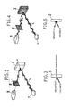
- FIG. 1 there is illustrated a detecting method according to the present invention.
- a large number of objects for the detection are transported on a belt conveyor or a vibrating feeder 3 to a drop chute 4.
- Such objects for the detection are transparent bodies such as, for example, pieces 1 of glass in which stones, pottery pieces and so forth may be mixed as opaque foreign articles 2, and here, the detecting method of the present invention is applied to detect such opaque foreign particles 2 from among glass pieces 1.
- the objects for the detecting are let to drop in a separated condition in several rows by a plurality of separating fins 5 of the drop chute 4.
- a laser beam emitted from a laser light source 6 is reflected by a polygon scanner 7 which is constantly rotating at a fixed speed in a predetermined direction so as to make for a scanning operation a linearly polarized laser beam L.
- the period of such scanning operation is determined such that a same object for the detection can be scanned two or more times while it drops. Accordingly, the object for the detection will be scanned not at the same location thereof by two or three times but at two or more different locations thereof.
- Reflected light from an object for the detection is introduced into a CCD (charge-coupled-device) camera 9 by way of a polarizing filter 8 and is detected as an electric signal by the CCD camera 9.
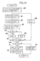
- a scanning light detecting sensor 10 step 51
- a detection signal of the scanning light detecting sensor 10 is divided into a pulse signal by a divider 11 and then fed back to the CCD camera 9 in order to control a scanning speed and period of the CCD camera 9 (step 52), for example, by way of a suitable control circuit (not shown).
- an analog signal of the CCD camera 9 is taken in (step 52) by the control circuit, and the start and the end of the data of the analog signal are detected as a preprocessing step (step 54) also by the control circuit. Then, the analog signal is binary digitized (step 55) by a binary digitizer (not shown), and the binary data obtained is checked by a determination circuit (not shown) to determine whether the object for the detection is either a glass piece 1 or an opaque foreign article 2 as hereinafter described (step 56).
- an air blow removing device 12 is controlled by a controlling circuit (not shown) therefore in response to a removing signal from the determination circuit so that the opaque foreign article 2 may be separated from glass pieces 1 by an air blow produced by the air blow removing device 12 while it is dropping (step 57).
- a linearly polarized laser beam L is irradiated upon glass pieces 1 and opaque foreign articles 2 which are dropping, and reflected light from them is detected by the CCD camera 9 by way of the polarizing filter 8.
- the linearly polarized laser beam L is irradiated upon a glass piece 1, most of it passes through the glass piece 1 while only a small fraction of it is reflected by the glass piece 1 as shonw in FIGS. 2 and 3.
- the reflecting face of the glass piece 1 is flat and accordingly reflects light regular strictly strictlyly, the light after it is reflected by the reflecting face of the glass piece 1 remains as linearly polarized light, and consequently, the reflected light will be cut by the polarizing filter 8 and will not be introduced into the CCD camera 9.
- the reflecting face of the glass piece 1 is uneven or has some scratches or the like thereon, or in case light is reflected from the opposite ends of the glass piece 1, the reflected light will be circularly polarized light, and only one component of the reflected light will pass through the polarizing filter 8 but is very small in amount.
- the output of the CCD camera 9 which may be an output of a CCD line sensor presents a great difference depending upon whether the object for the detection is a glass piece 1 or an opaque foreign article 2.
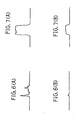
- FIGS. 6(A) and 6(B) show output waveforms when the CCD line sensor measures reflected light from a glass piece 1.
- FIG. 6(A) shows such output waveform when the polarizing filter 8 is not used
- FIG. 6(B) shows such output waveform when the polarizing filter 8 is used.
- FIGS. 7(A) and 7(B) show similar output waveforms when the CCD line sensor measures reflected light from an opaque foreign substance 2 without and with the polarizing filter 8 interposed in the passage of the reflected light, respectively.
- the polarizing filter 8 when the CCD camera 9 receives reflected light from a glass piece 1, it produces an output of a sawtooth waveform which exhibits large and irregular variations and is high in level, but when the CCD camera 9 receives reflected light from an opaque foreign article 2, it produces an output having a waveform resembling a rectangular waveform which exhibits small variations and is high in level and besides continuous in time, and although the two outputs are different in waveform, they do not have a great difference in level nor in duration.
- an output of the CCD camera 9 when it receives reflected light from a glass piece 1 makes a single sharp and short pulse which is low in level, but when the CCD camera 9 receives reflected light from an opaque foreign article 2, it produces an output in the form of a regular rectangular wave which is much higher in level than that of the former case and is sufficiently long in duration.
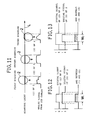
- a glass piece 1 is scanned three times by a linearly polarized laser beam L while it is dropping as shown in FIG. 8 (a scanned location of the glass piece 1 is displaced as the glass piece 1 drops), and analog signals from the CCD camera 9 upon first, second and third scanning operations which are taken in at step 53 of FIG. 1 are such as shown at (1) of 1, (2) of 1 and (3) of 1 of FIG. 8, respectively.
- an opaque foreign substance 2 is scanned by three times similarly by a linearly polarized laser beam L while it is dropping as shown in FIG. 11, and analog signals from the CCD camera 9 upon first, second and third scanning operations are such as shown at (1) of 2, (2) of 2 and (3) of 2 of FIG. 11, respectively.
- a width reference value W is set to a predetermined initial value and a transparent/opaque determination boundary value T is set first at step 60.
- a width and a position of a signal along a scanning line A are detected, and then at step 62, a width and a position of another signal along a next scanning line B (initially in the second scanning operation) are detected similarly, whereafter the signals from the lines A and B are ANDed (ANDed) at step 63.
- FIG. 9 is a time chart illustrating operations at steps 61 to 63 when a glass piece 1 is scanned as illustrated in FIG. 8, and FIG. 12 is a time chart illustrating similar operations when an opaque foreign substance 2 is scanned as illustrated in FIG. 11.
- step 64 it is judged whether or not the detected width W n is greater than the width reference value W (W n >W), and in case the former is greater than the latter, W n is stored as the width reference value W, that is, the detected width Wn is set as a new width reference value W, at step 65. On the contrary when W n is not greater than W, the detected width W n is not adopted, but W is maintained or stored as it is at step 66.
- step 65 or 66 advances from step 65 or 66 to step 67 at which it is judged whether or not there is a digital signal from a next scanning line, and in case there is a digital signal, the scanning lines A and B are advanced, at step 68, by one line to A+1 and B+1, respectively, and a width W n of an overlapping portion is detected similarly as described above (refer to FIGS. 10 and 13). Then, the processing from step 61 to step 65 or 66 is repeated until it is judged at step 67 that there is no digital signal any more.
- step 61 to step 65 or 66 Since the value of W n is updated as new W only at step 65 when W n is greater than W at step 64, the processing from step 61 to step 65 or 66 is after all processing to extract a maximum detected value W n among detected values from the first to last lines, and when it is judged at step 67 that there is no digital signal input any more, W exhibits such maximum detected value.
- the width of a digital signal originating from a glass piece 1 is small originally, and besides where the object for the detection is a glass piece 1, even if regularly reflected light is detected which exhibits an uneven waveform due to such local reflection as described above, since a location scanned by a laser beam is displaced for each scanning operation, the possibility that a similar regularly reflected condition may take place twice successively is very low and digital signals obtained by twice scanning operations are displaced in position in the scanning direction. Consequently, a detected width W n obtained by ANDing the thus displaced two digital signals is smaller than the width of any one of the digital signals.
- the width of a digital signal originating from an opaque foreign article 2 is small originally as shown in FIGS. 12 and 13, and besides where the object for the detection is an opaque foreign substance 2, reflected light of a high level is detected successively, and consequently, positions of digital signals obtained by twice scanning operations will be overlapped with each other. Consequently, a detected width W n obtained by ANDing the two digital signals is very great comparing with that obtained from signals originating from a glass piece 1. Besides, since only a maximum width value among them is adopted, the difference is increased further.
- step 69 it is judged whether or not the maximum detected value W is higher than the transparent/opaque determination boundary value T (W>T), and in case the former is not higher than the latter, it is determined at step 70 that the object for the detection is a glass piece 1. In this case, the air blow removing device 12 is not rendered operative.
- the air blow removing device 12 produces, by control at step 57 of FIG. 1, an air blow only at a position corresponding to the dropping opaque foreign article 2 to blow off and remove the opaque foreign article 2.
- such removal and scanning by a laser beam may otherwise be performed at any location other than the dropping location or may be performed by any other means than by an air blow. Further, it may be applicable to scan with a beam of light other than a laser beam, to AND digital signals obtained by three or more scanning operations or to detect reflected light by means of an optical sensor other than a CCD line sensor.
Landscapes
- General Health & Medical Sciences (AREA)
- Physics & Mathematics (AREA)
- Life Sciences & Earth Sciences (AREA)
- Chemical & Material Sciences (AREA)
- Analytical Chemistry (AREA)
- Biochemistry (AREA)
- Health & Medical Sciences (AREA)
- General Physics & Mathematics (AREA)
- Engineering & Computer Science (AREA)
- Pathology (AREA)
- Immunology (AREA)
- Multimedia (AREA)
- Investigating Materials By The Use Of Optical Means Adapted For Particular Applications (AREA)
- Sorting Of Articles (AREA)
Applications Claiming Priority (2)
| Application Number | Priority Date | Filing Date | Title |
|---|---|---|---|
| JP210573/89 | 1989-08-17 | ||
| JP1210573A JPH0781955B2 (ja) | 1989-08-17 | 1989-08-17 | 透明体中の不透明異物除去方法 |
Publications (3)
| Publication Number | Publication Date |
|---|---|
| EP0413522A2 true EP0413522A2 (de) | 1991-02-20 |
| EP0413522A3 EP0413522A3 (en) | 1992-08-12 |
| EP0413522B1 EP0413522B1 (de) | 1996-04-17 |
Family
ID=16591555
Family Applications (1)
| Application Number | Title | Priority Date | Filing Date |
|---|---|---|---|
| EP90308799A Expired - Lifetime EP0413522B1 (de) | 1989-08-17 | 1990-08-09 | Erfassung von undurchsichtigen Fremdartikeln unter durchsichtigen Körpern |
Country Status (5)
| Country | Link |
|---|---|
| US (1) | US5101101A (de) |
| EP (1) | EP0413522B1 (de) |
| JP (1) | JPH0781955B2 (de) |
| AU (1) | AU638268B2 (de) |
| DE (1) | DE69026554T2 (de) |
Cited By (6)
| Publication number | Priority date | Publication date | Assignee | Title |
|---|---|---|---|---|
| WO1993010913A1 (en) * | 1991-11-26 | 1993-06-10 | Alpine Technology, Inc. | Glass cullet separator and method of using same |
| EP0550944A1 (de) * | 1992-01-10 | 1993-07-14 | Toyo Glass Company Limited | Vorrichtung zum Sortieren von undurchsichtigen Fremdartikeln zwischen durchsichtigen Körpern |
| EP0737112A1 (de) * | 1993-12-30 | 1996-10-16 | Huron Valley Steel Corporation | System zur metallschrottsortierung |
| EP2039438A1 (de) * | 2007-09-21 | 2009-03-25 | Sanmak Industria de Maquinas S.A. | Zufuhrtransportbanddosierer mit einstellbarem Produktionsfluss |
| WO2012074552A2 (en) | 2010-12-01 | 2012-06-07 | Key Technology, Inc. | Sorting appartus |
| WO2013087649A1 (en) * | 2011-12-12 | 2013-06-20 | Visys Nv | A system and a method for individually inspecting objects in a stream of products and a sorting apparatus comprising such system |
Families Citing this family (19)
| Publication number | Priority date | Publication date | Assignee | Title |
|---|---|---|---|---|
| USRE36537E (en) * | 1990-10-29 | 2000-02-01 | National Recovery Technologies, Inc. | Method and apparatus for sorting materials using electromagnetic sensing |
| US5260576A (en) * | 1990-10-29 | 1993-11-09 | National Recovery Technologies, Inc. | Method and apparatus for the separation of materials using penetrating electromagnetic radiation |
| JPH05169037A (ja) * | 1991-12-17 | 1993-07-09 | Toyo Glass Co Ltd | 透明体中の不透明異物分別装置 |
| AU654317B2 (en) * | 1992-01-14 | 1994-11-03 | Toyo Glass Company Limited | Apparatus for sorting opaque foreign article from among transparent bodies |
| JPH06331556A (ja) * | 1993-05-21 | 1994-12-02 | Toyo Glass Co Ltd | 透明体中の不透明異物分別装置 |
| US5555984A (en) * | 1993-07-23 | 1996-09-17 | National Recovery Technologies, Inc. | Automated glass and plastic refuse sorter |
| DE4343058A1 (de) * | 1993-12-19 | 1995-06-22 | Robert Prof Dr Ing Massen | Multisensorielle Kamera für die Qualitätssicherung |
| JP2722376B2 (ja) * | 1994-10-04 | 1998-03-04 | 東洋ガラス株式会社 | 透明体中の異物除去装置 |
| KR100291478B1 (ko) * | 1998-09-08 | 2001-06-01 | 윤종용 | 셀룰러시스템에서유휴상태핸드오프방법및시스템 |
| US7024037B2 (en) * | 2002-03-22 | 2006-04-04 | Unilever Home & Personal Care Usa, A Division Of Conopco, Inc. | Cross-polarized imaging method for measuring skin ashing |
| US7009703B2 (en) * | 2003-03-27 | 2006-03-07 | J.M.Canty Inc. | Granular product inspection device |
| US20080302633A1 (en) * | 2007-06-05 | 2008-12-11 | Snow Gerald F | Apparatus and method for coating and inspecting objects |
| JP2010112943A (ja) * | 2008-10-08 | 2010-05-20 | Miyazaki Tlo:Kk | 異物混入判別装置および異物混入判別方法 |
| CN102205321A (zh) * | 2011-01-21 | 2011-10-05 | 安徽捷迅光电技术有限公司 | 多光源色选机 |
| CN102205322A (zh) * | 2011-01-21 | 2011-10-05 | 安徽捷迅光电技术有限公司 | 一种激光色选机 |
| ES2876328T3 (es) * | 2015-07-06 | 2021-11-12 | Tomra Sorting Gmbh | Dispositivo de boquilla y sistema para clasificar objetos |
| US9999906B2 (en) | 2016-06-29 | 2018-06-19 | John Bean Technologies Corporation | Sorter |
| US9785851B1 (en) | 2016-06-30 | 2017-10-10 | Huron Valley Steel Corporation | Scrap sorting system |
| CN109365321A (zh) * | 2018-11-20 | 2019-02-22 | 厦门理工学院 | 一种医用刺穿器检测机器 |
Citations (6)
| Publication number | Priority date | Publication date | Assignee | Title |
|---|---|---|---|---|
| GB784934A (en) * | 1953-02-23 | 1957-10-23 | Coal Industry Patents Ltd | Improvements in or relating to methods of and apparatus for sorting or distinguishing articles or materials |
| US3097744A (en) * | 1961-02-27 | 1963-07-16 | K & H Equipment Ltd | Quantitative photometric materials sorter |
| US3197647A (en) * | 1961-04-20 | 1965-07-27 | Gunsons Sortex Ltd | Photosensitive apparatus for sorting translucent objects |
| WO1988000501A1 (fr) * | 1985-01-16 | 1988-01-28 | Bsn | Dispositif de tri optique du groisil, c'est-a-dire d'une masse d'elements de verrre de recuperation ayant subi un broyage et comportant des elements infusibles ou refractaires, et installation comprenant de tels dispositifs |
| US4730932A (en) * | 1986-01-31 | 1988-03-15 | Kabushiki Kaisha Toshiba | Transmissivity inspection apparatus |
| EP0261840A2 (de) * | 1986-09-26 | 1988-03-30 | Pilkington Plc | Nachweis von ungewünschtem Material im Glassbruch |
Family Cites Families (3)
| Publication number | Priority date | Publication date | Assignee | Title |
|---|---|---|---|---|
| US4459023A (en) * | 1981-06-30 | 1984-07-10 | Kirin Beer Kabushiki Kaisha | Electro-optic inspection system for transparent or semitransparent containers |
| JPS59211812A (ja) * | 1983-05-17 | 1984-11-30 | Mitsubishi Electric Corp | 表面検査装置 |
| AU624432B2 (en) * | 1988-10-19 | 1992-06-11 | De Beers Industrial Diamond Division (Proprietary) Limited | Sorting method and apparatus |
-
1989
- 1989-08-17 JP JP1210573A patent/JPH0781955B2/ja not_active Expired - Lifetime
-
1990
- 1990-08-09 DE DE69026554T patent/DE69026554T2/de not_active Expired - Fee Related
- 1990-08-09 EP EP90308799A patent/EP0413522B1/de not_active Expired - Lifetime
- 1990-08-10 US US07/565,530 patent/US5101101A/en not_active Expired - Fee Related
- 1990-08-13 AU AU60949/90A patent/AU638268B2/en not_active Ceased
Patent Citations (6)
| Publication number | Priority date | Publication date | Assignee | Title |
|---|---|---|---|---|
| GB784934A (en) * | 1953-02-23 | 1957-10-23 | Coal Industry Patents Ltd | Improvements in or relating to methods of and apparatus for sorting or distinguishing articles or materials |
| US3097744A (en) * | 1961-02-27 | 1963-07-16 | K & H Equipment Ltd | Quantitative photometric materials sorter |
| US3197647A (en) * | 1961-04-20 | 1965-07-27 | Gunsons Sortex Ltd | Photosensitive apparatus for sorting translucent objects |
| WO1988000501A1 (fr) * | 1985-01-16 | 1988-01-28 | Bsn | Dispositif de tri optique du groisil, c'est-a-dire d'une masse d'elements de verrre de recuperation ayant subi un broyage et comportant des elements infusibles ou refractaires, et installation comprenant de tels dispositifs |
| US4730932A (en) * | 1986-01-31 | 1988-03-15 | Kabushiki Kaisha Toshiba | Transmissivity inspection apparatus |
| EP0261840A2 (de) * | 1986-09-26 | 1988-03-30 | Pilkington Plc | Nachweis von ungewünschtem Material im Glassbruch |
Cited By (12)
| Publication number | Priority date | Publication date | Assignee | Title |
|---|---|---|---|---|
| WO1993010913A1 (en) * | 1991-11-26 | 1993-06-10 | Alpine Technology, Inc. | Glass cullet separator and method of using same |
| US5350118A (en) * | 1991-11-26 | 1994-09-27 | Alpine Technology, Inc. | Glass cullet separator and method of using same |
| EP0550944A1 (de) * | 1992-01-10 | 1993-07-14 | Toyo Glass Company Limited | Vorrichtung zum Sortieren von undurchsichtigen Fremdartikeln zwischen durchsichtigen Körpern |
| US5273166A (en) * | 1992-01-10 | 1993-12-28 | Toyo Glass Company Limited | Apparatus for sorting opaque foreign article from among transparent bodies |
| EP0737112A1 (de) * | 1993-12-30 | 1996-10-16 | Huron Valley Steel Corporation | System zur metallschrottsortierung |
| EP0737112A4 (de) * | 1993-12-30 | 1998-12-02 | Huron Valley Steel Corp | System zur metallschrottsortierung |
| EP2039438A1 (de) * | 2007-09-21 | 2009-03-25 | Sanmak Industria de Maquinas S.A. | Zufuhrtransportbanddosierer mit einstellbarem Produktionsfluss |
| WO2012074552A2 (en) | 2010-12-01 | 2012-06-07 | Key Technology, Inc. | Sorting appartus |
| EP2646174A2 (de) * | 2010-12-01 | 2013-10-09 | Key Technology, Inc. | Sortiervorrichtung |
| EP2646174A4 (de) * | 2010-12-01 | 2014-11-12 | Key Technology Inc | Sortiervorrichtung |
| WO2013087649A1 (en) * | 2011-12-12 | 2013-06-20 | Visys Nv | A system and a method for individually inspecting objects in a stream of products and a sorting apparatus comprising such system |
| US9924105B2 (en) | 2011-12-12 | 2018-03-20 | Visys Nv | System and method for individually inspecting objects in a stream of products and a sorting apparatus comprising such system |
Also Published As
| Publication number | Publication date |
|---|---|
| JPH0781955B2 (ja) | 1995-09-06 |
| EP0413522A3 (en) | 1992-08-12 |
| DE69026554T2 (de) | 1996-11-21 |
| AU6094990A (en) | 1991-02-21 |
| AU638268B2 (en) | 1993-06-24 |
| JPH0375545A (ja) | 1991-03-29 |
| US5101101A (en) | 1992-03-31 |
| EP0413522B1 (de) | 1996-04-17 |
| DE69026554D1 (de) | 1996-05-23 |
Similar Documents
| Publication | Publication Date | Title |
|---|---|---|
| EP0413522B1 (de) | Erfassung von undurchsichtigen Fremdartikeln unter durchsichtigen Körpern | |
| US4105925A (en) | Optical object locator | |
| EP0090304B1 (de) | Vorrichtung zur Untersuchung von im wesentlichen runden Ojekten | |
| US4079416A (en) | Electronic image analyzing method and apparatus | |
| US4319269A (en) | External appearance inspecting system | |
| EP0550944B1 (de) | Vorrichtung zum Sortieren von undurchsichtigen Fremdartikeln zwischen durchsichtigen Körpern | |
| US3988530A (en) | Automatic defect-detecting method and apparatus | |
| US4666045A (en) | Pit detecting | |
| US4678920A (en) | Machine vision method and apparatus | |
| EP0227404B1 (de) | Sortierung | |
| US4943734A (en) | Inspection apparatus and method for detecting flaws on a diffractive surface | |
| US5111411A (en) | Object sorting system | |
| CA2050711A1 (en) | High resolution camera sensor having a linear pixel array | |
| US4260062A (en) | Foreign object discriminator for sorting apparatus | |
| US4281765A (en) | Article-detect signal separating network | |
| US4122952A (en) | Photometric sorters | |
| EP0369793A2 (de) | Verfahren und Vorrichtung zur Verarbeitung des Signals eines Strichkodelesers | |
| JP3694590B2 (ja) | 農産物の画像読取装置及びこれを用いた選別装置 | |
| GB1571836A (en) | Electronic image analyzer method and apparatus | |
| US5377282A (en) | Optical inspection system utilizing dynamic analog-to-digital thresholding | |
| US5142591A (en) | High resolution camera with hardware data compaction | |
| SU1036383A1 (ru) | Способ фотометрической сепарации кусковых материалов | |
| JP2575944B2 (ja) | 光線式選別装置 | |
| EP0297627B1 (de) | Verfahren zum Identifizieren von Objekten | |
| JP2738859B2 (ja) | 端部検出装置 |
Legal Events
| Date | Code | Title | Description |
|---|---|---|---|
| PUAI | Public reference made under article 153(3) epc to a published international application that has entered the european phase |
Free format text: ORIGINAL CODE: 0009012 |
|
| AK | Designated contracting states |
Kind code of ref document: A2 Designated state(s): DE FR GB |
|
| PUAL | Search report despatched |
Free format text: ORIGINAL CODE: 0009013 |
|
| AK | Designated contracting states |
Kind code of ref document: A3 Designated state(s): DE FR GB |
|
| 17P | Request for examination filed |
Effective date: 19921102 |
|
| 17Q | First examination report despatched |
Effective date: 19940817 |
|
| GRAA | (expected) grant |
Free format text: ORIGINAL CODE: 0009210 |
|
| AK | Designated contracting states |
Kind code of ref document: B1 Designated state(s): DE FR GB |
|
| REF | Corresponds to: |
Ref document number: 69026554 Country of ref document: DE Date of ref document: 19960523 |
|
| GRAH | Despatch of communication of intention to grant a patent |
Free format text: ORIGINAL CODE: EPIDOS IGRA |
|
| ET | Fr: translation filed | ||
| PLBE | No opposition filed within time limit |
Free format text: ORIGINAL CODE: 0009261 |
|
| STAA | Information on the status of an ep patent application or granted ep patent |
Free format text: STATUS: NO OPPOSITION FILED WITHIN TIME LIMIT |
|
| 26N | No opposition filed | ||
| PGFP | Annual fee paid to national office [announced via postgrant information from national office to epo] |
Ref country code: GB Payment date: 20010725 Year of fee payment: 12 |
|
| PGFP | Annual fee paid to national office [announced via postgrant information from national office to epo] |
Ref country code: FR Payment date: 20010727 Year of fee payment: 12 |
|
| PGFP | Annual fee paid to national office [announced via postgrant information from national office to epo] |
Ref country code: DE Payment date: 20011030 Year of fee payment: 12 |
|
| REG | Reference to a national code |
Ref country code: GB Ref legal event code: IF02 |
|
| PG25 | Lapsed in a contracting state [announced via postgrant information from national office to epo] |
Ref country code: GB Free format text: LAPSE BECAUSE OF NON-PAYMENT OF DUE FEES Effective date: 20020809 |
|
| PG25 | Lapsed in a contracting state [announced via postgrant information from national office to epo] |
Ref country code: DE Free format text: LAPSE BECAUSE OF NON-PAYMENT OF DUE FEES Effective date: 20030301 |
|
| GBPC | Gb: european patent ceased through non-payment of renewal fee |
Effective date: 20020809 |
|
| PG25 | Lapsed in a contracting state [announced via postgrant information from national office to epo] |
Ref country code: FR Free format text: LAPSE BECAUSE OF NON-PAYMENT OF DUE FEES Effective date: 20030430 |
|
| REG | Reference to a national code |
Ref country code: FR Ref legal event code: ST |