EP0412875B1 - Temperaturmessvorrichtung für Induktionskochgerät und Gerät mit einer solchen Vorrichtung - Google Patents
Temperaturmessvorrichtung für Induktionskochgerät und Gerät mit einer solchen Vorrichtung Download PDFInfo
- Publication number
- EP0412875B1 EP0412875B1 EP90402191A EP90402191A EP0412875B1 EP 0412875 B1 EP0412875 B1 EP 0412875B1 EP 90402191 A EP90402191 A EP 90402191A EP 90402191 A EP90402191 A EP 90402191A EP 0412875 B1 EP0412875 B1 EP 0412875B1
- Authority
- EP
- European Patent Office
- Prior art keywords
- temperature
- measuring
- inductor
- temperature according
- tongues
- Prior art date
- Legal status (The legal status is an assumption and is not a legal conclusion. Google has not performed a legal analysis and makes no representation as to the accuracy of the status listed.)
- Expired - Lifetime
Links
Images


Classifications
-
- G—PHYSICS
- G01—MEASURING; TESTING
- G01K—MEASURING TEMPERATURE; MEASURING QUANTITY OF HEAT; THERMALLY-SENSITIVE ELEMENTS NOT OTHERWISE PROVIDED FOR
- G01K1/00—Details of thermometers not specially adapted for particular types of thermometer
-
- H—ELECTRICITY
- H05—ELECTRIC TECHNIQUES NOT OTHERWISE PROVIDED FOR
- H05B—ELECTRIC HEATING; ELECTRIC LIGHT SOURCES NOT OTHERWISE PROVIDED FOR; CIRCUIT ARRANGEMENTS FOR ELECTRIC LIGHT SOURCES, IN GENERAL
- H05B6/00—Heating by electric, magnetic or electromagnetic fields
- H05B6/02—Induction heating
- H05B6/06—Control, e.g. of temperature, of power
- H05B6/062—Control, e.g. of temperature, of power for cooking plates or the like
-
- H—ELECTRICITY
- H05—ELECTRIC TECHNIQUES NOT OTHERWISE PROVIDED FOR
- H05B—ELECTRIC HEATING; ELECTRIC LIGHT SOURCES NOT OTHERWISE PROVIDED FOR; CIRCUIT ARRANGEMENTS FOR ELECTRIC LIGHT SOURCES, IN GENERAL
- H05B2213/00—Aspects relating both to resistive heating and to induction heating, covered by H05B3/00 and H05B6/00
- H05B2213/07—Heating plates with temperature control means
Definitions
- the invention relates mainly to a temperature measuring device for an induction cooking appliance and an appliance comprising such a device.
- a hob has a flat plate, for example a ceramic hob on which a pan is likely to be placed. This involves measuring the temperature of the contents of the pan, for example with a view to slaving.
- the measuring device must take into account that the bottom of the pans is not necessarily perfectly flat and that pans of various diameters can be used. With a concave or convex pan bottom, the point sensors placed in the center may not be in contact with the pan and therefore deliver false measurements.
- document US-A 3,786. 220 describes a temperature measurement device for an induction cooking appliance comprising a support for the container and an inductor placed under this support, the device being of the type comprising a temperature sensor fixed to a silicone rubber diaphragm.
- the assembly constituted by the sensor and the diaphragm is placed in an opening made in the support under the container, and the diaphragm has the function of closing the opening and allowing the sensor to always be in contact with the bottom of the container, even if it is light or has deformations.
- the maximum heating is obtained at a diameter corresponding to half the inductor diameter.
- the temperature of the bottom of the pan is higher than the temperature of its contents, for example oil, which we want to be able to measure.
- the temperature is lower. It is close to that of the contents of the pan.
- the point sensors placed on the periphery may not be able to measure the temperature of small diameter pans.
- the low-power induction hobs have been fitted with aluminum plates placed in thermal contact with the temperature sensors.
- This aluminum plate which is a good thermal conductor allows the temperature to be averaged over a larger area.
- the present invention is based on the discovery that the temperature measurements with the device of known type comprising an aluminum plate were distorted by the heating of said aluminum plate by the current induced by the inductor. This is particularly serious in the case where the temperature measurement is used to control it. Indeed, the induction currents will heat the aluminum plate and distort the temperature measurement which in turn will regulate the power of the induction current. This results in completely erratic behavior.
- the use of aluminum plates is perfectly impossible in the case of induction hobs of normal power or high power.
- heating the aluminum plate risks damaging or destroying the temperature sensors and the inductor.
- the temperature measured is mainly a function of the currents induced in the aluminum plate and is only slightly influenced by the baking temperature.
- Document FR-A-2,260,249 teaches that, in order to reduce the currents induced in an electric film conductive used, in an induction heater, to reduce or prevent an electrostatic connection between the container and the inductor, it is necessary to give this film, a configuration such that it does not form a closed loop.
- the object of the present invention is to accurately measure the temperature of a container or its contents heated by an induction hob, regardless of the shape of this container.
- the device according to the present invention comprises a temperature detector thermally connected to a heat conductor comprising means making it possible to reduce the electromagnetic power absorbed by the heat conductor, by reducing the intensity of induced current. For this, the electrical circumferential resistance is increased while trying to disturb the radial thermal conduction as little as possible.
- the invention mainly relates to a measuring device as defined in claims 1 to 12.
- the invention also relates to a hob as defined in claims 13 and 14.
- FIGS. 1 to 11 the same references have been used to designate the same elements.
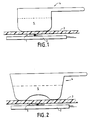
- FIG 1 we can see an induction hob of known type.
- the hob has an inductor 2, a temperature sensor 1, a pan support 3, for example a glass-ceramic plate.
- the inductor 2 traversed by a current is intended to generate in the pan 4 currents which by Joule effect will cause an increase in the temperature of the contents 5 of the pan 4.
- the temperature sensor 1 is intended to measure the temperature of the contents 5 of the pan 4, of the pan 4 or of the ceramic hob 3.
- the temperature sensor 1 makes it possible to control the temperature to a set value fixed by the control members or to a given heating sequence or to display a signal d alarm intended to avoid hand contact with a hot plate.
- the temperature control allows to obtain the desired cooking and prevent the deterioration of the pan.
- the sensor 1 placed in the center of the inductor 2 can deliver a signal characteristic of the temperature of the contents 5 of the pan 4.
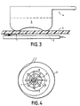
- the pans have a concave bottom.
- the temperature sensor 1 will be on a part of the ceramic hob 3 which is not in contact with the bottom of the pan 4.
- the signal delivered by the sensor 1 will not be more characteristic of the temperature of the content 5 of the pan 4.
- the temperature of the sensor 1 risks being significantly lower than the temperature of the content 5 of the pan 4.
- a temperature measuring device On the inductor 2 the temperature sensor 1 is placed.
- the temperature sensor 1 is advantageously a diode with negative temperature coefficient (NTC).
- NTC negative temperature coefficient
- thermocouples thermocouples
- thermoresistors does not depart from the scope of the present invention.
- a thermal conductor 6 is brought into thermal contact with the sensor 1. It is possible to provide electrical insulation of the thermal conductor with respect to the inductor 1 to guarantee the safety of users. This electrical insulation will be constituted for example by a thin dielectric film or a heat-conducting grease so as not to disturb the thermal conduction.
- the thermal conductor 6 It is important to minimize the heating of the thermal conductor 6 by electromagnetic radiation from the inductor 2. It is advantageous to use metal parts, for example plates of aluminum, brass, copper or copper alloy. A reduction in the heat induced in the inductor 2 is obtained by the choice of the material and especially of the geometry of the thermal conductor 6.
- the inductor 2 induces circumferential currents.
- the circumferential electrical resistance of the conductor 6 is increased so as to decrease the intensity of the induced currents.
- the increase in resistance is caused by radial cut-outs 8.
- the thermal conductor 6 has the shape of stars comprising radial tongues 7 ensuring thermal conduction.
- FIG. 4 the thermal conductor 6 has the shape of stars comprising radial tongues 7 ensuring thermal conduction.
- the thermal conductor 6 has a thickness of a few tenths of a millimeter.
- metal plates whose total thickness is greater ensuring better conduction while avoiding current induction in the thickness of the thermal conductor 6.
- conductive braids to achieve the heat conductor.
- the thermal conductor is covered by the container whose temperature is to be measured.
- the diameter of the thermal conductor is of the same order as that of the pan of the smallest diameter that one wants to be able to use.
- part of the thermal conductor 6 is not covered by the pan, since it is the hottest part which will determine the temperature at which the sensor 1 is worn, the measurement is only weakly disturbed.
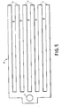
- the temperature sensor 1 is placed on an enlargement of the base of the thermal conductor 6. On this base leave six parallel tongues 7 separated by five cutouts 8.
- the base has a thickness of 4 mm, its widening has a thickness of 3.5 mm and each tab 7 and cutout 8 has a width of 2 mm.
- the temperature sensor 1 is placed for example near the edge of the inductor 2. For embodiments in which it is desired to place the sensor 1 in the center of the inductor 2 (not shown in FIG. 5) it may prove advantageous to use a thermal conductor 6 additionally comprising six other tabs 7 placed symmetrically with respect to the temperature sensor 1.
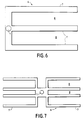
- FIG. 7 an exemplary embodiment of the device according to the present invention can be seen comprising two sets of four tabs 7 placed symmetrically with respect to the temperature sensor 1. This set is intended to be placed in the center of the inductor 2 (not shown in Figure 7).
- FIG 8 one can see an embodiment of the device according to the present invention comprising four tongues 7 starting from a circular base.
- the temperature sensor 1 is placed on the circular base.
- the circular base is placed either on the edge of the inductor 2 (not shown in the figure) or concentrically with this edge.
- FIG. 9 an exemplary embodiment of the device according to the present invention can be seen in which the cutouts 8 have the form of grooves of small thickness.
- the thermal conductor 6 is a simple plate in which radial grooves have been made. At the center of the plate is placed the temperature sensor 1. It is of course possible to use circular plates without departing from the scope of the present invention.
- FIG. 10 one can see an embodiment of the plates having grooves 8 forming tongues 7 of typically constant width 2 mm.
- the temperature sensor 1 is placed in the center of the thermal conductor 6.
- the resistivity of the heat conductor 6 can be varied locally or globally.
- heat conductors of very low resistance are used, for example copper or silver, so as to reduce losses by the Joule effect.
- the resistivity of the heat conductor 6 is locally increased so as to decrease the intensity of induced current.
- the induction hob comprises four inductors 2. It is understood that the hobs comprising a different number of inductors 2 do not depart from the scope of the present invention.
- the inductors 2 are equipped with temperature measuring devices according to the present invention comprising heat conductors 6.
- the induction table according to the present invention comprises a control device 10.
- the control device 10 is connected to the power sector. supply 11, to control devices 9, to temperature measurement devices, to inductors 2 and, advantageously to a device 12 for displaying the presence of residual temperature of the glass-ceramic plate 3.
- the control device 10 comprises a regulation microprocessor associated with a memory containing the various operating programs.
- a keyboard 15 makes it possible to give instructions for the desired cooking.
- a display 16 connected to the control device 10 makes it possible to display the choice that is being made, to facilitate ordering and / or display information relating to cooking (time remaining, temperature, type of program chosen, instantaneous power, energy consumed).
- the control device 10 is connected to a power generator 17 by a line 20 transmitting the power setpoints.
- the power generator 17 is connected by a line 21 to the control device 10 by which it communicates the current and voltage measurements to it at the level of the inductors 2.
- the power generator 17 is connected to the inductor 2 by a relay 18 controlled by a line 19 coming from the control device 10.
- the temperature measurement device indicates to the control device 10 the temperature of the content of a container placed on the inductor 2.
- the temperature measurement device is connected to the input of an amplifier 13
- the output of the amplifier 13 is connected to the input of an analog-digital converter 14.
- the output of the analog-digital converter 14 is connected to the control device 10.
- a single inductor 2 has been shown. It is understood that one can use any number of inductors 2, for example 1,2,3,4,5 or 6 without departing from the scope of the present invention.
- the control device 10 supplies the inductors 2, as a function of the set values selected on the control devices 9 and the temperature measurements provided by the measurement device, of the electric currents of voltage, current and frequency necessary for the rise or maintain the desired temperature of a pan or its contents (not shown in Figure 11).
- the control devices 9 are for example rotary knobs or push buttons to select the cooking speed, power or temperature desired. They can advantageously be associated with a digital or alpha-digital display of the selected choice.
- the residual heat display device 12 includes, for example, light-emitting diodes (LED in English terminology) which are lit as long as the temperature of the glass-ceramic plate 3 is greater than 60 ° C.
- the device 12 comprises either a single diode or a light-emitting diode by inductor 2.
- the device according to the present invention applies to the measurement of temperature during induction heating.
- the present invention applies mainly to temperature measurements of containers or their contents during cooking using induction hobs.
Landscapes
- Physics & Mathematics (AREA)
- Electromagnetism (AREA)
- General Physics & Mathematics (AREA)
- Cookers (AREA)
- Induction Heating Cooking Devices (AREA)
- Measuring Temperature Or Quantity Of Heat (AREA)
- General Induction Heating (AREA)
Claims (14)
- Vorrichtung zur Messung der Temperatur eines von einem Induktions-Kochgerät erwärmten Behälters (4) oder Produkts (5), wobei das Kochgerät einen Träger (3) für den Behälter und einen unter dem Träger (3) angeordneten Induktor (2) aufweist und wobei die Vorrichtung eine Temperaturmeßsonde (1), die einen Meßwert der Temperatur liefert, und einen Wärmeleiter (6) aufweist, der unter dem Träger angeordnet ist und mit der Temperaturmeßsonde (1) in Wärmekontakt steht, so daß er mindestens teilweise vom Behälter (4) bedeckt wird, dadurch gekennzeichnet, daß der Wärmeleiter (6) mit dem Träger (3) in Wärmekontakt steht, aus einem metallischen Material besteht und eine optimierte geometrische Form besitzt, um die Temperatur auf einen Mittelwert zu bringen und um den elektrischen Widerstand am Umfang des Wärmeleiters zu erhöhen und gleichzeitig die Verringerung der radialen Wärmeleitung zu minimieren, wobei die geometrische Form des Wärmeleiters (6) eine Vielzahl von Zungen (7) aufweist, die von einer gemeinsamen Basis ausgehen, auf der die Temperaturmeßsonde (1) angeordnet ist.
- Temperatur-Meßvorrichtung nach Anspruch 1, dadurch gekennzeichnet, daß die gemeinsame Basis und die Temperaturmeßsonde sich im Zentrum des Induktors (2) befinden.
- Temperatur-Meßvorrichtung nach Anspruch 1, dadurch gekennzeichnet, daß die gemeinsame Basis und die Temperaturmeßsonde sich in der Nähe des Rands des Induktors befinden.
- Temperatur-Meßvorrichtung nach einem beliebigen der Ansprüche 1 oder 2, dadurch gekennzeichnet, daß die Zungen (7) sich radial um die gemeinsame Basis herum erstrecken.
- Temperatur-Meßvorrichtung nach einem beliebigen der Ansprüche 1 bis 3, dadurch gekennzeichnet, daß die Zungen (7) parallel verlaufen.
- Temperatur-Meßvorrichtung nach einem beliebigen der Ansprüche 1 bis 3, dadurch gekennzeichnet, daß die Zungen (7) konvergierend verlaufen.
- Temperatur-Meßvorrichtung nach einem beliebigen der Ansprüche 1 oder 2, dadurch gekennzeichnet, daß die Zungen (7) in zwei Einheiten von parallelen Zungen gruppiert sind, die sich zu beiden Seiten der gemeinsamen Basis erstrecken.
- Temperatur-Meßvorrichtung nach einem beliebigen der Ansprüche 1 bis 7, dadurch gekennzeichnet, daß die Breite der Zungen im wesentlichen 2 mm beträgt.
- Temperatur-Meßvorrichtung nach einem beliebigen der vorhergehenden Ansprüche, dadurch gekennzeichnet, daß der Wärmeleiter (5) aus Aluminium ist.
- Temperatur-Meßvorrichtung nach einem beliebigen der Ansprüche 1 bis 8, dadurch gekennzeichnet, daß der Wärmeleiter (6) aus Kupfer ist.
- Temperatur-Meßvorrichtung nach einem beliebigen der vorhergehenden Ansprüche, dadurch gekennzeichnet, daß die Temperaturmeßsonde (1) eine Sonde mit einem negativem Temperaturkoeffizienten (CNT) ist.
- Temperatur-Meßvorrichtung nach Anspruch 11, dadurch gekennzeichnet, daß die Temperaturmeßsonde eine Diode ist.
- Kochfeld mit einem Induktor (2) und einer Kontrollvorrichtung (10), die die Stromstärke, die Spannung und/oder die Frequenz des dem Induktor (2) gelieferten Stroms kontrolliert, dadurch gekennzeichnet, daß der Induktor mit einer Temperatur-Meßvorrichtung gemäß einem beliebigen der vorhergehenden Ansprüche ausgestattet ist.
- Kochfeld nach Anspruch 13, dadurch gekennzeichnet, daß die Kontrollvorrichtung (10) mit der Meßvorrichtung und einer Steuervorrichtung (9) zur Auswahl eines Sollwerts verbunden ist, und daß die Kontrollvorrichtung die Temperatur des Behälters oder seines Inhalts auf den Sollwert gemäß den von der Meßvorrichtung gelieferten Temperaturmeßwerten nachregelt.
Applications Claiming Priority (2)
| Application Number | Priority Date | Filing Date | Title |
|---|---|---|---|
| FR8910527A FR2650669B1 (fr) | 1989-08-04 | 1989-08-04 | Dispositif de mesure de temperature pour appareil de cuisson a induction et appareil comportant un tel dispositif |
| FR8910527 | 1989-08-04 |
Publications (2)
| Publication Number | Publication Date |
|---|---|
| EP0412875A1 EP0412875A1 (de) | 1991-02-13 |
| EP0412875B1 true EP0412875B1 (de) | 1996-04-17 |
Family
ID=9384479
Family Applications (1)
| Application Number | Title | Priority Date | Filing Date |
|---|---|---|---|
| EP90402191A Expired - Lifetime EP0412875B1 (de) | 1989-08-04 | 1990-07-31 | Temperaturmessvorrichtung für Induktionskochgerät und Gerät mit einer solchen Vorrichtung |
Country Status (7)
| Country | Link |
|---|---|
| US (1) | US5283412A (de) |
| EP (1) | EP0412875B1 (de) |
| JP (1) | JPH03141579A (de) |
| KR (1) | KR910005043A (de) |
| CA (1) | CA2021003A1 (de) |
| DE (1) | DE69026553T2 (de) |
| FR (1) | FR2650669B1 (de) |
Cited By (1)
| Publication number | Priority date | Publication date | Assignee | Title |
|---|---|---|---|---|
| USRE42513E1 (en) | 2003-01-30 | 2011-07-05 | Hr Technology, Inc. | RFID—controlled smart range and method of cooking and heating |
Families Citing this family (19)
| Publication number | Priority date | Publication date | Assignee | Title |
|---|---|---|---|---|
| FR2783370B1 (fr) * | 1998-09-11 | 2000-12-08 | Cepem | Dispositif d'alimentation a onduleur dont la puissance delivree est controlee |
| US6127659A (en) * | 1999-04-26 | 2000-10-03 | Hardt Equipment Manufacturing Inc. | Food warmer |
| DE10121534A1 (de) * | 2001-05-03 | 2002-11-07 | Bsh Bosch Siemens Hausgeraete | Anzeigevorrichtung |
| DE10240372B4 (de) * | 2002-09-02 | 2004-09-02 | Paschal-Werk G. Maier Gmbh | Rundschalung |
| US7118273B1 (en) | 2003-04-10 | 2006-10-10 | Transmeta Corporation | System for on-chip temperature measurement in integrated circuits |
| DE102007006280A1 (de) * | 2007-01-31 | 2008-08-07 | E.G.O. Elektro-Gerätebau GmbH | Verfahren zum Aufbau eines Induktionskochfeldes und Induktionskochfeld |
| JP4642129B2 (ja) | 2008-11-06 | 2011-03-02 | ローム株式会社 | Ledランプ |
| ES2352772B1 (es) * | 2008-12-19 | 2012-01-26 | Bsh Electrodomésticos España, S.A. | Campo de cocción con varios elementos de calentamiento y al menos un grupo constructivo de la electrónica de potencia. |
| CN201368498Y (zh) * | 2009-03-06 | 2009-12-23 | 东莞市前锋电子有限公司 | 电磁加热式器具的温度控制装置 |
| EP2337426B1 (de) * | 2009-12-19 | 2014-08-20 | Electrolux Home Products Corporation N.V. | Induktionskochfeld mit Induktionsspulen und Vorrichtung zur Bestimmung der Induktionsspulentemperatur |
| KR101513698B1 (ko) * | 2010-07-28 | 2015-04-20 | 삼성전자 주식회사 | 온도센서 및 이를 갖는 유도가열조리기 |
| FR2965330A1 (fr) * | 2010-09-23 | 2012-03-30 | Jaeger | Capteur pour inducteur ameliore |
| FR2966687B1 (fr) | 2010-10-21 | 2016-11-04 | Fagorbrandt Sas | Dispositif de mesure de temperature d'un groupe d'inducteurs d'une table de cuisson a induction et table de cuisson a induction associee. |
| ES2428243R1 (es) * | 2012-02-10 | 2013-12-10 | Bsh Electrodomesticos Espana | Aparato de cocción y procedimiento para la regulación de la temperatura en dicho aparato |
| EP3216315B1 (de) * | 2014-11-07 | 2019-07-17 | Breville PTY Limited | Kochfeld |
| FR3033404B1 (fr) | 2015-03-03 | 2020-10-02 | Groupe Brandt | Dispositif pour mesurer la temperature, notamment pour table de cuisson |
| KR102480703B1 (ko) * | 2016-01-29 | 2022-12-22 | 엘지전자 주식회사 | 유도가열 조리기기 |
| IT201900010230A1 (it) * | 2019-06-27 | 2020-12-27 | Latini Elio E C Sas | Dispositivo di protezione e sicurezza di un sistema di cottura e/o riscaldamento ad induzione |
| CN113543394A (zh) * | 2020-04-15 | 2021-10-22 | 麦启康 | 便携式主动控温装置 |
Family Cites Families (16)
| Publication number | Priority date | Publication date | Assignee | Title |
|---|---|---|---|---|
| US3191003A (en) * | 1961-12-21 | 1965-06-22 | Gen Electric | Surface heating unit |
| NL6403651A (de) * | 1963-06-01 | 1964-12-02 | ||
| US3530499A (en) * | 1969-09-29 | 1970-09-22 | Charles F Schroeder | Electrically heated appliance unit |
| US3624352A (en) * | 1970-09-22 | 1971-11-30 | Gen Motors Corp | Ceramic top range surface temperature cut-off thermostatic device |
| US3710062A (en) * | 1971-04-06 | 1973-01-09 | Environment One Corp | Metal base cookware induction heating apparatus having improved power supply and gating control circuit using infra-red temperature sensor and improved induction heating coil arrangement |
| US3786220A (en) * | 1971-12-29 | 1974-01-15 | Gen Electric | Induction cooking appliance including temperature sensing of inductively heated cooking vessel |
| US3843857A (en) * | 1972-05-26 | 1974-10-22 | R Cunningham | Induction heating system primarily intended for cooking use |
| US3796850A (en) * | 1973-05-31 | 1974-03-12 | Westinghouse Electric Corp | Pan detector for induction heating cooking unit |
| JPS5421982B2 (de) * | 1974-02-05 | 1979-08-03 | ||
| US4013859A (en) * | 1975-06-04 | 1977-03-22 | Environment/One Corporation | Induction cooking unit having cooking load sensing device and essentially zero stand-by power loss |
| US4194826A (en) * | 1978-09-05 | 1980-03-25 | Energy Conversion Devices, Inc. | System for developing heat responsive film |
| US4319109A (en) * | 1979-12-28 | 1982-03-09 | General Electric Company | Centered utensil sensor for induction surface units |
| DE8109131U1 (de) * | 1981-03-27 | 1981-08-20 | E.G.O. Elektro-Geräte Blanc u. Fischer, 7519 Oberderdingen | Temperaturfuehlanordnung fuer elektrische strahlheizkoerper |
| FR2518746A1 (fr) * | 1981-12-23 | 1983-06-24 | Europ Composants Electron | Capteur de temperature et dispositif l'incorporant |
| US4499368A (en) * | 1984-03-05 | 1985-02-12 | General Electric Company | Utensil removal detection system for cooking appliance |
| US4665292A (en) * | 1986-01-06 | 1987-05-12 | General Electric Company | Boil point prediction arrangement for cooking appliance |
-
1989
- 1989-08-04 FR FR8910527A patent/FR2650669B1/fr not_active Expired - Lifetime
-
1990
- 1990-07-12 CA CA002021003A patent/CA2021003A1/en not_active Abandoned
- 1990-07-13 US US07/552,097 patent/US5283412A/en not_active Expired - Lifetime
- 1990-07-31 DE DE69026553T patent/DE69026553T2/de not_active Expired - Lifetime
- 1990-07-31 EP EP90402191A patent/EP0412875B1/de not_active Expired - Lifetime
- 1990-08-02 KR KR1019900011861A patent/KR910005043A/ko not_active Application Discontinuation
- 1990-08-03 JP JP2206661A patent/JPH03141579A/ja active Pending
Cited By (1)
| Publication number | Priority date | Publication date | Assignee | Title |
|---|---|---|---|---|
| USRE42513E1 (en) | 2003-01-30 | 2011-07-05 | Hr Technology, Inc. | RFID—controlled smart range and method of cooking and heating |
Also Published As
| Publication number | Publication date |
|---|---|
| DE69026553T2 (de) | 1996-09-12 |
| JPH03141579A (ja) | 1991-06-17 |
| CA2021003A1 (en) | 1991-02-05 |
| EP0412875A1 (de) | 1991-02-13 |
| DE69026553D1 (de) | 1996-05-23 |
| FR2650669A1 (fr) | 1991-02-08 |
| KR910005043A (ko) | 1991-03-29 |
| US5283412A (en) | 1994-02-01 |
| FR2650669B1 (fr) | 1993-10-29 |
Similar Documents
| Publication | Publication Date | Title |
|---|---|---|
| EP0412875B1 (de) | Temperaturmessvorrichtung für Induktionskochgerät und Gerät mit einer solchen Vorrichtung | |
| EP0931496B1 (de) | Küchengerät mit einem Temperatursensor zum Messen seiner Temperatur | |
| FR2488680A1 (fr) | Cuisiniere electrique | |
| EP0394148A1 (de) | Abnehmbare elektrische Heizplatte | |
| EP2037783B1 (de) | Nahrungsmittel mit möglichkeit der erfassung seiner temperatur durch einen herd | |
| WO2015033060A1 (fr) | Calotte d'un recipient de cuisson comportant un support muni d'un dispositif electrique | |
| EP1137324A1 (de) | Induktive Heizvorrichtung für Kochbehälter | |
| FR2608882A1 (fr) | Agencement de protection thermique pour table de cuisson en verre a disque massif | |
| WO2011132614A1 (ja) | 誘導加熱調理器 | |
| EP2454919A1 (de) | Vorrichtung zum induktiven erwärmen | |
| FR2846509A1 (fr) | Element chauffant blinde a effet ctp | |
| EP3711455B1 (de) | Vorrichtung zur begrenzung oder regelung der temperatur bei einem kochutensil | |
| FR2640401A1 (fr) | Dispositif de commande electronique de l'alimentation d'une resistance chauffante | |
| EP2874524B1 (de) | Kulinarischer artikel, anordnung und system mit detektion von flüchtigen verbindungen und verfahren zur herstellung des kulinarischen artikels | |
| EP1051099B1 (de) | Thermostat mit thermistor und schaltrelais für heizwiderstände in einem haushaltsgerät | |
| EP0623303B1 (de) | Elektrisches Kochgerät | |
| FR2710512A1 (fr) | Ustensile de cuisine à sonde de température. | |
| EP2440007A2 (de) | Steuerverfahren bei Betrieb einer Reihe von Induktoren eines Induktionskochfeldes, und zugehöriges Induktionskochfeld | |
| JP2010252832A (ja) | 加熱調理器 | |
| EP3890432A1 (de) | Kochplatte, die ein verbessertes kochprogramm umfasst, kochsystem, kochverfahren und entsprechendes programm | |
| WO2020169111A1 (en) | Control system for cooking device | |
| FR2674318A3 (fr) | Appareil de cuisson portatif. | |
| EP0025756B1 (de) | Regelungsschaltung für die Temperatur eines Backofens, insbesondere zum häuslichen Gebrauch | |
| FR2810526A1 (fr) | Recipient chauffant pour appareil electromenager chauffe liquides | |
| FR3067239B1 (fr) | Dispositif de chauffage d'un recipient de cuisson |
Legal Events
| Date | Code | Title | Description |
|---|---|---|---|
| PUAI | Public reference made under article 153(3) epc to a published international application that has entered the european phase |
Free format text: ORIGINAL CODE: 0009012 |
|
| AK | Designated contracting states |
Kind code of ref document: A1 Designated state(s): BE DE ES FR GB IT LU NL SE |
|
| 17P | Request for examination filed |
Effective date: 19910322 |
|
| 17Q | First examination report despatched |
Effective date: 19931021 |
|
| GRAA | (expected) grant |
Free format text: ORIGINAL CODE: 0009210 |
|
| AK | Designated contracting states |
Kind code of ref document: B1 Designated state(s): BE DE ES FR GB IT LU NL SE |
|
| PG25 | Lapsed in a contracting state [announced via postgrant information from national office to epo] |
Ref country code: IT Free format text: LAPSE BECAUSE OF FAILURE TO SUBMIT A TRANSLATION OF THE DESCRIPTION OR TO PAY THE FEE WITHIN THE PRESCRIBED TIME-LIMIT;WARNING: LAPSES OF ITALIAN PATENTS WITH EFFECTIVE DATE BEFORE 2007 MAY HAVE OCCURRED AT ANY TIME BEFORE 2007. THE CORRECT EFFECTIVE DATE MAY BE DIFFERENT FROM THE ONE RECORDED. Effective date: 19960417 Ref country code: ES Free format text: THE PATENT HAS BEEN ANNULLED BY A DECISION OF A NATIONAL AUTHORITY Effective date: 19960417 Ref country code: GB Effective date: 19960417 |
|
| REF | Corresponds to: |
Ref document number: 69026553 Country of ref document: DE Date of ref document: 19960523 |
|
| PG25 | Lapsed in a contracting state [announced via postgrant information from national office to epo] |
Ref country code: SE Effective date: 19960717 |
|
| PG25 | Lapsed in a contracting state [announced via postgrant information from national office to epo] |
Ref country code: LU Free format text: LAPSE BECAUSE OF NON-PAYMENT OF DUE FEES Effective date: 19960731 |
|
| GRAH | Despatch of communication of intention to grant a patent |
Free format text: ORIGINAL CODE: EPIDOS IGRA |
|
| GBV | Gb: ep patent (uk) treated as always having been void in accordance with gb section 77(7)/1977 [no translation filed] |
Effective date: 19960417 |
|
| PLBE | No opposition filed within time limit |
Free format text: ORIGINAL CODE: 0009261 |
|
| STAA | Information on the status of an ep patent application or granted ep patent |
Free format text: STATUS: NO OPPOSITION FILED WITHIN TIME LIMIT |
|
| 26N | No opposition filed | ||
| REG | Reference to a national code |
Ref country code: FR Ref legal event code: CA Ref country code: FR Ref legal event code: CD Ref country code: FR Ref legal event code: TP |
|
| BECA | Be: change of holder's address |
Owner name: BRANDT INDUSTRIES7 RUE HENRI BECQUEREL, F-92500 RU Effective date: 20071219 |
|
| BECH | Be: change of holder |
Owner name: BRANDT INDUSTRIES7 RUE HENRI BECQUEREL, F-92500 RU Effective date: 20071219 |
|
| BECN | Be: change of holder's name |
Owner name: BRANDT INDUSTRIES Effective date: 20071219 |
|
| NLS | Nl: assignments of ep-patents |
Owner name: COMPAGNIE EUROPEENNE DE FABRICATION D'ENCEINTES MI Effective date: 20071018 Owner name: BRANDT INDUSTRIES Effective date: 20071018 |
|
| NLT1 | Nl: modifications of names registered in virtue of documents presented to the patent office pursuant to art. 16 a, paragraph 1 |
Owner name: BRANDT COOKING |
|
| PGFP | Annual fee paid to national office [announced via postgrant information from national office to epo] |
Ref country code: NL Payment date: 20080731 Year of fee payment: 19 |
|
| PGFP | Annual fee paid to national office [announced via postgrant information from national office to epo] |
Ref country code: BE Payment date: 20080901 Year of fee payment: 19 |
|
| PGFP | Annual fee paid to national office [announced via postgrant information from national office to epo] |
Ref country code: FR Payment date: 20090731 Year of fee payment: 20 |
|
| PGFP | Annual fee paid to national office [announced via postgrant information from national office to epo] |
Ref country code: DE Payment date: 20090812 Year of fee payment: 20 |
|
| BERE | Be: lapsed |
Owner name: BRANDT INDUSTRIES Effective date: 20090731 |
|
| NLV4 | Nl: lapsed or anulled due to non-payment of the annual fee |
Effective date: 20100201 |
|
| PG25 | Lapsed in a contracting state [announced via postgrant information from national office to epo] |
Ref country code: BE Free format text: LAPSE BECAUSE OF NON-PAYMENT OF DUE FEES Effective date: 20090731 |
|
| PG25 | Lapsed in a contracting state [announced via postgrant information from national office to epo] |
Ref country code: NL Free format text: LAPSE BECAUSE OF NON-PAYMENT OF DUE FEES Effective date: 20100201 |
|
| PG25 | Lapsed in a contracting state [announced via postgrant information from national office to epo] |
Ref country code: DE Free format text: LAPSE BECAUSE OF EXPIRATION OF PROTECTION Effective date: 20100731 |