EP0412643B1 - Durchflussregelungsanordnung für Tintenkartuschen - Google Patents
Durchflussregelungsanordnung für Tintenkartuschen Download PDFInfo
- Publication number
- EP0412643B1 EP0412643B1 EP90306809A EP90306809A EP0412643B1 EP 0412643 B1 EP0412643 B1 EP 0412643B1 EP 90306809 A EP90306809 A EP 90306809A EP 90306809 A EP90306809 A EP 90306809A EP 0412643 B1 EP0412643 B1 EP 0412643B1
- Authority
- EP
- European Patent Office
- Prior art keywords
- ink
- conduit
- reservoir
- control member
- cartridge
- Prior art date
- Legal status (The legal status is an assumption and is not a legal conclusion. Google has not performed a legal analysis and makes no representation as to the accuracy of the status listed.)
- Expired - Lifetime
Links
- 238000007639 printing Methods 0.000 claims description 13
- 238000004891 communication Methods 0.000 claims description 7
- 239000012530 fluid Substances 0.000 claims description 7
- 230000000903 blocking effect Effects 0.000 claims description 2
- 230000003247 decreasing effect Effects 0.000 claims description 2
- 239000004033 plastic Substances 0.000 claims description 2
- 238000000034 method Methods 0.000 description 4
- 238000013461 design Methods 0.000 description 3
- 239000000758 substrate Substances 0.000 description 3
- 230000009471 action Effects 0.000 description 2
- 230000007423 decrease Effects 0.000 description 2
- 238000012423 maintenance Methods 0.000 description 2
- 239000000463 material Substances 0.000 description 2
- 239000004743 Polypropylene Substances 0.000 description 1
- 229910000831 Steel Inorganic materials 0.000 description 1
- 239000006096 absorbing agent Substances 0.000 description 1
- 238000010521 absorption reaction Methods 0.000 description 1
- 230000004913 activation Effects 0.000 description 1
- 230000003466 anti-cipated effect Effects 0.000 description 1
- 238000006243 chemical reaction Methods 0.000 description 1
- 238000004140 cleaning Methods 0.000 description 1
- 238000005260 corrosion Methods 0.000 description 1
- 230000007797 corrosion Effects 0.000 description 1
- 238000011161 development Methods 0.000 description 1
- 230000000694 effects Effects 0.000 description 1
- 230000005284 excitation Effects 0.000 description 1
- 239000006260 foam Substances 0.000 description 1
- 230000002706 hydrostatic effect Effects 0.000 description 1
- 238000007641 inkjet printing Methods 0.000 description 1
- 238000012986 modification Methods 0.000 description 1
- 230000004048 modification Effects 0.000 description 1
- -1 polypropylene Polymers 0.000 description 1
- 229920001155 polypropylene Polymers 0.000 description 1
- 230000008569 process Effects 0.000 description 1
- 230000004044 response Effects 0.000 description 1
- 239000010959 steel Substances 0.000 description 1
- 239000010409 thin film Substances 0.000 description 1
Images
Classifications
-
- B—PERFORMING OPERATIONS; TRANSPORTING
- B41—PRINTING; LINING MACHINES; TYPEWRITERS; STAMPS
- B41J—TYPEWRITERS; SELECTIVE PRINTING MECHANISMS, i.e. MECHANISMS PRINTING OTHERWISE THAN FROM A FORME; CORRECTION OF TYPOGRAPHICAL ERRORS
- B41J2/00—Typewriters or selective printing mechanisms characterised by the printing or marking process for which they are designed
- B41J2/005—Typewriters or selective printing mechanisms characterised by the printing or marking process for which they are designed characterised by bringing liquid or particles selectively into contact with a printing material
- B41J2/01—Ink jet
- B41J2/17—Ink jet characterised by ink handling
- B41J2/175—Ink supply systems ; Circuit parts therefor
- B41J2/17596—Ink pumps, ink valves
-
- A—HUMAN NECESSITIES
- A61—MEDICAL OR VETERINARY SCIENCE; HYGIENE
- A61P—SPECIFIC THERAPEUTIC ACTIVITY OF CHEMICAL COMPOUNDS OR MEDICINAL PREPARATIONS
- A61P25/00—Drugs for disorders of the nervous system
- A61P25/06—Antimigraine agents
Definitions
- the present invention generally relates to ink cartridge printing systems, and more particularly to an ink cartridge having a control unit designed to prevent the reverse flow of ink and air into the cartridge reservoir.
- ink cartridges have been manufactured which include an ink reservoir in fluid communication with an orifice plate and resistor assembly. Activation of the resistor assembly generates heat which thermally excites the ink and expels it from the cartridge.
- This delivery procedure is known in the art, and described in the Hewlett-Packard Journal , May 1985, Vol. 36, No. 5.
- an exemplary cartridge using thermal ink excitation is illustrated in U.S. Patent No. 4,500,895.
- ink within the reservoir is normally maintained at a negative pressure. Ink is drawn out of the reservoir by capillary action which occurs when the ink is excited and expelled from the orifice plate.
- this type of system often experiences problems associated with the reverse flow of air and ink into the reservoir. This is caused by the negative pressure within the reservoir which draws air into the cartridge and pulls ink away from the orifice plate.
- the printing process is interrupted, causing what is commonly known as a "deprime.”
- the introduction of air into the cartridge and reservoir causes the ink therein to bubble or foam, thereby reducing the operating efficiency of the cartridge.
- any air in the reservoir will expand when ambient temperatures are increased. This expansion can force ink out of the reservoir and cartridge when not in use, causing uncontrolled leakage.
- US-A-4527175 describes an ink supply system for nonimpact printers.
- the system is designed to minimise ink pressure variations at the print head due to sudden stopping, starting or reversal of the print head.
- ink is supplied to the print head through a pair of identical, flexible conduits which are connected from first and second spaced apart outlets of an ink container.
- the container is not airtight with the outside, so that it can act as a pressure absorber.
- the effect of pressure absorption is still further enhanced by the employment of a pair of novel check valves disposed in each of the conduits, respectively.
- Each check valve comprises an open-ended tubular arrangement having smaller inner diameter portions at the opposite ends thereof and a larger inner diameter portion between them.
- a spherical member such as a steel ball.
- the ball has a diameter larger than the smaller inner diameters of the tube but smaller than the larger diameter, so that it is freely movable between the opposite ends of the tube under the pressure of ink.
- the ball allows ink to flow during normal operation of the check valve, but blocks the flow of ink in response to sudden variations in the pressure of ink across the tube.
- EP-A-0238829 describes an ink jet print head having a preloaded check valve to prevent leakage of ink from an ink reservoir maintained at positive pressure.
- the check valve has an opening pressure greater than the gravitational hydrostatic pressure of ink in the reservoir.
- the present invention provides a flow control unit for use in an ink cartridge having a reservoir maintained at a negative pressure in combination with printing means for withdrawing ink from said reservoir comprising: a first conduit in fluid communication with said reservoir; a second conduit positioned between and in fluid communication with said first conduit and said printing means, said second conduit comprising a primary ink channel and a secondary ink channel in fluid communication with each other; a medial section positioned between said first conduit and said second conduit, said medial section defining an opening between said first conduit and said primary ink channel of said second conduit; and a spherical ink flow control member positioned within said primary ink channel of said second conduit, said control member having a diameter greater than that of said opening, said primary ink channel of said second conduit being sufficiently large to allow the free movement of said control member therein, said secondary ink channel having a height which is less than said diameter of said control member and a width which is greater than said diameter of said control member, said secondary ink channel allowing ink to flow therethrough while preventing passage of said
- ink moves out of the reservoir, through the standpipe, and into the ink conduit for delivery from the cartridge.
- the reverse movement of air and ink into the reservoir is prevented by blockage of the opening in the medial section with the ball.
- the ball is carried by the ink into the opening of the medial section, preventing the flow of ink and air therethrough.
- ink deprimes and the generation of air bubbles within the cartridge are controlled.
- the ball is especially sensitive to directional changes in ink flow, since it is unencumbered and entirely free-floating.
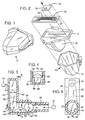
- Fig. 1 is a perspective view of an exemplary ink cartridge designed to incorporate the flow control unit of the present invention.
- Fig. 2 is an exploded perspective view of the cartridge of Fig. 1.
- Fig. 3 is a cross-sectional view of a flow control unit manufactured in accordance with the invention.
- Fig. 4 is a view taken along lines 4-4 of Fig.3.
- Fig. 5 is a view taken along lines 5-5 of Fig.3.
- the present invention involves an improved ink cartridge system which is characterized by a high degree of efficiency and minimal maintenance requirements.
- FIG. 1 An ink cartridge 10 usable in connection with the invention is illustrated in Fig. 1.
- This type of cartridge is manufactured by the Hewlett-Packard Company of Palo Alto, California.
- the cartridge 10 includes a housing 12, backing plate 14, and bladder-like ink reservoir 16.
- a substrate 20 with an ink feed hole 22 and thin film resistor pattern 23 thereon.
- an orifice plate 26 Secured to the substrate 20 as shown in Fig. 2 is an orifice plate 26 having drop expulsion holes 28 which communicate with the ink feed hole 22. Additional operating characteristics of this apparatus are presented in U. S. Patent 4,500,895 which is incorporated by reference.
- the invention as described herein is not limited to any specific type of ink cartridge or printing system. Instead, it may be used with any ink delivery/printing system having an ink reservoir maintained at a negative pressure.
- Control unit 40 includes an outer cover 42 and an ink feed orifice 44.
- the ink feed orifice 44 communicates with an ink printing/delivery system 45.
- the system 45 may take a variety of forms, including the resistor unit described above and discussed in U. S. Patent 4,500,895.
- control unit 40 is used in the cartridge 10 of Figs. 1 and 2, the substrate 20 could function as the outer cover 42. Likewise, the ink feed orifice 44 could operate as the ink feed hole 22 described above.
- the interior of the control unit 40 includes a first conduit 46 (commonly known is a standpipe) which is attached to an ink reservoir 47 maintained at a negative pressure. If the control unit 40 is used in the cartridge 10 of Figs. 1 and 2, the reservoir 47 may consist of the bladder-like structure 16 shown in Fig. 2.
- the control unit 40 also includes a second conduit 48 preferably consisting of a primary ink channel 49 which is circular in cross section as illustrated in Fig. 5, and having a diameter D1 (Fig. 3).
- the primary ink channel 49 communicates with a secondary ink channel 56 shown in Fig. 3.
- the primary ink channel 49 is positioned at a angle "X" of about 90 degrees relative to the secondary ink channel 56 (Fig. 3.)
- the secondary ink channel 56 has a height H1.
- the secondary ink channel 56 has a maximum width W1 at position 57 (Figs. 4-5.)
- the secondary ink channel 56 progressively decreases in width from position 57 toward ink feed orifice 44 due to the use of inwardly sloping side walls 58 illustrated in Figs. 4-5.
- a frustoconical medial section 62 Positioned between the primary ink channel 49 and the standpipe 46 is a frustoconical medial section 62 illustrated in Fig. 3.
- the medial section 62 has an opening 63 with a diameter progressively decreasing in the direction of reservoir 47.
- the opening 63 is surrounded by an annular, inwardly sloping interior wall 64.
- the opening 63 progressively decreases in diameter due to the inwardly sloping configuration of the wall 64.
- a spherical flow control member Positioned within the primary ink channel 49 is a spherical flow control member in the form of a ball 80.
- the ball 80 is preferably constructed of a material impervious to corrosion or reaction with ink.
- the ball 80 may be manufactured of a variety of materials including polypropylene plastic. It has a diameter D2 which is less than the diameter D1 of the primary ink channel 49. As a result, the ball 80 may freely move within the primary ink channel 49 (Fig. 3). Free, unencumbered movement of the ball 80 within the primary ink channel 49 is important. Accordingly, the primary ink channel 49 should be sufficiently large to allow the free movement of ball 80 therein whether the channel 49 is circular in cross section or not.
- the diameter D2 of the ball 80 is less than the width W1 (Fig.4), but greater than the height H1 (Fig. 3) of the secondary ink channel 56.
- This design prevents the ball 80 from passing out of the primary ink channel 49 into the secondary ink channel 56, as shown in dashed lines in Fig 3.
- ink is allowed to pass between channel 49 and channel 56 because the diameter D2 of the ball 80 is less than the width W1 of the secondary ink channel 56, as previously described and illustrated in Fig. 4.
- the ball 80 is larger than the opening 63 as shown in Fig. 3. This design prevents the ball 80 from passing through the medial section 62 into the standpipe 46, as described in greater detail below.
- ink is expelled from the cartridge using the printing/delivery system 45 which may take a variety of forms, as described above.
- ink flows by capillary action out of the reservoir 47 through the standpipe 46, medial section 62, primary ink channel 49, and secondary ink channel 56 prior to ejection.
- the ball 80 remains free-floating within the primary ink channel 49 due to the dimensional differences between the ball 80 and the primary ink channel 49 as previously described.
- the ball 80 assumes the position shown in dashed lines in Fig. 3.
- the negative pressure within the reservoir 47 causes air to enter the cartridge, ink will be displaced from the printing/delivery system.
- ink and air will begin moving in a reverse direction toward the reservoir 47.
- the ball 80 is moved by the ink toward and into the medial section 62. Since the ball 80 is larger than the opening 63 in the medial section 62, it will engage the wall 64 surrounding the opening 63 as shown in solid lines in Fig. 3. As a result, ink and air are prevented from flowing rearwardly into the standpipe 46 and reservoir 47, thereby minimizing the introduction of air into the reservoir and controlling deprimes.
- control unit 40 As described herein represents an important advance in the art of ink delivery. It offers superior results compared with the screen systems previously discussed. Moreover, the use of a free-floating, unencumbered ball 80 enables the ball 80 to be extremely responsive to minute directional changes in ink flow. As a result, the control unit 40 operates instantaneously, and offers minimal resistance to the outward flow of ink in comparison with other flow control systems.
Landscapes
- Health & Medical Sciences (AREA)
- Pain & Pain Management (AREA)
- Engineering & Computer Science (AREA)
- Bioinformatics & Cheminformatics (AREA)
- Biomedical Technology (AREA)
- Neurology (AREA)
- Neurosurgery (AREA)
- Chemical & Material Sciences (AREA)
- Chemical Kinetics & Catalysis (AREA)
- General Chemical & Material Sciences (AREA)
- Medicinal Chemistry (AREA)
- Nuclear Medicine, Radiotherapy & Molecular Imaging (AREA)
- Organic Chemistry (AREA)
- Pharmacology & Pharmacy (AREA)
- Life Sciences & Earth Sciences (AREA)
- Animal Behavior & Ethology (AREA)
- General Health & Medical Sciences (AREA)
- Public Health (AREA)
- Veterinary Medicine (AREA)
- Ink Jet (AREA)
Claims (5)
- Eine Flußsteuerungseinheit (40) zur Verwendung in einer Tintenkartusche, die ein Reservoir (47), das auf einem negativen Druck gehalten ist, in Verbindung mit einer Druckeinrichtung (45) zum Herausziehen der Tinte aus dem Reservoir (47) aufweist, mit:
einer ersten Röhre (46), die mit dem Reservoir (47) in Fluidverbindung ist;
einer zweiten Röhre (48), die zwischen der ersten Röhre (46) und der Druckeinrichtung (45) angeordnet ist und mit diesen in Fluidverbindung ist, wobei die zweite Röhre (48) einen primären Tintenkanal (49) und einen sekundären Tintenkanal (56), die miteinander in Fluidverbindung sind, umfaßt;
einem Mittelabschnitt (62), der zwischen der ersten Röhre (46) und der zweiten Röhre (48) angeordnet ist, wobei der Mittelabschnitt (62) eine Öffnung (63) zwischen der ersten Röhre (46) und dem primären Tintenkanal (49) der zweiten Röhre (48) definiert; und
einem sphärischen Tintenflußsteuerungsbauglied (80), das innerhalb des primären Tintenkanals (49) der zweiten Röhre (48) angeordnet ist, wobei das Steuerungsbauglied (80) einen Durchmesser hat, der größer ist als der der Öffnung (63), wobei der primäre Tintenkanal (49) der zweiten Röhre (48) ausreichend groß ist, um die freie Bewegung des Steuerungsbauglieds (80) darin zu ermöglichen, wobei der sekundäre Tintenkanal (58) eine Höhe (H₁), die kleiner ist als der Durchmesser des Steuerungsbauglieds (80), und eine Breite (W₁) hat, die größer ist als der Durchmesser des Steuerungsbauglieds (80), wobei der sekundäre Tintenkanal (56) ein Hindurchfließen der Tinte durch diesen ermöglicht, während der Durchgang des Steuerungsbauglieds (80) durch diesen verhindert wird, wobei das Steuerungsbauglied (80) ermöglicht, daß die Tinte aus dem Reservoir (47) durch die erste Röhre (46), den Mittelabschnitt (62) und die zweite Röhre (48) zu der Druckeinrichtung (45) nach außen fließt, während es den Rückfluß von Luft und Tinte in die Kartusche und das Reservoir (47) durch Blockieren der Öffnung (63) verhindert. - Eine Flußsteuerungseinheit (40) nach Anspruch 1, bei der die Öffnung (63) einen zunehmend abnehmenden Durchmesser aufweist.
- Eine Flußsteuerungseinheit (40) gemäß Anspruch 1 oder 2, bei der der primäre Tintenkanal (49) in einem Winkel von 90° relativ zu dem sekundären Tintenkanal (56) angeordnet ist.
- Eine Flußsteuerungseinheit (40) gemäß einem vorhergehenden Anspruch, bei dem das sphärische Tintenflußsteuerungsbauglied (80) aus Plastik besteht.
- Eine Flußsteuerungseinheit (40) gemäß irgendeinem vorhergehenden Anspruch, bei dem der Mittelabschnitt (62) eine ringförmige, nach innen gewinkelte Innenwand (56), die die Öffnung (63) definiert, umfaßt, wobei das sphärische Tintenflußsteuerungsbauglied (80) angepaßt ist, um mit der Wand (64) Eingriff zu nehmen, um die Öffnung (63) zu blockieren, um den Rückfluß von Luft und Tinte in die Kartusche und in das Reservoir (47) zu verhindern.
Applications Claiming Priority (2)
| Application Number | Priority Date | Filing Date | Title |
|---|---|---|---|
| US07/381,446 US4931812A (en) | 1989-07-18 | 1989-07-18 | Flow control system for ink cartridges |
| US381446 | 1989-07-18 |
Publications (2)
| Publication Number | Publication Date |
|---|---|
| EP0412643A1 EP0412643A1 (de) | 1991-02-13 |
| EP0412643B1 true EP0412643B1 (de) | 1994-09-21 |
Family
ID=23505049
Family Applications (1)
| Application Number | Title | Priority Date | Filing Date |
|---|---|---|---|
| EP90306809A Expired - Lifetime EP0412643B1 (de) | 1989-07-18 | 1990-06-21 | Durchflussregelungsanordnung für Tintenkartuschen |
Country Status (6)
| Country | Link |
|---|---|
| US (1) | US4931812A (de) |
| EP (1) | EP0412643B1 (de) |
| JP (1) | JP3034284B2 (de) |
| DE (1) | DE69012710T2 (de) |
| HK (1) | HK21695A (de) |
| SG (1) | SG162294G (de) |
Families Citing this family (37)
| Publication number | Priority date | Publication date | Assignee | Title |
|---|---|---|---|---|
| US5526030A (en) * | 1992-10-05 | 1996-06-11 | Hewlett-Packard Company | Pressure control apparatus for an ink pen |
| USD341156S (en) | 1990-03-26 | 1993-11-09 | Dataproducts Corporation | Ink jet ink cartridge |
| JPH04214360A (ja) * | 1990-12-10 | 1992-08-05 | Canon Inc | インクジェット記録装置,該装置用インクタンクカートリッジ、および該カートリッジの製造方法 |
| US5153612A (en) * | 1991-01-03 | 1992-10-06 | Hewlett-Packard Company | Ink delivery system for an ink-jet pen |
| US5920332A (en) * | 1993-05-04 | 1999-07-06 | Markem Corporation | Ink barrier for fluid reservoir vacuum or pressure line |
| US5600358A (en) * | 1993-06-30 | 1997-02-04 | Hewlett-Packard Company | Ink pen having a hydrophobic barrier for controlling ink leakage |
| US5369429A (en) * | 1993-10-20 | 1994-11-29 | Lasermaster Corporation | Continuous ink refill system for disposable ink jet cartridges having a predetermined ink capacity |
| US5606988A (en) * | 1994-02-04 | 1997-03-04 | Hewlett -Packard Company | Connector assembly for ink cartridge |
| US5742308A (en) * | 1994-03-30 | 1998-04-21 | Hewlett-Packard Company | Ink jet printer cartridge refilling method and apparatus |
| US5574489A (en) * | 1994-03-30 | 1996-11-12 | Hewlett-Packard Company | Ink cartridge system for ink-jet printer |
| JPH08174860A (ja) | 1994-10-26 | 1996-07-09 | Seiko Epson Corp | インクジェットプリンタ用インクカートリッジ |
| US6007190A (en) * | 1994-12-29 | 1999-12-28 | Encad, Inc. | Ink supply system for an ink jet printer having large volume ink containers |
| US5686947A (en) | 1995-05-03 | 1997-11-11 | Encad, Inc. | Ink jet printer incorporating high volume ink reservoirs |
| AU7502996A (en) * | 1995-11-08 | 1997-05-29 | American Ink Jet Corporation | Refilling ink jet cartridges |
| USD405465S (en) | 1996-01-16 | 1999-02-09 | Motorola, Inc. | Material sensor |
| JP3750138B2 (ja) | 1996-02-21 | 2006-03-01 | セイコーエプソン株式会社 | インクカートリッヂ |
| US5933175A (en) * | 1996-08-05 | 1999-08-03 | Hewlett-Packard Company | Bottom fill inkjet cartridge through bubble generator |
| US5901425A (en) | 1996-08-27 | 1999-05-11 | Topaz Technologies Inc. | Inkjet print head apparatus |
| US6003966A (en) * | 1997-02-28 | 1999-12-21 | Samsung Electronics Co., Ltd. | Device for sensing cartridge replacement time in a printer equipment using an inkjet injecting apparatus |
| JP4141523B2 (ja) | 1997-03-19 | 2008-08-27 | セイコーエプソン株式会社 | インク供給流路の弁装置 |
| EP1055520B1 (de) * | 1998-02-13 | 2003-10-01 | Seiko Epson Corporation | Tintenstrahldrucker, dafür geeignete tanktureinheit und verfahren zur wiederherstellung des tintentröpfchenausstossvermögens |
| ATE496775T1 (de) | 1998-07-15 | 2011-02-15 | Seiko Epson Corp | Tintenbehälter |
| US6176573B1 (en) | 1999-11-15 | 2001-01-23 | Agilent Technologies Inc. | Gas-flow management using capillary capture and thermal release |
| PT1199179E (pt) | 2000-10-20 | 2007-02-28 | Seiko Epson Kabushiki Kaisha S | Dispositivo de gravação a jacto de tinta e cartucho de tinta |
| KR100487976B1 (ko) | 2000-10-20 | 2005-05-10 | 세이코 엡슨 가부시키가이샤 | 잉크젯 기록 장치용 잉크 카트리지 |
| SG137690A1 (en) | 2000-10-20 | 2007-12-28 | Seiko Epson Corp | Ink-jet recording device and ink cartridge |
| JP3991853B2 (ja) | 2002-09-12 | 2007-10-17 | セイコーエプソン株式会社 | インクカートリッジ |
| US6799844B2 (en) * | 2002-12-16 | 2004-10-05 | Xerox Corporation | High shear ball check valve device and a liquid ink image producing machine using same |
| US7296881B2 (en) * | 2005-01-21 | 2007-11-20 | Hewlett-Packard Development Company, L.P. | Printhead de-priming |
| US7311389B1 (en) | 2005-02-09 | 2007-12-25 | Tarry Pidgeon | Ink maintenance system for ink jet cartridges |
| US7387376B2 (en) * | 2005-03-03 | 2008-06-17 | Fuji Xerox Co., Ltd. | Liquid droplet ejecting unit, image forming apparatus and valve |
| US20080006530A1 (en) * | 2006-06-19 | 2008-01-10 | Handani Winarta | Capillary Flow Control in a Flow Channel |
| US7771033B2 (en) * | 2007-02-16 | 2010-08-10 | Hewlett-Packard Development Company, L.P. | Printing device |
| EP3322590B1 (de) | 2015-07-14 | 2021-06-02 | Hewlett-Packard Development Company, L.P. | Materialstrahlkammer |
| US11207823B2 (en) | 2018-09-14 | 2021-12-28 | Makerbot Industries, Llc | Removable extruder cap |
| USD893568S1 (en) * | 2019-03-19 | 2020-08-18 | Makerbot Industries, Llc | Extruder cap |
| USD900179S1 (en) * | 2019-03-20 | 2020-10-27 | Makerbot Industries, Llc | Extruder for a three-dimensional printer |
Family Cites Families (8)
| Publication number | Priority date | Publication date | Assignee | Title |
|---|---|---|---|---|
| US4403229A (en) * | 1981-10-30 | 1983-09-06 | International Business Machines Corporation | Maintenance system to prime and to exclude air from ink jet heads |
| US4527175A (en) * | 1981-12-02 | 1985-07-02 | Matsushita Electric Industrial Company, Limited | Ink supply system for nonimpact printers |
| US4433341A (en) * | 1982-06-07 | 1984-02-21 | Ncr Corporation | Ink level control for ink jet printer |
| US4500895A (en) * | 1983-05-02 | 1985-02-19 | Hewlett-Packard Company | Disposable ink jet head |
| US4737801A (en) * | 1985-07-24 | 1988-04-12 | Canon Kabushiki Kaisha | Ink supply device and an ink jet recording apparatus having the ink supply device |
| US4677447A (en) * | 1986-03-20 | 1987-06-30 | Hewlett-Packard Company | Ink jet printhead having a preloaded check valve |
| EP0255687A3 (de) * | 1986-07-31 | 1989-04-26 | Siemens Aktiengesellschaft | Tintendruckeinrichtung mit austauschbarem, elektrothermische Wandler enthaltenden Druckkopf |
| US4714937A (en) * | 1986-10-02 | 1987-12-22 | Hewlett-Packard Company | Ink delivery system |
-
1989
- 1989-07-18 US US07/381,446 patent/US4931812A/en not_active Expired - Lifetime
-
1990
- 1990-06-21 EP EP90306809A patent/EP0412643B1/de not_active Expired - Lifetime
- 1990-06-21 DE DE69012710T patent/DE69012710T2/de not_active Expired - Fee Related
- 1990-07-18 JP JP2190374A patent/JP3034284B2/ja not_active Expired - Fee Related
-
1994
- 1994-11-10 SG SG162294A patent/SG162294G/en unknown
-
1995
- 1995-02-16 HK HK21695A patent/HK21695A/en not_active IP Right Cessation
Also Published As
| Publication number | Publication date |
|---|---|
| JPH0357652A (ja) | 1991-03-13 |
| JP3034284B2 (ja) | 2000-04-17 |
| DE69012710D1 (de) | 1994-10-27 |
| DE69012710T2 (de) | 1995-02-02 |
| SG162294G (en) | 1995-04-28 |
| EP0412643A1 (de) | 1991-02-13 |
| HK21695A (en) | 1995-02-24 |
| US4931812A (en) | 1990-06-05 |
Similar Documents
| Publication | Publication Date | Title |
|---|---|---|
| HK21695A (en) | Flow control system for ink cartridges | |
| US6481837B1 (en) | Ink delivery system | |
| JP3454446B2 (ja) | プリンタのインク送り出し方法 | |
| JP2945176B2 (ja) | インクジェットペン用のアキュムレータ | |
| US6773097B2 (en) | Ink delivery techniques using multiple ink supplies | |
| EP0704309A2 (de) | Verfahren und Einrichtung zur Tintenwiederauffüllung einer Tintenpatrone | |
| US6364471B1 (en) | Fluid accumulator for ink-jet print heads | |
| JPH10128993A5 (de) | ||
| JPH09131889A (ja) | インク・ジェットの軸外のインク送り出しシステム | |
| JPH03180357A (ja) | インクジェットペン | |
| US6120139A (en) | Ink flow design to provide increased heat removal from an inkjet printhead and to provide for air accumulation | |
| JP2002307712A (ja) | 圧力調整室およびこれを有するインクジェット記録ヘッド、これを用いたインクジェット記録装置 | |
| JP5951091B1 (ja) | ダンパー装置及びこれを備えた液体供給システム、並びにインクジェット式記録装置 | |
| US6003986A (en) | Bubble tolerant manifold design for inkjet cartridge | |
| US5917526A (en) | Method and apparatus for ink container locking | |
| GB2351945A (en) | Method and apparatus for adapting an ink jet printing system for receiving an alternate supply of ink | |
| US4422086A (en) | Device for feeding constant pressure fluid | |
| JPH11227223A (ja) | インク容器 | |
| JP2005028870A (ja) | プリントシステムに使用されるインク槽およびインク槽内の背圧を調整する方法 | |
| JPS62231760A (ja) | プリントヘツドへのインク供給装置 | |
| CA1175879A (en) | Ink jet printing method and apparatus | |
| KR102560001B1 (ko) | 배압 시스템을 갖는 잉크 저장조 | |
| EP2620286A1 (de) | Kontinuierliches Strahldrucken eines Flüssigmaterials | |
| JP4486967B2 (ja) | インキジェットプリントヘッド用の液体給送システム | |
| US7500737B2 (en) | Free flow fluid delivery system for printing device |
Legal Events
| Date | Code | Title | Description |
|---|---|---|---|
| PUAI | Public reference made under article 153(3) epc to a published international application that has entered the european phase |
Free format text: ORIGINAL CODE: 0009012 |
|
| AK | Designated contracting states |
Kind code of ref document: A1 Designated state(s): DE FR GB IT |
|
| 17P | Request for examination filed |
Effective date: 19910711 |
|
| 17Q | First examination report despatched |
Effective date: 19930308 |
|
| GRAA | (expected) grant |
Free format text: ORIGINAL CODE: 0009210 |
|
| AK | Designated contracting states |
Kind code of ref document: B1 Designated state(s): DE FR GB IT |
|
| REF | Corresponds to: |
Ref document number: 69012710 Country of ref document: DE Date of ref document: 19941027 |
|
| ET | Fr: translation filed | ||
| ITF | It: translation for a ep patent filed | ||
| PLBE | No opposition filed within time limit |
Free format text: ORIGINAL CODE: 0009261 |
|
| STAA | Information on the status of an ep patent application or granted ep patent |
Free format text: STATUS: NO OPPOSITION FILED WITHIN TIME LIMIT |
|
| 26N | No opposition filed | ||
| REG | Reference to a national code |
Ref country code: GB Ref legal event code: 732E |
|
| REG | Reference to a national code |
Ref country code: FR Ref legal event code: TP |
|
| REG | Reference to a national code |
Ref country code: GB Ref legal event code: IF02 |
|
| PGFP | Annual fee paid to national office [announced via postgrant information from national office to epo] |
Ref country code: FR Payment date: 20050617 Year of fee payment: 16 |
|
| PGFP | Annual fee paid to national office [announced via postgrant information from national office to epo] |
Ref country code: DE Payment date: 20050801 Year of fee payment: 16 |
|
| PGFP | Annual fee paid to national office [announced via postgrant information from national office to epo] |
Ref country code: IT Payment date: 20060630 Year of fee payment: 17 |
|
| PG25 | Lapsed in a contracting state [announced via postgrant information from national office to epo] |
Ref country code: DE Free format text: LAPSE BECAUSE OF NON-PAYMENT OF DUE FEES Effective date: 20070103 |
|
| REG | Reference to a national code |
Ref country code: FR Ref legal event code: ST Effective date: 20070228 |
|
| PGFP | Annual fee paid to national office [announced via postgrant information from national office to epo] |
Ref country code: GB Payment date: 20070628 Year of fee payment: 18 |
|
| PG25 | Lapsed in a contracting state [announced via postgrant information from national office to epo] |
Ref country code: FR Free format text: LAPSE BECAUSE OF NON-PAYMENT OF DUE FEES Effective date: 20060630 |
|
| GBPC | Gb: european patent ceased through non-payment of renewal fee |
Effective date: 20080621 |
|
| PG25 | Lapsed in a contracting state [announced via postgrant information from national office to epo] |
Ref country code: GB Free format text: LAPSE BECAUSE OF NON-PAYMENT OF DUE FEES Effective date: 20080621 |
|
| PG25 | Lapsed in a contracting state [announced via postgrant information from national office to epo] |
Ref country code: IT Free format text: LAPSE BECAUSE OF NON-PAYMENT OF DUE FEES Effective date: 20070621 |