EP0412320B1 - Méthode de transmission de données au moyen de télégrammes d'impulsions entre des postes d'abonnés d'un dispositif de télétraitement et circuit pour mettre en oeuvre la méthode - Google Patents
Méthode de transmission de données au moyen de télégrammes d'impulsions entre des postes d'abonnés d'un dispositif de télétraitement et circuit pour mettre en oeuvre la méthode Download PDFInfo
- Publication number
- EP0412320B1 EP0412320B1 EP90113585A EP90113585A EP0412320B1 EP 0412320 B1 EP0412320 B1 EP 0412320B1 EP 90113585 A EP90113585 A EP 90113585A EP 90113585 A EP90113585 A EP 90113585A EP 0412320 B1 EP0412320 B1 EP 0412320B1
- Authority
- EP
- European Patent Office
- Prior art keywords
- signal
- data
- transmission
- circuit arrangement
- signals
- Prior art date
- Legal status (The legal status is an assumption and is not a legal conclusion. Google has not performed a legal analysis and makes no representation as to the accuracy of the status listed.)
- Expired - Lifetime
Links
Images

Classifications
-
- H—ELECTRICITY
- H04—ELECTRIC COMMUNICATION TECHNIQUE
- H04L—TRANSMISSION OF DIGITAL INFORMATION, e.g. TELEGRAPHIC COMMUNICATION
- H04L1/00—Arrangements for detecting or preventing errors in the information received
- H04L1/22—Arrangements for detecting or preventing errors in the information received using redundant apparatus to increase reliability
Definitions
- the invention relates to a method as specified in the preamble of claim 1 and a circuit arrangement for carrying out the method.
- a signal collecting device with an arrangement for querying signal transmitters by means of a central query device which cyclically calls the signal transmitters is already known from DE-OS 34 36 414.
- the known arrangement is designed for central monitoring of the operation of transmission devices and is particularly suitable for devices for the automatic management of long-distance systems.
- the signals are transferred to a computer serially, bit or byte as pulse trains.
- FIG DE-OS 26 29 499 An arrangement for the selection of two transmission paths carrying the same digital signal, in which a selection of one of two transmission paths carrying the same signal is provided at the receiving end, is already shown in FIG DE-OS 26 29 499 known.
- a first signaling device for exceeding a defined bit error rate, a second signaling device for an AIS signal (alarm indication signal) and a third signaling device for digital signal failure are provided on each transmission link.
- a changeover switch connects the selected transmission path with an output.
- Logic controlled by the signaling devices controls the switch.
- the reliability of data transmission between signal collectors could be significantly increased compared to transmission over a single transmission channel.
- quality criteria of layer 1 would be obtained and used for the selection of the better transmission path.
- a digital signal transmission system with line replacement mode in which a receiving device is connected to a transmitting device via a first and a second transmission path.
- the data signal supplied by a data source is divided into data blocks in each transmitter. At least one check bit is added to each data block.
- the digital signal thus supplemented arrives in the associated receiver.
- There is an error checking device in each receiver which emits an error signal if a bit error has occurred in the associated data block.
- a control device controls the changeover switch so that when an error signal occurs, the changeover is made to the other transmission path.
- the object of the invention is to provide a method for transmitting data by means of pulse telegrams between subscriber stations of a telecontrol device, which ensures the most reliable possible transmission of the data and is suitable for various types of digital transmission channels.
- the task is performed by the in the characterizing part of Claim 1 specified method steps solved.
- the selection of one of the two received signals can be carried out with the aid of a switch connected upstream of the microcomputer system or in the microcomputer system itself.
- the subscriber stations of the remote control device are, in particular, signal collectors or alarm collectors of a signal or alarm collection device.
- the measures according to the invention advantageously result A particularly secure transmission of the information to be exchanged between the subscriber stations, without this requiring any noteworthy additional outlay on circuit means.
- Another important advantage is that the method can be easily adapted to different types of transmission links and places comparatively low demands on the monitoring options of the relevant transmission link itself.
- the information about the state of at least the selected transmission link and at least one time criterion are linked to one another.
- the failure criteria of layer 1 take effect immediately or after a specified buffer time in order to be able to obtain a clearly secured fault status and thus avoid switching over in the event of brief faults.
- Quality criteria are won in layer 2.
- a criterion can be the ratio of the number of disturbed telegrams to the total number of telegrams in a given period of time.
- a useful circuit arrangement for carrying out the method is set out in claim 3.
- a data input is expediently provided in connection with a selection of the received signal by a changeover switch connected upstream of the microcomputer system, and two data inputs are provided when the microcomputer system is selected.
- the data is transmitted using the HDLC protocol.
- the data for the HDLC protocol are encoded in NRZI format.
- the idle state i.e. between the telegrams, expediently sent permanent flags.
- the measures according to claim 5 have the advantage that the monitoring properties of the HDLC controller are also used to obtain the switchover criterion.
- the preferred monitoring signals of OSI layer 1 are specified for two preferred types of transmission links.
- the method according to the invention is suitable for various types of digital transmission paths, it is advantageously possible, in accordance with claim 8, to design a unit containing the circuit arrangement for connecting the signal transmitters to various types of transmission channels in such a way that their basic structure is the same and in particular with regard to the transmitter and receiver can be optionally equipped.
- the signal collectors optionally have a two-way connection for the G.703 interface according to CCITT for 64 Kbit / s or for the V.11 interface according to CCITT.
- the periodic switchover therefore only takes place if there are no fault messages from layer 1 for both transmission channels.
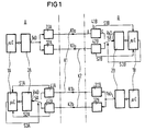
- microcomputer system 1A In the circuit arrangement shown in FIG. 1, data is exchanged between the microcomputer systems 1A and 1B.
- the microcomputer system 1A is arranged in the operating point A, the microcomputer system 1B in the operating point B.
- Both microcomputer systems 1A and 1B are signal collectors of a signal collecting device, with the aid of which signals are collected for central operational monitoring.
- Both signal collectors or microcomputer systems 1A and 1B exchange information with one another via the two four-wire transmission channels K1 and K2.
- the data is transmitted in both directions in the same way with the aid of similar transmission, monitoring and processing means. It is therefore sufficient to describe the circuit arrangement for one of the two transmission directions.
- the structure and function of the other direction of transmission result from the fact that in the description of the direction of transmission A, B in the reference numerals the "A" is replaced by a "B” and the "B” by an "A".
- the microcomputer system 1A of the operating point A is led with its signal output to the HDLC controller 2A.
- the output TxD of the HDLC controller 2A is routed both to the signal input of the transmitter 31A and to the signal input of the transmitter 32A.
- the transmitter 31A is routed via one direction of the transmission channel K1 to the receiver 41B of the operating point B, the signal output of the transmitter 32A via the one direction of the transmission channel K2 to the receiver 42B of the operating point B.
- the input RxD of the HDLC controller 2B can optionally be connected to the output of the receiver 41B or the receiver 42B.
- FIG. 2 shows a modification of the circuit arrangement according to FIG. 1, in which the selection of the received data in operating point B is not carried out with the aid of the switch shown in FIG 5B, but with the help of the microcomputer system 1B itself.
- each of the two receivers 41B and 42B is followed by its own HDLC controller 2B1 or 2B2.
- Each of these two HDLC controllers 2B1 and 2B2 has its output routed to the microcomputer system 1B via its own connection. In this case, the quality criteria of layer 2 of both reception channels in the microcomputer system can be compared and evaluated.
- the circuit arrangement shown in FIG. 1 is used to transmit data telegrams, with the aid of which the microcomputers belonging to signal collectors exchange information.
- the data is transmitted between operating points A and B, in particular via digital signal channels at 64 kbit / s. Also advantageous is the transmission via freely usable bits of digital signal transmission systems, in particular bits (Y bits, N bits) of digital signal multiplex devices reserved for national use, in particular with 0.6 ... 19.2 kbit / s using the V.11 interface mentioned. Furthermore, a transfer using free bytes in devices of the synchronous digital hierarchy can be expedient.
- the interfaces of the signal collectors 1A and 1B are equipped for the transmission of the data via two transmission channels, preferably for a two-way guide, and are provided with automatic switching devices.
- FIG. 1 shows a circuit arrangement for two-way data transmission between the signal collecting devices of operating point A and operating point B.
- the sending and receiving directions are shown separately.
- the function blocks shown separately but with the same names each represent a unit, for example the HDLC controller 2A or 2B is in each case an IC.
- the sending direction of operating point A and operating point B have the same structure, as does the receiving direction of the two stations.
- the signal collectors each have their own receiver for each route with a monitoring device that emits a signal if the transmission channel fails.
- the HDLC controller 2A sends the telegram from the output TxD via the two transmitters 31A and 32A to the transmission channel Kla route 1 and route K2a.
- the receivers 41B and 42B receive the data, their signal transmitters for the signals S1B and S2B do not respond.
- the switch 5B is randomly connected to the receiver 4B, the output of which is thus connected to the data input RxD of the HDLC controller 2B.
- the microcomputer system 1B then initiates the switch to the path K1a after corresponding further evaluations and query of time criteria via the switching signal S3B. A further changeover then takes place only after an interruption in the path K1a.
- the HDLC controller 2B transfers status data about reception errors to the microcomputer system 1B with each received telegram.
- the microcomputer system 1B forms information about the quality of the relevant transmission channel by integration. The quality can be monitored for both channels by regular switching with the help of the switch 5B. Switching is controlled by time criteria, each in a time gap between two telegrams. It is therefore not switched over during a telegram, so that it is retained.
- the direction of return of the transmission channel shown below in FIG. 1 has a mirror-like design and is also completely identical in function.
- the digital signal channels expediently have G.703 interfaces.
- the transmitters 31A to 32B in this case are G.703 interface converters.
- the signals S1A to S2B are messages KDS, i.e. "no digital signal” and AIS.
- the two-way data transmission can be carried out via V.11 interfaces between the signal collection devices of site A and site 8. Different transmission devices can be looped into each of the two ways via the V.11 interfaces. It is thus possible in particular to use the 34/140 Mbit / s Y-bit or N-bit of the digital transmission system reserved for national use for data transmission.
- the transmitters 31A to 32B are V.11 interface converters in this case.
- the signals S1A to S2B are messages KDS. There are no AIS signals.
- CMOS interfaces of the data inputs and outputs of the HDLC controller to the 64 kbit / s interfaces in accordance with CCITT recommendation G.703 can serve as an LSI module.
- This block includes realized the monitoring functions "detection of a failure of the incoming digital signal" "detection of an AIS signal”. Both functions are linked via an OR gate and fed to the microcomputer system for evaluation.
- an additional monitoring circuit forms this signal by evaluating the signal changes. For this it is necessary that signal changes occur on the transmission channel in the pauses between the telegrams. This can be achieved by sending permanent flags in the breaks.
- An edge-triggered retriggerable monostable multivibrator or a counter circuit according to FIG. 3 is triggered by the signal change of the received data. If the received data fails, it falls into the rest position, which corresponds to the "path disturbed" state.
- FIG. 3 shows an embodiment for a V.11 receiver with monitoring device.
- the connections of this receiver are designated as a, b and c in FIG.
- the diodes 67 and 68 serve to protect the input against overvoltage.
- the monitoring circuit is formed from components 61-66. It works as a flank-triggered retriggerable monostable multivibrator.
- a negative pulse is formed from each negative edge in the bit stream at the input of the Schmitt trigger 66, which outputs a positive reset pulse to the counter 62. If the data stream or the idle flags are interrupted, the reset pulses are omitted, the 2 Hz clock at the input of the OR gate 61 switches the counter 62 on until its output QD is at log. "1" switches, the OR gate 61 blocks the 2 Hz clock and emits the "path disturbed" signal.
- Figure 4 shows the processing of the various input information to form the switchover signal.
- the signals KDS1 / AIS1 and KDS2 / AIS2 (OSI layer 1) as well as status information of the HDLC controller (OSI layer 2) are processed.
- the telegram errors are transferred from the HDLC controller as status information and added up in the microcomputer system 1B and evaluated per unit of time.
- the quality of the two transmission channels can thus be determined and the better channel selected for the transmission.
Landscapes
- Engineering & Computer Science (AREA)
- Computer Networks & Wireless Communication (AREA)
- Signal Processing (AREA)
- Maintenance And Management Of Digital Transmission (AREA)
- Time-Division Multiplex Systems (AREA)
- Selective Calling Equipment (AREA)
- Communication Control (AREA)
Claims (12)
- Procédé pour transmettre des données au moyen de télégrammes d'impulsions entre des unités de collecte de signaux d'un dispositif de collecte de signaux, qui sont disposées dans des postes de service (A,B), qui sont éloignés les uns des autres, d'un dispositif de transmission de signaux numériques, et à l'aide desquels des signaux sont collectés pour une observation centralisée du fonctionnement, les postes d'abonnés étant reliés entre eux par l'intermédiaire de sections numériques de transmission d'informations qui contiennent des émetteurs et des récepteurs pour émettre et recevoir des signaux numériques, caractérisé par le fait que dans au moins un sens de transmission, les données, qui doivent être transmises entre les unités de collecte des signaux, sont transmises simultanément par l'intermédiaire de deux sections de transmission (K1,K2), et qu'à l'aide d'un dispositif de sélection, l'une des deux sections de transmission (K1,K2) est sélectionnée pour la transmission des données, et que les données transmises par la section de transmission sélectionnée sont traitées par un système à micro-ordinateur (1A,1B), qui est branché en aval des récepteurs et est associé à l'unité de collecte de signaux, et que des signaux de contrôle des deux sections de transmission sont envoyés, par les dispositifs de contrôle associés aux récepteurs, au système à micro-ordinateur en vue d'être évalués, et que le système à micro-ordinateur (1A,1B) établit, à partir des données reçues, des informations propres concernant l'état au moins de la section de transmission sélectionnée respective et combine entre eux les signaux de contrôle, qui appartiennent aux deux sections de transmission, et les informations obtenues à partir des données reçues concernant l'état au moins de la section de transmission respectivement sélectionnée, et qu'à partir du résultat de la combinaison est formé un signal de commande (S3, S3A, S3B), qui détermine la sélection de l'un des deux signaux de réception.
- Procédé suivant la revendication 1, caractérisé par le fait que les informations obtenues à partir des données reçues et concernant l'état au moins de la section de transmission sélectionnée sont combinées à au moins un critère de temps.
- Montage pour la transmission de données au moyen de télégrammes d'impulsions entre des unités de collecte de signaux d'un dispositif de collecte de signaux, qui sont disposées en des emplacements de fonctionnement (A,B), qui sont éloignés les uns des autres, d'un dispositif de transmission de signaux numériques, et à l'aide desquels des signaux sont collectés pour une observation centralisée du fonctionnement, les postes d'abonnés étant reliés entre eux par l'intermédiaire de sections numériques de transmission d'informations qui contiennent des émetteurs et des récepteurs pour émettre et recevoir des signaux numériques, pour la mise en oeuvre du procédé suivant la revendication 1 ou 2,
caractérisé par le fait que dans au moins un sens de transmission, un poste de service (A,B) contient deux émetteurs pour l'émission de données par l'intermédiaire de deux sections de transmission, que dans l'autre poste de service (B,A), les sorties des signaux des deux récepteurs sont reliées, au moyen d'un dispositif de sélection, à un système à micro-ordinateur (1A,1B) associé à l'unité de collecte des signaux et qui sert à traiter les données transmises par la section de transmission sélectionnée et qu'aux récepteurs sont associés des dispositifs de contrôle servant à obtenir des signaux de contrôle des deux sections de transmission, que le système à micro-ordinateur (1A,1B) est raccordé aux sorties de signaux de contrôle des dispositifs de contrôle et qu'on obtient des informations particulières concernant l'état au moins de respectivement la section de transmission sélectionnée sont obtenues à partir des données reçues, et combine entre eux les signaux de contrôle, qui appartiennent aux deux sections de transmission, et les informations obtenues à partir des données reçues et concernant l'état au moins de la section de transmission respectivement sélectionnée et qu'à partir du résultat de la combinaison est formé un signal de commande (S3,S3A,S3B), à l'aide duquel le dispositif de sélection peut être commandé. - Montage suivant la revendication 3, caractérisé par le fait qu'en amont des deux émetteurs est branché un dispositif de commande HDLC (2A,2B) et que sur le côté réception, respectivement un dispositif de commande HDLC (2A, 2B) convenant pour la transmission de drapeaux de durée, est branché en amont de l'entrée de données ou de deux entrées de données du système à micro-ordinateur.
- Montage suivant la revendication 3 ou 4, caractérisé par le fait que pour la transmission des données, on utilise des canaux numériques possédant une cadence binaire de 64 kbits/s, et que les récepteurs des dispositifs de contrôle contiennent les dispositifs de réception pour la réception ou la non-réception de signaux numériques pouvant être évalués et pour la réception ou la non-réception d'un signal AIS, et possèdent un dispositif de signalisation pour la signalisation "aucun signal numérique" et un dispositif de signalisation pour la signalisation "signal AIS", et que le système à micro-ordinateur est raccordé aux deux sorties de signalisation.
- Montage suivant la revendication 4, caractérisé par le fait que pour la transmission des données, on utilise les bits, réservés pour une utilisation nationale, de signaux de multiplexage numériques et que le dispositif de contrôle contient un étage à bascule monostable redéclenchable, qui est déclenché par les flancs des impulsions et qui contrôle le sens de réception de la voie de transmission associée pour déterminer s'il se produit un changement de l'état "1" à l'état "0" et/ou un changement de l'état "0" à l'état "1", et, en cas d'absence de ce changement, produit la signalisation "aucun signal numérique".
- Montage suivant la revendication 6, caractérisé par le fait que dans l'état de repos, des drapeaux permanents sont émis dans les canaux de transmission (K1,K2).
- Montage suivant la revendication 6 ou 7, caractérisé par le fait qu'une unité de construction contenant le montage peut être équipée au choix d'un dispositif de raccordement à deux voies pour une interface à 64 kbits/s ou pour une interface pour des bits réservés d'une utilisation nationale.
- Montage suivant l'une des revendications 3 à 7, caractérisé par le fait qu'entre les sorties de données des deux récepteurs (41A,42A,41B,42B) et le système à micro-ordinateur (1A,1B) est disposé un commutateur (5A,5B) à l'aide duquel l'un des deux récepteurs peut être relié au système de micro-ordinateur.
- Montage suivant l'une des revendications 2 à 6, caractérisé par le fait que le dispositif de commande HDLC (2A,2B) transmet au micro-ordinateur des données d'état concernant des perturbations de réception et le système à micro-ordinateur forme à partir de là, notamment par intégration, des informations concernant la qualité du canal de transmission considéré.
- Montage suivant la revendication 8, caractérisé par le fait que les deux canaux sont contrôlés au moyen d'une commutation régulière du commutateur (5A,5B) pendant les pauses entre les télégrammes.
- Montage suivant l'une des revendications précédentes, caractérisé par le fait que les deux canaux de transmission (K1,K2) sont raccordés au système à micro-ordinateur (1A,1B), par l'intermédiaire d'un contrôleur HDLC particulier respectif.
Applications Claiming Priority (2)
| Application Number | Priority Date | Filing Date | Title |
|---|---|---|---|
| EP89114578 | 1989-08-07 | ||
| EP89114578 | 1989-08-07 |
Publications (2)
| Publication Number | Publication Date |
|---|---|
| EP0412320A1 EP0412320A1 (fr) | 1991-02-13 |
| EP0412320B1 true EP0412320B1 (fr) | 1994-11-30 |
Family
ID=8201731
Family Applications (1)
| Application Number | Title | Priority Date | Filing Date |
|---|---|---|---|
| EP90113585A Expired - Lifetime EP0412320B1 (fr) | 1989-08-07 | 1990-07-16 | Méthode de transmission de données au moyen de télégrammes d'impulsions entre des postes d'abonnés d'un dispositif de télétraitement et circuit pour mettre en oeuvre la méthode |
Country Status (3)
| Country | Link |
|---|---|
| EP (1) | EP0412320B1 (fr) |
| AT (1) | ATE114907T1 (fr) |
| DE (1) | DE59007822D1 (fr) |
Families Citing this family (3)
| Publication number | Priority date | Publication date | Assignee | Title |
|---|---|---|---|---|
| DE69635095T2 (de) * | 1995-05-23 | 2006-05-18 | Koninklijke Philips Electronics N.V. | Redundantes Datenübertragungssystem mit mindestens zwei Kanälen |
| EP0779722A1 (fr) * | 1995-12-11 | 1997-06-18 | Hewlett-Packard Company | Procédé de détection de pannes d'un canal de communication avec des voies de transmission redondantes |
| FR2748170B1 (fr) * | 1996-04-25 | 1998-07-03 | France Telecom | Dispositif de commutation automatique de lignes de transmission |
Family Cites Families (3)
| Publication number | Priority date | Publication date | Assignee | Title |
|---|---|---|---|---|
| DE2629499C2 (de) * | 1976-06-30 | 1981-10-15 | Siemens AG, 1000 Berlin und 8000 München | Umschalteeinrichtung zur Umschaltung einer Nachrichtenverbindung von einer ersten auf eine zweite !bertragungsstrecke |
| DE3145893C2 (de) * | 1981-11-19 | 1983-10-06 | Siemens Ag, 1000 Berlin Und 8000 Muenchen | Anordnung zur Auswahl einer von zwei das gleiche Digitalsignal führenden Übertragungsstrecken |
| DE3800977A1 (de) * | 1988-01-15 | 1989-07-27 | Ant Nachrichtentech | Digitalsignal-uebertragungssystem mit linienersatzbetrieb |
-
1990
- 1990-07-16 AT AT90113585T patent/ATE114907T1/de not_active IP Right Cessation
- 1990-07-16 DE DE59007822T patent/DE59007822D1/de not_active Expired - Fee Related
- 1990-07-16 EP EP90113585A patent/EP0412320B1/fr not_active Expired - Lifetime
Also Published As
| Publication number | Publication date |
|---|---|
| DE59007822D1 (de) | 1995-01-12 |
| EP0412320A1 (fr) | 1991-02-13 |
| ATE114907T1 (de) | 1994-12-15 |
Similar Documents
| Publication | Publication Date | Title |
|---|---|---|
| EP1062787B1 (fr) | Reseau local, notamment reseau ethernet, ayant des proprietes de redondance et un gestionnaire de redondance | |
| EP1476988B1 (fr) | Reseau local, en particulier reseau ethernet presentant des proprietes de redondance et gestionnaire de redondance destine a un reseau de ce type | |
| EP0335917A1 (fr) | Procede de localisation de stations defectueuses dans des reseaux locaux et commande d'interfaces correspondante. | |
| DE3642141A1 (de) | Verfahren zur dezentralen netzersatzschaltung | |
| EP2634973A1 (fr) | Appareil de communication pour un réseau de communication industriel fonctionnant de manière redondante et procédé de fonctionnement d'un appareil de communication | |
| EP0176015B1 (fr) | Procédé pour la transmission d'informations supplémentaires au moyen d'un canal numérique auxiliaire et utilisation du procédé | |
| EP0052390A1 (fr) | Procédé pour maintenir l'aptitude au fonctionnement d'un dispositif de transmission d'informations numériques et son application | |
| DE3603358C3 (de) | Verfahren und Einrichtung zur Datenübertragung in der Fernwirktechnik | |
| DE3418084C2 (fr) | ||
| EP0240833B1 (fr) | Dispositif de surveillance pour la surveillance du fonctionnement de dispositifs de transmission de la technique de transmission d'informations | |
| DE3139960C2 (fr) | ||
| EP0412320B1 (fr) | Méthode de transmission de données au moyen de télégrammes d'impulsions entre des postes d'abonnés d'un dispositif de télétraitement et circuit pour mettre en oeuvre la méthode | |
| DE3420365C2 (fr) | ||
| EP1476987B1 (fr) | Reseau local, en particulier reseau ethernet presentant des proprietes de redondance et appareil de couplage destine a un reseau de ce type | |
| DE4031241C2 (fr) | ||
| EP0106985B1 (fr) | Surveillance d'exploitation de voies de transmission numériques | |
| DE3742118C2 (fr) | ||
| DE10206068B4 (de) | System zur Übertragung von digitalen Daten zwischen Komponenten eines Steuerungssystems | |
| EP0193835B1 (fr) | Dispositif de rassemblement d'informations de surveillance dans des systèmes de transmission | |
| DE4000921C2 (fr) | ||
| EP0521253A2 (fr) | Méthode pour la communication bidirectionnelle de données | |
| EP0475135B1 (fr) | Système de transmission pour réseau de connection dans des reseaux de communication | |
| EP0974215A2 (fr) | Liaison de communication de donnees dans un reseau de communication hierarchique a bus, fonctionnant selon un protocole demande/reponse, a savoir selon le "protocole d'appel selectif" | |
| EP0392246B1 (fr) | Système de surveillance et de commande pour systèmes de transmission d'informations numériques avec maître et maître de substitution | |
| DE2928492A1 (de) | Verfahren und einrichtung zur ueberwachung von mehrere stationen verbindende leitungen, insbesondere in fernwirkmaschennetzen |
Legal Events
| Date | Code | Title | Description |
|---|---|---|---|
| PUAI | Public reference made under article 153(3) epc to a published international application that has entered the european phase |
Free format text: ORIGINAL CODE: 0009012 |
|
| AK | Designated contracting states |
Kind code of ref document: A1 Designated state(s): AT BE CH DE DK ES FR GB GR IT LI NL SE |
|
| 17P | Request for examination filed |
Effective date: 19901220 |
|
| 17Q | First examination report despatched |
Effective date: 19930519 |
|
| GRAA | (expected) grant |
Free format text: ORIGINAL CODE: 0009210 |
|
| AK | Designated contracting states |
Kind code of ref document: B1 Designated state(s): AT BE CH DE DK ES FR GB GR IT LI NL SE |
|
| PG25 | Lapsed in a contracting state [announced via postgrant information from national office to epo] |
Ref country code: NL Effective date: 19941130 Ref country code: GR Free format text: LAPSE BECAUSE OF FAILURE TO SUBMIT A TRANSLATION OF THE DESCRIPTION OR TO PAY THE FEE WITHIN THE PRESCRIBED TIME-LIMIT Effective date: 19941130 Ref country code: ES Free format text: THE PATENT HAS BEEN ANNULLED BY A DECISION OF A NATIONAL AUTHORITY Effective date: 19941130 Ref country code: DK Effective date: 19941130 |
|
| REF | Corresponds to: |
Ref document number: 114907 Country of ref document: AT Date of ref document: 19941215 Kind code of ref document: T |
|
| REF | Corresponds to: |
Ref document number: 59007822 Country of ref document: DE Date of ref document: 19950112 |
|
| ITF | It: translation for a ep patent filed |
Owner name: STUDIO JAUMANN |
|
| PG25 | Lapsed in a contracting state [announced via postgrant information from national office to epo] |
Ref country code: SE Effective date: 19950228 |
|
| GBT | Gb: translation of ep patent filed (gb section 77(6)(a)/1977) |
Effective date: 19950208 |
|
| ET | Fr: translation filed | ||
| NLV1 | Nl: lapsed or annulled due to failure to fulfill the requirements of art. 29p and 29m of the patents act | ||
| PLBE | No opposition filed within time limit |
Free format text: ORIGINAL CODE: 0009261 |
|
| STAA | Information on the status of an ep patent application or granted ep patent |
Free format text: STATUS: NO OPPOSITION FILED WITHIN TIME LIMIT |
|
| PGFP | Annual fee paid to national office [announced via postgrant information from national office to epo] |
Ref country code: CH Payment date: 19951017 Year of fee payment: 6 |
|
| 26N | No opposition filed | ||
| PGFP | Annual fee paid to national office [announced via postgrant information from national office to epo] |
Ref country code: GB Payment date: 19960621 Year of fee payment: 7 Ref country code: AT Payment date: 19960621 Year of fee payment: 7 |
|
| PGFP | Annual fee paid to national office [announced via postgrant information from national office to epo] |
Ref country code: BE Payment date: 19960717 Year of fee payment: 7 |
|
| PGFP | Annual fee paid to national office [announced via postgrant information from national office to epo] |
Ref country code: FR Payment date: 19960719 Year of fee payment: 7 |
|
| PG25 | Lapsed in a contracting state [announced via postgrant information from national office to epo] |
Ref country code: LI Effective date: 19960731 Ref country code: CH Effective date: 19960731 |
|
| REG | Reference to a national code |
Ref country code: CH Ref legal event code: PL |
|
| PG25 | Lapsed in a contracting state [announced via postgrant information from national office to epo] |
Ref country code: GB Free format text: LAPSE BECAUSE OF NON-PAYMENT OF DUE FEES Effective date: 19970716 Ref country code: AT Free format text: LAPSE BECAUSE OF NON-PAYMENT OF DUE FEES Effective date: 19970716 |
|
| PG25 | Lapsed in a contracting state [announced via postgrant information from national office to epo] |
Ref country code: BE Free format text: LAPSE BECAUSE OF NON-PAYMENT OF DUE FEES Effective date: 19970731 |
|
| PGFP | Annual fee paid to national office [announced via postgrant information from national office to epo] |
Ref country code: DE Payment date: 19970918 Year of fee payment: 8 |
|
| BERE | Be: lapsed |
Owner name: SIEMENS A.G. Effective date: 19970731 |
|
| GBPC | Gb: european patent ceased through non-payment of renewal fee |
Effective date: 19970716 |
|
| PG25 | Lapsed in a contracting state [announced via postgrant information from national office to epo] |
Ref country code: FR Free format text: LAPSE BECAUSE OF NON-PAYMENT OF DUE FEES Effective date: 19980331 |
|
| REG | Reference to a national code |
Ref country code: FR Ref legal event code: ST |
|
| PG25 | Lapsed in a contracting state [announced via postgrant information from national office to epo] |
Ref country code: DE Free format text: LAPSE BECAUSE OF NON-PAYMENT OF DUE FEES Effective date: 19990501 |
|
| PG25 | Lapsed in a contracting state [announced via postgrant information from national office to epo] |
Ref country code: IT Free format text: LAPSE BECAUSE OF NON-PAYMENT OF DUE FEES;WARNING: LAPSES OF ITALIAN PATENTS WITH EFFECTIVE DATE BEFORE 2007 MAY HAVE OCCURRED AT ANY TIME BEFORE 2007. THE CORRECT EFFECTIVE DATE MAY BE DIFFERENT FROM THE ONE RECORDED. Effective date: 20050716 |