EP0409822B1 - An adapter for brain surgery - Google Patents
An adapter for brain surgery Download PDFInfo
- Publication number
- EP0409822B1 EP0409822B1 EP87900146A EP87900146A EP0409822B1 EP 0409822 B1 EP0409822 B1 EP 0409822B1 EP 87900146 A EP87900146 A EP 87900146A EP 87900146 A EP87900146 A EP 87900146A EP 0409822 B1 EP0409822 B1 EP 0409822B1
- Authority
- EP
- European Patent Office
- Prior art keywords
- adapter
- imaging
- slide
- transducer
- frame
- Prior art date
- Legal status (The legal status is an assumption and is not a legal conclusion. Google has not performed a legal analysis and makes no representation as to the accuracy of the status listed.)
- Expired - Lifetime
Links
Images


Classifications
-
- A—HUMAN NECESSITIES
- A61—MEDICAL OR VETERINARY SCIENCE; HYGIENE
- A61B—DIAGNOSIS; SURGERY; IDENTIFICATION
- A61B8/00—Diagnosis using ultrasonic, sonic or infrasonic waves
- A61B8/42—Details of probe positioning or probe attachment to the patient
- A61B8/4209—Details of probe positioning or probe attachment to the patient by using holders, e.g. positioning frames
-
- A—HUMAN NECESSITIES
- A61—MEDICAL OR VETERINARY SCIENCE; HYGIENE
- A61B—DIAGNOSIS; SURGERY; IDENTIFICATION
- A61B8/00—Diagnosis using ultrasonic, sonic or infrasonic waves
- A61B8/08—Clinical applications
- A61B8/0808—Clinical applications for diagnosis of the brain
-
- A—HUMAN NECESSITIES
- A61—MEDICAL OR VETERINARY SCIENCE; HYGIENE
- A61B—DIAGNOSIS; SURGERY; IDENTIFICATION
- A61B90/00—Instruments, implements or accessories specially adapted for surgery or diagnosis and not covered by any of the groups A61B1/00 - A61B50/00, e.g. for luxation treatment or for protecting wound edges
- A61B90/10—Instruments, implements or accessories specially adapted for surgery or diagnosis and not covered by any of the groups A61B1/00 - A61B50/00, e.g. for luxation treatment or for protecting wound edges for stereotaxic surgery, e.g. frame-based stereotaxis
- A61B90/11—Instruments, implements or accessories specially adapted for surgery or diagnosis and not covered by any of the groups A61B1/00 - A61B50/00, e.g. for luxation treatment or for protecting wound edges for stereotaxic surgery, e.g. frame-based stereotaxis with guides for needles or instruments, e.g. arcuate slides or ball joints
-
- A—HUMAN NECESSITIES
- A61—MEDICAL OR VETERINARY SCIENCE; HYGIENE
- A61B—DIAGNOSIS; SURGERY; IDENTIFICATION
- A61B90/00—Instruments, implements or accessories specially adapted for surgery or diagnosis and not covered by any of the groups A61B1/00 - A61B50/00, e.g. for luxation treatment or for protecting wound edges
- A61B90/50—Supports for surgical instruments, e.g. articulated arms
Definitions
- the invention as defined in independant claim 1 relates to a neurosurgical auxiliary apparatus for use in brain operations, i.e. a brain surgery or brain imaging adapter intended for surgical procedures performed through a craniotomy opening, for imaging and/or tumor resection; the adapter comprising an ultrasonic transducer, means for supporting the transducer, and means for introducing medium into the craniotomy opening.
- the adapter By means of the adapter the operating neurosurgeon obtains a three-dimensional determination of the shape and position of a tumor to be removed, for instance. Imaging is carried out by means of the ultrasonic transducer.
- the adapter according to the invention is the first stereotactic apparatus for tumor resection which is attached to the skullbone and which at the same time functions as an imaging apparatus, being provided with the ultrasonic transducer. Surgical instruments may also be attached to the adapter.
- Known methods for the determination of a tissue object to be removed include x-ray CT imaging and NMR imaging, which can be used preoperatively and under certain conditions even intraoperatively (Lunsford, L.D., R. Parrish and L. Albright (1984) Intraoperative imaging with a therapeutic computed tomographic scanner, Neurosurgery 15: 559-561). Intraoperative ultrasound determination can be carried out either with a sector or a linear transducer, the imaging being performed through a craniotomy opening into which medium has been introduced (Koivukangas J.
- One problem with known apparatuses is that the operating neurosurgeon has to support manually the ultrasonic transducer; that the precise location and shape of the object cannot be determined; and that the imaging cannot be accurately repeated.
- the distance of the tumor from the surface of the brain can be determined accurately from a high-quality ultrasound image, whereas the transfer of the information from the image to the object is difficult, because there is no accurate data on the place and orientation of the imaging plane.
- the precise border of the tumor to intact tissue cannot necessarily be visually determined in the incised tissue, even though it may be visible in an ultrasound image. Since all tumors are not accurately visualized in an x-ray CT image, either, intraoperative ultrasound imaging is of great importance.
- Tissue spatulas or hollow tubes generally used in operations have to be supported on the edge of the patient's craniotomy opening, a stereotactic frame or some other separate support by means of flexible arms which can be locked in position.
- the position and massiveness of the tissue supports hampers the intraoperative ultrasound imaging, because the shadow regions and reflections created thereby are difficult to avoid.
- the ultrasonic transducer For imaging, the ultrasonic transducer requires contact with the brain tissue, either directly or through a medium, such as saline solution, which transmits the acoustic wave to the tissue and the echo back therefrom.
- a medium such as saline solution
- the handling of the medium is difficult, because the position of the patient's head may be different in different operations.
- Attempts have been made to avoid the problem by the use of a liquid bag or a plastic film which is positioned between the transducer and the tissue.
- plastic or rubber sheets and the like hamper the acoustic wave and thus deteriorate the quality of the image and may cause the image to be distorted.
- a further disadvantage of known apparatuses is that they do not generally allow the neurosurgeon to repeatedly determine the location of a certain point within the brain tissue during the operation, because there is no coordinate plane in which the location of the point could be determined and measured. This is a serious drawback especially in the resection of irregularly defined tumors.
- the ultrasonic transducer is provided with a socket so that one does not have to support the transducer manually.
- the transducer can be turned in the socket by means of an imaging plate to find a suitable imaging direction.
- the transducer Being positioned on an imaging slide, the transducer is also linearly movable, so that the tumor can be imaged and determined at regular intervals in sufficiently thin slices.
- the displacements can be made simply and precisely by means of a displacing lever or some other actuator.
- the brain surgery adapter defines a closed liquid space, which simplifies the imaging, because the patient's head can be placed in a position most advantageous for the operation, and no separate bags or films are needed for obtaining the liquid space.
- the liquid is easy to handle, since it can be tapped from a storage bottle in a sterile manner and discharged through a discharge hose after the conclusion of the imaging.
- the brain surgery adapter is clamped directly to the edge of the craniotomy opening, i.e. a skull seal corresponding to the sealing plate provided on the underside of an adapter ring is pressed against the edge of the craniotomy.
- the sealing plate is separate and the skull seal provided thereon is fitted in place so that it follows the edges of the craniotomy opening.
- the adapter can be clamped and sealed to craniotomy openings of various sizes and shapes; further, the position of the craniotomy may vary to a great extent.
- Skull fastening ribs, spatula shafts, instrument supports, hose couplings, etc. can be fitted in the shaft holes of the adapter frame.
- the shafts can be oriented and locked in a given place and position.
- the auxiliary devices fitted in the shaft holes can be stationary during the imagings so that intraoperative changes in the tissue configuration are reduced.
- Auxiliary devices may also pass over the instruments and act as probes, even concurrently with the imaging. Consequently, the imaging can be provided with dynamic observation so that two tissue types, for instance, can be compared with each other for the identification of tumor tissue.
- Tubular brain tissue supports can also be clamped to the adapter frame.
- the auxiliary devices clamped to the adapter frame take only a little room so that the neurosurgeon has plenty of room for the operation. Safety is improved, because spatulas with long shafts or arms which might damage intact brain tissue are not needed.
- Sterilizing problems are reduced by the use of the brain surgery adapter, because no separate plastic sheets, for instance, are needed for the contact material of the transducer and because the liquid space is closed. Thus fewer impurities contained in the air, for instance, get into the brain tissue.
- Tumor resection is easier to perform, since the adapter frame provides support for the surgeon's hands so that movements become more exact. At the same time the hand does not tire to such an extent as previously and operative accuracy is improved.
- the operation time is shorter than previously, because repeated tissue removals, for instance, are direct continuations of the previous ones, and the objects need not be relocalized and redetermined. This provides a considerable reduction in costs and the clinical strain of the patient is reduced, which, in turn, speeds up the postoperative treatment.
- Figure 1 illustrates the assembling order of the components of the brain surgery adapter from below upwards.
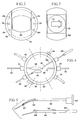
- Figure 2 illustrates an imaging plate provided with an imaging aperture.
- Figure 3 illustrates an imaging slide to be fitted in the imaging plate.
- Figure 4 illustrates the positioning of instruments within the adapter structure.
- Figure 5 illustrates shaft and instrument models which can be fitted in the adapter frame and locked in place.
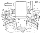
- Figure 6 is a partial sectional side view of the brain surgery adapter clamped to the skull and ready for imaging.
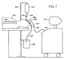
- Figure 7 illustrates the operation system during brain surgery.
- Figure 8 illustrates schematically planes within a tumor area as shown in a certain set of coordinates.
- Figure 9 illustrates schematically individual imagings performed in two different directions.
- Figure 10 illustrates one individual image in which a slice of tumor is visible.
- a scalp incision 1 is shown at the bottom in Figure 1.
- the scalp 2 is turned aside from the incision with a fold 3.
- Holes 5 are bored in the skullbone 4 for craniotomy, and the edge of the craniotomy opening 6 between the holes is sawed so as to make it slanted in order that the bone flap to be positioned in place after the operation would not press the dura 7.
- a dural incision 8 is nearly as large as the craniotomy opening, the size of which, in turn, is of the same order as the size of an operative opening 21 of a sealing plate 20.
- the cortex 10 is visible and convolutions 11 are seen on the cortex.
- the tumor to be removed is positioned somewhere within the skull, in the white matter of the brain, for instance.
- the sealing plate 20 positioned above the craniotomy opening fits tightly in a fitting groove 33 provided on the underside of an adapter frame 30.
- a skull seal 23 of suitable shape is fastened on the lower surface of the plate 20 at the edge of the operative opening 21 in such a way that it also follows the edges of the craniotomy opening 6.
- the skull seal is manufactured of suitable cellular rubber material resistant to sterilizing by casting into suitable dimensions and shape.
- the skull seal 23 is attached to the lower surface of the sealing plate 20 e.g. by means of an adhesive layer 24. If the sealing plate 20 is fastened directly to the craniotomy opening 6, this is carried out by means of screws inserted into holes 22.
- the adapter frame 30 shown in Figure 1 above the sealing plate 20 is provided with shaft holes 42 which in Figure 1 have a mutual spacing of 30 degrees and are provided with friction surfaces for friction locking by means of which the shafts are locked in place.
- the shaft holes 42 may also be provided with threadings in which case they are locked by means of locking nuts.
- a locking groove 33 (shown in Figure 6) is provided on the edge of an instrument space 31 of the adapter frame 30 for the eccentrics 86 of turn latches 83 of the imaging plate ( Figure 6).
- the locking groove 33 may also be used for the fastening of additional instruments.
- the underside of the imaging plate 70 shown above the adapter frame 30 is provided with a fitting groove for the adapter frame 30.
- the imaging plate 70 comprises a slide space 71 and an imaging aperture 80.
- the imaging plate 70 can be turned upon the adapter frame 30 without any obstacle; it can be fastened as well as locked in any desired position by means of turn latches 83 which are preferably four in number and which are mounted in turn latch holes 84.
- a slide bar 72 formed on the edge of the slide space 71 comprises a movement mechanism 73 provided with a displacing lever 74 for moving an imaging slide 90. By means of the mechanism 73, the imaging slide 90 can be moved accurately and locked in a certain position.
- the outer periphery of the imaging plate 70 is provided with a scale 81 for determining the imaging direction. Both edges of the imaging plate 70 are provided with air removal valves 77 through which air is released from the liquid space when the space is filled up.
- the imaging slide 90 shown above the imaging plate 70 in Figure 1 fits in the slide space 71 of the imaging plate 70.
- the imaging slide 90 is provided with a space 91 for the socket of the transducer and with a socket locking means 94.
- a displacing cogging 92 is formed on the edges of the imaging slide 90 for the linear movement of the imaging slide 90 between the different individual imagings.
- Cog extensions 93 function as a scale by means of which the position of the individual images is determined.
- Turning marks 96 function as indicators of the turning of the transducer.
- the imaging slide 90 can be detached entirely or turned aside during the operative procedure.
- a transducer socket 110 comprises a transducer seal 119 positioned in a transducer opening 111, the seal 119 being intended for supporting and sealing various kinds of transducers.
- a socket shoulder 112 seals the transducer socket 110 against the edge of the socket opening 91 of the imaging slide 90.
- the transducer socket 110 is provided with a socket groove 113 cut into its periphery for the turning and locking of the transducer. The transducer is locked in place by means of a transducer locking means 114.
- the vertical position of the transducer 120 in the socket 110 is adjustable so that the distance of the imaging objects from the coordinate plane can be correspondingly varied in the imaging.
- the holes 115 are provided for the mounting of additional devices and instruments.
- a hole 116 is provided for a biopsy forceps guide provided with a ball joint which can be locked. The biopsy line is thereby located in the image plane.
- a socket scale 118 is provided on the edge of the transducer socket 110, by means of which scale the turning of the transducer 120 can be observed in a set of spherical coordinates.
- the transducer 120 mounted in the transducer socket 110 is an ultrasonic linear or sector transducer.
- a cable 121 connects the transducer 120 to the imaging apparatus.
- Figure 2 shows the slide space 71 provided in the imaging plate 70, holes 78 for the air removal valves and holes 84 for the turn latches. The figure also shows the imaging aperture 80.
- Figure 3 shows the space 91 provided in the imaging slide 90 for the transducer socket 110.
- a rectangle 117 drawn in the figure illustrates the position of the transducer and the arrows illustrate the turning of the transducer with the transducer socket attached to the imaging slide.
- Figure 4 shows a few shafts and other components clamped within the adapter frame 30 at regular intervals of 30 degrees.
- a shaft 50 is provided with a flexible tissue spatula 56 and it can be entirely inserted into the shaft hole of the adapter frame 30 and locked at a suitable position after it is oriented and placed in position.
- a jointed shaft 54 is provided with a spatula 55 which can be positioned in a desired position.
- a shaft 57 provided with a skull fastening rib 58 is inserted into the shaft hole from within the adapter frame 30, and is clamped by drawing from outside the frame, whereafter it is locked in place.
- the adapter frame 30 can be secured to the operating table by means of some other supporters.
- a rigid instrument shaft 59 is provided with a handle 60 and its point 61 may be, in real-time imaging, for instance, a tissue hook, an imaging mark or some other detachable instrument.
- the locking of the shafts is carried out either with a locking nut 51 or a friction locking means 46.
- the fixing of the shafts of the brain surgery adapter may also be ridig instead of adjustable.
- the adapter frame 30 is provided with a filling connection 45 and a discharge connection 47 for the liquid.
- a closing plug 44 prevents the liquid from flowing out through empty shaft holes.
- Figure 5 shows two specific tissue supports.
- a shaft 62 is provided with a flexible part 63 and it can be locked at a desired angle by means of a locking disc 64.
- the flexible shaft portion may be provided with gripping tweezers 53 in which case the spatula is replaceable.
- a shaft 65 is provided with a joint 66.
- the joint may also be replaced with gripping means for various kinds of auxiliary devices.
- Figure 5 shows a ball joint 52 and locking means 67 for locking the joint 64.
- Figure 6 shows a brain surgery adapter 150 when it is assembled, mounted in place and ready for imaging.
- the adapter 150 is clamped to the edge of the craniotomy opening 6 by means of the skull fastening rib 58, for instance.
- the dura 7, the brain tissue 10 and the tumor 15 are shown in the figure.
- the brain tissue 10 is retracted from the tissue incision and supported by means of the spatula 56 so that the tumor 15 becomes visible.
- the scalp 2 has been removed from the area of the craniotomy opening and turned aside with a loose fold 3.
- the skull seal 23 positioned upon the skullbone 4 is attached to the sealing plate 20, which, in turn, is tightly fitted in the fitting groove 32 of the adapter frame 30.
- the adapter frame 30 comprises an unthreaded shaft hole 42 for the friction locking means 46.
- the ball joint 52 is visible within the shaft hole 42, which ball joint locks in position the shaft 50 going through the hole.
- the shaft hole 40 on the opposite side of Figure 6 is provided with a locking threading 41 into which the locking nut 51 is screwed so that the shaft 57 of the skull fastening rib will be locked in place by means of the ball joint.
- the imaging plate 70 positioned upon the adapter frame 30 is locked in place by means of the eccentrics 86 of the turn latches 83 from the locking groove 33 of the adapter frame.
- the imaging slide 90 positioned above the imaging aperture 80 of the imaging plate 70 is supported stationary by means of the slide bars 72, and it is moved by means of the displacing mechanism 73 and the displacing lever 74.
- the imaging plate 70 further comprises the air removal valve 77 and the fitting groove 85 of the adapter frame.
- the transducer socket 110 fitted in the imaging slide comprises not only the shoulder 112 but also the socket groove 113, which is used as an aid in the locking.
- the transducer seal 119 positioned in the transducer opening of the socket 110 supports the ultrasonic transducer 120, which is further locked in place by means of the transducer lock.
- An element matrix 123 of the lower portion of the ultrasonic transducer 120 is directed to the imaging object.
- the cable 121 connects the transducer 120 to the other parts of the imaging apparatus.
- the brain surgery adapter thus defines a closed liquid space 155 the upper surface of which does not need to be horizontally positioned for the imaging.
- FIG. 7 illustrates the intraoperative operation arrangement.
- the brain surgery adapter 150 is connected to the craniotomy opening of a patient 158.
- a liquid bottle 143 suspended from a supporting rack 167 is at a suitable height for creating a slight pressure in the filling hose 144, which is provided with a closing spring 145.
- the discharge hose 162 passes freely downwards into an emptying bag 166.
- the discharge hose 162 is provided with an emptying spring 164.
- the imaging plate can be turned aside or it can be placed on a platform 169 shown in the figure where it stays sterile.
- the cable 121 connects the transducer 120 to the other parts of the imaging apparatus 170, the monitor 171 of which is positioned suitably in view of the operation.
- Figure 8 illustrates schematically planes or individual images within the tumor area in a certain set of coordinates. These individual images provide a three-dimensional determination of the tumor and its location.
- the individual images are comparable with x-ray CT and NMR images, and they can be used for controlling and observing the operation.
- the individual images can be positioned in a determined set of x-y-z -coordinates or, if the imagings are carried out by turning the transducer around the central axis, the individual images are positioned within circular or spherical coordinates so that it is also possible to localize the extent of the outer dimensions of the tumor solely by means of the adapter frame.
- Figure 9 illustrates the possibility of performing imagings from different directions by turning the imaging plate. This is necessary, if an irregularly defined tumor is to be imaged during operation, for example.
- Figure 10 illustrates schematically one individual image, from which the dimensions of the tumor can be measured in a given plane.
- the craniotomy opening 6 of Figure 1 and 6 is made by known methods after the optimum resection site of the tumor has been determined by x-ray CT or other such imaging.
- the scalp incision is made slightly larger than the craniotomy so that the skull seal 23 can be positioned within the area between the edge of the scalp and that of the skullbone.
- the incised scalp is drawn aside sufficiently and fixed so that the adapter frame would not press it.
- the craniotomy opening 6 is positioned on the basis of the preoperative data in such a manner that the tumor is located in the middle of the imaging area as viewed from the operative direction so that the tissue incision can be performed within the central area in such an extent as required.
- the apparatus It is also possible to control an operation carried out in an oblique direction by means of the apparatus.
- the dural incision 8 is performed in a normal way and the dura is drawn aside and fixed.
- the adapter frame 30 is positioned upon the sealing plate 20 fitted in the craniotomy opening 6 and it is fixed either directly to the skullbone 4 by means of screws or to the edges of the craniotomy opening by means of the skull fixing ribs, the straight end portions of which are inserted through the shaft holes from within the adapter frame 30 at suitable positions to be mounted therein.
- the skull fixing ribs are locked by means of the ball joint and the locking nut by turning these into the corresponding shaft holes.
- Hoses 144 and 162 are positioned in two of the shaft holes for filling the liquid space and for discharging liquid respectively.
- the hoses are provided with plug-like clamps.
- the discharge hoses 162 and the filling hoses 144 are provided with spring compressors 145, 164 which function as taps.
- the transducer 120 is positioned in the transducer socket 110, and the transducer with the socket and the imaging slide 90 are mounted in position in the imaging plate 70 and the imaging plate is locked by means of the turn latches 83 to the adapter frame 30, the liquid space can be filled with a saline solution for the imagings.
- the discharge hose 162 is closed, one air removal valve 77 is drawn into the upper position and liquid is tapped from the suspended bottle 143 by opening the closing spring 145 until the liquid starts to flow out of the air removal valve 77, which is closed immediately.
- the liquid space 155 is kept filled with liquid.
- the brain surgery adapter 150 is now ready for imaging.
- the imaging plate 70 can be locked in a determined position and the value of the slide scale 94 is written down and the individual images can be taken by intermittently pressing the slide displacing lever 74, continually observing the slide scale 93.
- the imaging plate 70 can be locked in a determined position and the value of the slide scale 94 is written down and the individual images can be taken by intermittently pressing the slide displacing lever 74, continually observing the slide scale 93.
- the first tissue incision is made on the basis of this determination, the tumor being visible in the incision, provided that it is distinguishable from the surrounding tissue.
- Information obtained by means of ultrasound imaging can be utilized e.g. for controlling tissue destructing devices based on laser or ultrasound.
- An auxiliary device to be attached to the adapter frame may be a measuring device comprising several degrees of freedom which can be used for obtaining measuring results of various kinds from the tissue incision and also for transferring measuring results information to the tissue incision.
Landscapes
- Health & Medical Sciences (AREA)
- Life Sciences & Earth Sciences (AREA)
- Surgery (AREA)
- Heart & Thoracic Surgery (AREA)
- Molecular Biology (AREA)
- Nuclear Medicine, Radiotherapy & Molecular Imaging (AREA)
- Pathology (AREA)
- Veterinary Medicine (AREA)
- Engineering & Computer Science (AREA)
- Biomedical Technology (AREA)
- Public Health (AREA)
- Medical Informatics (AREA)
- General Health & Medical Sciences (AREA)
- Animal Behavior & Ethology (AREA)
- Biophysics (AREA)
- Physics & Mathematics (AREA)
- Radiology & Medical Imaging (AREA)
- Oral & Maxillofacial Surgery (AREA)
- Neurology (AREA)
- Ultra Sonic Daignosis Equipment (AREA)
- Magnetic Resonance Imaging Apparatus (AREA)
- Apparatus For Radiation Diagnosis (AREA)
Priority Applications (1)
| Application Number | Priority Date | Filing Date | Title |
|---|---|---|---|
| AT87900146T ATE103157T1 (de) | 1985-12-02 | 1987-06-10 | Adapter fuer gehirnchirurgie. |
Applications Claiming Priority (2)
| Application Number | Priority Date | Filing Date | Title |
|---|---|---|---|
| FI854751A FI73591C (fi) | 1985-12-02 | 1985-12-02 | Hjaernavbildningsadapter. |
| FI854751 | 1985-12-02 |
Publications (2)
| Publication Number | Publication Date |
|---|---|
| EP0409822A1 EP0409822A1 (en) | 1991-01-30 |
| EP0409822B1 true EP0409822B1 (en) | 1994-03-23 |
Family
ID=8521776
Family Applications (1)
| Application Number | Title | Priority Date | Filing Date |
|---|---|---|---|
| EP87900146A Expired - Lifetime EP0409822B1 (en) | 1985-12-02 | 1987-06-10 | An adapter for brain surgery |
Country Status (7)
| Country | Link |
|---|---|
| US (1) | US4834089A (da) |
| EP (1) | EP0409822B1 (da) |
| JP (1) | JPS63502080A (da) |
| DE (1) | DE3689744T2 (da) |
| DK (1) | DK402087D0 (da) |
| FI (1) | FI73591C (da) |
| WO (1) | WO1987003190A1 (da) |
Families Citing this family (21)
| Publication number | Priority date | Publication date | Assignee | Title |
|---|---|---|---|---|
| DE3826709C2 (de) * | 1987-08-05 | 1994-12-22 | Toshiba Kawasaki Kk | Ultraschall-Therapiegerät |
| DE4404252A1 (de) * | 1994-02-10 | 1995-08-17 | Univ Ludwigs Albert | Vorrichtung zum Absaugen von Gasen im medizinischen Bereich |
| WO1996025882A1 (en) * | 1995-02-22 | 1996-08-29 | Groenningsaeter Aage | Method for ultrasound guidance during clinical procedures |
| DE69631957T2 (de) * | 1995-04-17 | 2006-01-05 | Chernoff, W. Gregory, Indianapolis | Chirurgische Vorrichtung |
| CN1114382C (zh) * | 1998-01-02 | 2003-07-16 | 王振民 | 脑部病灶光学定位仪 |
| DE10151398B4 (de) * | 2001-10-18 | 2005-03-17 | Schaerer Mayfield USA, Inc., Cincinnati | Vorrichtung zur Adaption chirurgischer Instrumente als Zeigereinrichtung |
| US6616604B1 (en) | 2002-04-05 | 2003-09-09 | Allegiance Corporation | Surgical retractor securing apparatus |
| US8428690B2 (en) * | 2007-05-16 | 2013-04-23 | General Electric Company | Intracardiac echocardiography image reconstruction in combination with position tracking system |
| US8989842B2 (en) * | 2007-05-16 | 2015-03-24 | General Electric Company | System and method to register a tracking system with intracardiac echocardiography (ICE) imaging system |
| US8527032B2 (en) * | 2007-05-16 | 2013-09-03 | General Electric Company | Imaging system and method of delivery of an instrument to an imaged subject |
| US8364242B2 (en) * | 2007-05-17 | 2013-01-29 | General Electric Company | System and method of combining ultrasound image acquisition with fluoroscopic image acquisition |
| US20150144144A1 (en) * | 2015-01-26 | 2015-05-28 | Michael Lewis Moravitz | Brain surgery through eye |
| EP3307175B1 (en) * | 2015-06-10 | 2025-03-19 | Institut National de la Santé et de la Recherche Médicale (INSERM) | Detecting apparatus and associated kit and method |
| JP7015694B2 (ja) * | 2015-06-16 | 2022-02-03 | アンスティチュ ナショナル ドゥ ラ サンテ エ ドゥ ラ ルシェルシュ メディカル | 検出装置および検出装置の作動方法 |
| NL1041488B1 (en) * | 2015-09-24 | 2017-04-19 | Medacc | Device for fixating a medical instrument. |
| US10912648B2 (en) * | 2016-08-30 | 2021-02-09 | Longeviti Neuro Solutions Llc | Method for manufacturing a low-profile intercranial device and the low-profile intercranial device manufactured thereby |
| DE102016116677B3 (de) * | 2016-09-06 | 2017-12-14 | Universität Duisburg-Essen | Chirurgisches Simulationsgerät |
| US9707049B1 (en) * | 2016-12-22 | 2017-07-18 | The Florida International University Board Of Trustees | Stereotactic device for implantation of permanent implants into a rodent brain |
| US10251722B1 (en) | 2018-09-17 | 2019-04-09 | The Florida International University Board Of Trustees | Stereotaxic brain implant system for large animals |
| US10918371B2 (en) * | 2019-04-03 | 2021-02-16 | Brain Innovations Llc | Apparatus and method for retracting brain tissue during brain surgery |
| CN112773455A (zh) * | 2021-01-11 | 2021-05-11 | 重庆懿熙品牌策划有限公司 | 一种锯片式开颅手术装置 |
Family Cites Families (21)
| Publication number | Priority date | Publication date | Assignee | Title |
|---|---|---|---|---|
| US1398842A (en) * | 1920-02-09 | 1921-11-29 | George M Cruse | Skullcap frame and guide |
| US2480737A (en) * | 1948-03-08 | 1949-08-30 | Jayle Gaetan Jean-Edward | Cutting instrument particularly useful in connection with corneal grafting |
| US3053256A (en) * | 1956-04-03 | 1962-09-11 | Home For Incurables | Pallidectomy needle holders |
| US3016899A (en) * | 1958-11-03 | 1962-01-16 | Carl B Stenvall | Surgical instrument |
| US3021842A (en) * | 1958-11-05 | 1962-02-20 | John F Flood | Hypodermic needle guide |
| US3115140A (en) * | 1960-08-18 | 1963-12-24 | Baltimore Instr Company | Apparatus for stereotaxic brain operations |
| US3135263A (en) * | 1960-10-05 | 1964-06-02 | Smiths America Corp | Surgical instrument positioning device |
| FR1311384A (fr) * | 1961-10-27 | 1962-12-07 | Alexandre & Cie | Appareil permettant l'exploration complète du cerveau en neurochirurgie stéréotaxique |
| US3263683A (en) * | 1963-03-14 | 1966-08-02 | Uddenberg Goran | Removal instruments for cysts located in cavities of the human body |
| US3384086A (en) * | 1966-01-10 | 1968-05-21 | Health Education Welfare Usa | Stereotaxic oriented macrotome device |
| US3817249A (en) * | 1972-04-07 | 1974-06-18 | Neuro Probe Inc | Stereotaxic instrument |
| DE2443558B2 (de) * | 1974-09-11 | 1979-01-04 | Siemens Ag, 1000 Berlin Und 8000 Muenchen | Vorrichtung zum Punktieren von körperinternen Organen und Gefäßen |
| US4206763A (en) * | 1978-08-01 | 1980-06-10 | Drexel University | Ultrasonic scanner for breast cancer examination |
| US4608977A (en) * | 1979-08-29 | 1986-09-02 | Brown Russell A | System using computed tomography as for selective body treatment |
| DE2948986C2 (de) * | 1979-12-05 | 1982-10-28 | Siemens AG, 1000 Berlin und 8000 München | Medizinische Untersuchungsanlage |
| US4485819A (en) * | 1980-01-21 | 1984-12-04 | Wolfgang Igl | Mechanical accessory for commercially available compound apparatuses for echo mammography |
| US4638798A (en) * | 1980-09-10 | 1987-01-27 | Shelden C Hunter | Stereotactic method and apparatus for locating and treating or removing lesions |
| US4688570A (en) * | 1981-03-09 | 1987-08-25 | The Regents Of The University Of California | Ophthalmologic surgical instrument |
| JPS582249U (ja) * | 1981-06-29 | 1983-01-08 | 松下電工株式会社 | 床板 |
| DE3244667C2 (de) * | 1982-12-02 | 1987-01-22 | Siemens AG, 1000 Berlin und 8000 München | Ultraschall-Applikator für die Biopsie |
| JPS60217073A (ja) * | 1984-04-13 | 1985-10-30 | 三菱重工業株式会社 | 多本指マニプレ−タ |
-
1985
- 1985-12-02 FI FI854751A patent/FI73591C/fi not_active IP Right Cessation
-
1986
- 1986-12-01 DE DE3689744T patent/DE3689744T2/de not_active Expired - Fee Related
- 1986-12-01 WO PCT/FI1986/000139 patent/WO1987003190A1/en not_active Ceased
- 1986-12-01 US US07/086,691 patent/US4834089A/en not_active Expired - Fee Related
- 1986-12-01 JP JP62500041A patent/JPS63502080A/ja active Pending
-
1987
- 1987-06-10 EP EP87900146A patent/EP0409822B1/en not_active Expired - Lifetime
- 1987-07-31 DK DK402087A patent/DK402087D0/da not_active Application Discontinuation
Also Published As
| Publication number | Publication date |
|---|---|
| FI854751A7 (fi) | 1987-06-03 |
| DK402087A (da) | 1987-07-31 |
| DK402087D0 (da) | 1987-07-31 |
| DE3689744D1 (de) | 1994-04-28 |
| FI854751A0 (fi) | 1985-12-02 |
| DE3689744T2 (de) | 1994-06-30 |
| US4834089A (en) | 1989-05-30 |
| JPS63502080A (ja) | 1988-08-18 |
| FI73591B (fi) | 1987-07-31 |
| FI73591C (fi) | 1987-11-09 |
| WO1987003190A1 (en) | 1987-06-04 |
| EP0409822A1 (en) | 1991-01-30 |
Similar Documents
| Publication | Publication Date | Title |
|---|---|---|
| EP0409822B1 (en) | An adapter for brain surgery | |
| Kato et al. | A frameless, armless navigational system for computer-assisted neurosurgery | |
| US20040243146A1 (en) | Method and apparatus for supporting a medical device | |
| US5943719A (en) | Method and device for precise invasive procedures | |
| US6206890B1 (en) | Remote actuation of trajectory guide | |
| US4681103A (en) | Ultrasound guided surgical instrument guide and method | |
| US4955891A (en) | Method and apparatus for performing stereotactic surgery | |
| Kelly et al. | The stereotaxic retractor in computer-assisted stereotaxic microsurgery | |
| DE69832425T2 (de) | System zur Durchführung von Chirurgie, Biopsie, Ablation eines Tumors oder einer anderen physikalischen Anomalie | |
| US4733661A (en) | Guidance device for C.T. guided drainage and biopsy procedures | |
| US6752812B1 (en) | Remote actuation of trajectory guide | |
| Nauta | Error assessment during “image guided” and “imaging interactive” stereotactic surgery | |
| EP1958588A2 (en) | Medical guide for guiding a medical instrument | |
| US20130133670A1 (en) | Surgical drape | |
| US10842527B2 (en) | Systems and methods for preparing tissue flaps | |
| Moissonnier et al. | Accuracy testing of a new stereotactic CT-guided brain biopsy device in the dog | |
| Sutcliffe | The value of intraoperative ultrasound in neurosurgery | |
| US20110201965A1 (en) | MRI Compatible Biopsy Device | |
| Klimek et al. | Computer-assisted image-guided surgery in pediatric skull-base procedures | |
| Giorgi et al. | Preliminary clinical experience with intraoperative stereotactic ultrasound imaging. | |
| Giorgi et al. | A computer controlled stereotactic arm: virtual reality in neurosurgical procedures | |
| Lee et al. | Intraoperative ultrasound in intracranial surgery | |
| Hassfeld et al. | Possibilities and developments of intraoperative image-guided surgery in craniofacial surgery | |
| Brommeland et al. | Mechanical accuracy of a new stereotactic guide | |
| Unsgård et al. | Intraoperative ultrasound in neurosurgery |
Legal Events
| Date | Code | Title | Description |
|---|---|---|---|
| PUAI | Public reference made under article 153(3) epc to a published international application that has entered the european phase |
Free format text: ORIGINAL CODE: 0009012 |
|
| 17P | Request for examination filed |
Effective date: 19880601 |
|
| AK | Designated contracting states |
Kind code of ref document: A1 Designated state(s): AT BE CH DE FR GB IT LI LU NL SE |
|
| 17Q | First examination report despatched |
Effective date: 19921102 |
|
| GRAA | (expected) grant |
Free format text: ORIGINAL CODE: 0009210 |
|
| AK | Designated contracting states |
Kind code of ref document: B1 Designated state(s): AT BE CH DE FR GB IT LI LU NL SE |
|
| PG25 | Lapsed in a contracting state [announced via postgrant information from national office to epo] |
Ref country code: IT Free format text: LAPSE BECAUSE OF FAILURE TO SUBMIT A TRANSLATION OF THE DESCRIPTION OR TO PAY THE FEE WITHIN THE PRESCRIBED TIME-LIMIT;WARNING: LAPSES OF ITALIAN PATENTS WITH EFFECTIVE DATE BEFORE 2007 MAY HAVE OCCURRED AT ANY TIME BEFORE 2007. THE CORRECT EFFECTIVE DATE MAY BE DIFFERENT FROM THE ONE RECORDED. Effective date: 19940323 Ref country code: AT Effective date: 19940323 Ref country code: NL Effective date: 19940323 Ref country code: LI Effective date: 19940323 Ref country code: FR Effective date: 19940323 Ref country code: SE Free format text: THE PATENT HAS BEEN ANNULLED BY A DECISION OF A NATIONAL AUTHORITY Effective date: 19940323 Ref country code: CH Effective date: 19940323 Ref country code: BE Effective date: 19940323 |
|
| REF | Corresponds to: |
Ref document number: 103157 Country of ref document: AT Date of ref document: 19940415 Kind code of ref document: T |
|
| REF | Corresponds to: |
Ref document number: 3689744 Country of ref document: DE Date of ref document: 19940428 |
|
| REG | Reference to a national code |
Ref country code: CH Ref legal event code: PL |
|
| EN | Fr: translation not filed | ||
| NLV1 | Nl: lapsed or annulled due to failure to fulfill the requirements of art. 29p and 29m of the patents act | ||
| PG25 | Lapsed in a contracting state [announced via postgrant information from national office to epo] |
Ref country code: GB Effective date: 19941201 |
|
| PG25 | Lapsed in a contracting state [announced via postgrant information from national office to epo] |
Ref country code: LU Free format text: LAPSE BECAUSE OF NON-PAYMENT OF DUE FEES Effective date: 19941231 |
|
| PLBE | No opposition filed within time limit |
Free format text: ORIGINAL CODE: 0009261 |
|
| 26N | No opposition filed | ||
| PGFP | Annual fee paid to national office [announced via postgrant information from national office to epo] |
Ref country code: DE Payment date: 19950629 Year of fee payment: 9 |
|
| GBPC | Gb: european patent ceased through non-payment of renewal fee |
Effective date: 19941201 |
|
| PG25 | Lapsed in a contracting state [announced via postgrant information from national office to epo] |
Ref country code: DE Effective date: 19960903 |