EP0409262A2 - Aufzeichnungsgerät und -verfahren mittels Thermoübertragung - Google Patents
Aufzeichnungsgerät und -verfahren mittels Thermoübertragung Download PDFInfo
- Publication number
- EP0409262A2 EP0409262A2 EP90113954A EP90113954A EP0409262A2 EP 0409262 A2 EP0409262 A2 EP 0409262A2 EP 90113954 A EP90113954 A EP 90113954A EP 90113954 A EP90113954 A EP 90113954A EP 0409262 A2 EP0409262 A2 EP 0409262A2
- Authority
- EP
- European Patent Office
- Prior art keywords
- recording
- ink sheet
- conveying
- recording medium
- sheet
- Prior art date
- Legal status (The legal status is an assumption and is not a legal conclusion. Google has not performed a legal analysis and makes no representation as to the accuracy of the status listed.)
- Granted
Links
Images






Classifications
-
- B—PERFORMING OPERATIONS; TRANSPORTING
- B41—PRINTING; LINING MACHINES; TYPEWRITERS; STAMPS
- B41J—TYPEWRITERS; SELECTIVE PRINTING MECHANISMS, i.e. MECHANISMS PRINTING OTHERWISE THAN FROM A FORME; CORRECTION OF TYPOGRAPHICAL ERRORS
- B41J17/00—Mechanisms for manipulating page-width impression-transfer material, e.g. carbon paper
- B41J17/02—Feeding mechanisms
- B41J17/12—Special adaptations for ensuring maximum life
Definitions
- the present invention relates to an apparatus and a method of thermal transfer recording to record image on a recording medium by transferring ink of the ink sheet on the recording medium.
- a thermal transfer printer records the image by using an ink sheet obtained by coating heat-meltably (or heat-sublimable, etc.) ink on a base film, heating such ink sheet by the thermal head selectively responding to the image signal and transferring the molten (or sublimated, etc.) ink on to the recording sheet. Since this ink sheet is generally of such type that by one image recording, the ink is completely transferred to the recording sheet (the so-called one-time ink sheet), it was necessary that when recording of one character or one line is over, the ink sheet should be conveyed for the length corresponding to the recorded length so that an unused part of the ink sheet comes to the succeeding recording position with certainty. As the result, the amount of use of the ink sheet increases, and the running cost of thermal transfer printer tends to become high.
- An objective of the present invention is to provide a thermal transfer recording apparatus and a method which enable to make a clear record.
- Another objective of the present invention is to provide a thermal transfer recording apparatus and the method which enable to convey the ink sheet in preferred state.
- Still another objective of the present invention is to provide a thermal transfer and recording apparatus and the method which enable to prevent wrinkling or slackening of ink sheet.
- Still another objective of the present invention is to provide, in the light of the conventional examples, the thermal transfer and recoridng apparatus wherein sagging etc of ink sheet is prevented by conveying ink sheet and the recording sheet in the same direction when recording medium returns in the direction opposite to the recording direction and friction force between ink sheet and recording medium becomes larger than the predetermined level.
- Figs. 1 - 4 are drawings to show the facsimile equipment used as the thermal printer of the embodiment of the present invention.
- Fig. 1 is the drawing to show the electric connection between the control unit and the recording unit;
- Fig. 2 is the block diagram to show the outline of the composition of the facsimile equipment;
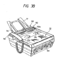
- Fig. 3A is the drawing of the side section of the facsimile equipment and
- Fig. 3B is the perspective view of its appaearance.
- While 111 is an encoding/decoding unit to encode the received image information by MH encoding and decode the encoded image data received and convert it into image data.
- 112 is a buffer memory to store the encoded image data received or to be transmitted.
- Each of these sections of the control unit 101 is controlled for example by the CPU 113 of the micro-processor.
- the control unit 101 is provided with, in addition to CPU 113, the control program of CPU 113 and ROM 114 which memorize various data, RAM 115 which temporarily stores various data operating as the work area of CPU 113.
- the recording unit 102 is the recording unit to execute recording of image on the recording sheet by thermal transfer recording method which is provided with the thermal line head having a plurality of heat generating devices 132 to cover the entire recording width.
- 10 is the rolled sheet which rolls up the recording sheet 11, which is the ordinary sheet, on the core 10a.
- This rolled sheet 10 is rotatably housed in the unit so that the recording sheet 11 can be delivered to the recording position where thermal head 113 exists as the platen roller 12 rotates in the direction of arrow.
- 10b is the unit at which rolled sheet is set, rolled sheet 10 being set in the way that it can be mounted or dismounted as desired.
- 12 is the platen roller which conveys the recording sheet 11 in the direction of arrow b . This platen roller 12 presses the ink sheet 14 and recording sheet 11 against the heat generating member 132 of thermal head 13.
- Figs. 4A and 4B are the drawings to show the details of conveying mechanism of recording sheet 11. The same parts given in the prior drawing are given the same number and their explanations are omitted here.
- This torque limiter 85 is provided at the edge of the shaft 86a of the aforesaid transmission gear 86.
- the torque limiter 85 is so set that it applies the load of about 1.6 kg.cm on the axis 17a of ink sheet feed roll 17.
- the diameter of the ink sheet roll 17 changes, as the ink sheet 14 is fed, from about 44 mm (at the beginning of use) to about 19 mm (at the end of use -- it is equivalent to the diameter of the core 17b) and therefore the tension applied to the ink sheet 14 gradually changes from about 0.36 kg to about 0.84 kg.
- V PI V P -n ⁇ V I (V I is the conveying speed of ink sheet 14 and - indicates that the conveying direction of recording sheet 11 differs from the conveying direction of ink sheet 14)
- ink sheet 14 is conveyed in the direction of arrow a by (l/m) (m is integral number and n > m) for each (n/m) line when recording is made for n line by thermal head 13.
- ink sheet 14 is conveyed at the same speed but in the reverse direction to the direction of motion of recording sheet 11 and prior to succeeding recording of the preset amount, the ink sheet 14 is rewinded for L ⁇ (n - l)/n (here n > l).
- the relative speed at which recording is made while keeping the ink sheet 14 standstill is V P and the relative speed of recording while the ink sheet 14 is in motion is 2V P .
- Fig. 4B is the device wherein manual cutter 15C is provided at the down stream side of the discharge roller 16 is instead of cutter 15. Even when the device has such construction that manual cutter 15C is provided, the similar effect may be obtained by exercising conveying control as long as it is assumed that there is no back feed procedure as stated later.
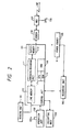
- Fig. 1 shows the connection of electric system of control unit 101 and recording unit 102 of the facsimile of the present example of embodiment wherein the parts common with those of other drawings are given the same number.
- the kind (characteristics) of the ink sheet 14 is instructed by the switch 103a. It may alternatively so arranged that the kind and characteristics of ink sheet 14 is automatically detected by the mark etc printed on the ink sheet 14. Or, alternatively it may be so arranged that judgement is made based on the mark given to the cartridge of the ink sheet or the notch or projections provided to the cartridge.
- the driving circuit 46 is the driving circuit to output the strobe signal 47 which inputs the driving signal of thermal head from the aforesaid control unit 101 and drives the thermal head 13 block by block.
- This driving circuit 46 can change the voltage output to the power source cable 45 which feeds current to the heat generating apparatus 132 of the thermal head 13 according to the instruction of the control unit 101 and thereby change the energy impressed on thermal head 13.
- 48 and 49 are motor driving circuits which respectively drive and rotate the motor 24 for conveying recording sheet and motor 25 for conveying ink sheet.
- the motor 24 used for conveying the recording sheet and the motor 25 for conveying ink sheet are stepping motor but they are not limited thereto and they may be for example DC motor.
- Fig. 6 shows the state where image recording for one page is completed.
- the rear edge of one page where image was recorded is brought in contact with thermal head 13. Therefore in order to cut the sheet for one page length by the cutter 15, it is necessary to convey the recording sheet 11 further forward (direction or arrow b ) by the length "l" which is the distance between the recording position of thermal head 13 and cutter 15.
- Fig. 7A is the drawing to show the state at the time of such conveying wherein the conveying speed of recording sheet 11 is assumed to be V PF (in the present embodiment, V PF ⁇ 52[mm/S]).
- V PF in the present embodiment, V PF ⁇ 52[mm/S]
- ink sheet conveying motor is stopped by fixing the phase excitation signal of ink sheet conveying motor 25 by the driving circuit 49. Thereby holding torque is produced at motor 25 and wind-up roll 18 is restricted of its rotation.
- the motor for driving the cutter 15 drives by the instruction of control unit 101 and moving blade 15a and fixed blade 15b gear with each other and recording sheet is cut for one page length.
- 11a is one page length of recording sheet duly recorded; 11b is the rear edge of one page of recording sheet 11a which has been cut and 11c is the front edge of one page of recording sheet 11a having been cut.
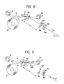
- Fig. 9 is the drawing to show the state wherein the recording sheet 11 is rewinded in the direction opposite to the direction of arrow b of Fig. 7A, after cutting of recording sheet 11, conveying it to the position where the front edge of the recording sheet 11 projects somewhat from the transfer position of thermal head to the side of sheet discharge roller 16 and thus projecting the sheet front for recording of the succeeding page.
- the speed of rewinding of recording sheet 11 at such time is assumed to be V PB (in the present embodiment, V PB ⁇ -52[mm/S].
- ink sheet 14 is pulled by the recording sheet 11 in the direction opposite to the direction of arrow b .
- the rotary axis 17a of ink sheet feed roll 17 bears the load of torque limiter 85. Therefore, when the force to pull ink sheet 14 in the direction of arrow a becomes larger than the load of torque limiter 85, the ink sheet 14 is moved backward (direction of arrow a ) at the speed slower than the speed V PB of recording sheet 11. The amount of such shift offsets the difference between the conveying force given by the friction between the ink sheet 14 and recording sheet 11 and the holding force given by the load of torque limiter 85. Simultaneously, the recording sheet 11a which was recorded and cut is discharged to outside the apparatus by the rotation of discharge roller 16.
- the ink sheet 14 In the standby state before image recording (shown in Figure 5), the ink sheet 14 must be spread without sagging between the ink sheet wind-up roll 18 and thermal head 13. It is because, at the start of image recording when ink sheet wind-up roll 18 is driven for rotation and conveying of ink sheet 14 starts, if ink sheet is sagging, the rotation of wind-up roll 18 only absorbs the sag of ink sheet 14. If so, when the image recording starts, the speed of conveying of ink sheet 14 is not equal to V1. Besides, the ink sheet 14 is drawn by the conveying of the recording sheet 11 at the speed V P and sometimes it is carried to the downstream side.
- the aforesaid offsetting amount of ink sheet 14 becomes the sag between the ink sheet wind-up roller 18 and platen roll 12. Therefore before the succeeding recording starts, this sag must be eliminated so that the sheet is spread with appropriate tension.
- ink sheet 14 is completely strained by conveying it in the same direction (direction of arrow a ) after completion of rewinding of recording sheet.
- the ink sheet 14 is conveyed in the direction of arrow a at speed V IF by the rotation of the ink sheet conveying motor 25 as shown Fig. 7B.
- ink sheet 14 is moved in the direction of arrow a at the speed slower than the recording sheet 11 due to the load of to torque limiter 85 and the friction of recording sheet 11 and ink sheet 14 as stated above.
- n IF > n (n is equal to n during recording).
- the third embodiment is the case where, in the aforesaid first and second embodiment before starting recording, ink sheet 14 is further winded up to eliminate the sag of the ink sheet 14.
- the ink sheet conveying motor 25 is driven for rotation and ink sheet 14 is conveyed in the direction of arrow a for wind-up and it is checked if ink sheet feed roll 17 is rotating or not by the ink sensor 19. If rotation is not detected, the ink sheet conveying motor 25 is further caused to rotate. When the rotation of feed roll 17 is detected by ink sheet sensor 19, it is so judged that ink sheet 14 has been spread without sagging. According to this embodiment, in the standby state, ink sheet 14 is spread without sagging between the ink sheet wind-up roll 18 and thermal head 13.
- step S1 recording data for one line are output in series on to the shift register 130.
- latch signal 44 is output at step S2 and recording data for one line is housed in the latch circuit 131.
- step S3 ink sheet conveying motor 25 and ink sheet feeding motor 85 are driven to convey ink sheet 14 for (l/n) line to the direction of arrow a in Fig. 3.
- step 4 the recording sheet conveying motor 24 is driven to convey the recording sheet 11 for one line to the direction of arrow b.
- the length of one line corresponds to the length of 1 dot to be recorded by the thermal head 13.
- step S5 each block of heat generating apparatus 132 of thermal head is electrified one after another.
- step S6 image recording for one line has been completed or not.
- step S7 the recorded data of the following line are transferred to the shift register 130 of thermal head 13. Then the mode returns to step S2 and image recording is conducted as aforesaid.
- step S6 if image recording for one page is completed, the mode proceeds to step S8 and the recording sheet 11 is conveyed to the direction of discharge rollers 16a and 16b for the distance corresponding to the length l which is roughly the distance between the recording position of thermal head 13 and the cutter 15.
- phase excitation signal of ink sheet conveying motor 25 is fixed by driving circuit 49 and ink sheet conveying motor 25 is stopped. In this way, the ink sheet 14 is held in the strained state in between the ink sheet feed roll 17 and ink sheet wind-up roll 18.
- step S9 the mobile blade 15a is driven to gear with the fixed blade 15b and cuts the recording sheet 11 for page lengths.
- the recording sheet 11 is fed back somewhat to have the edge of the sheet projects at the recording position.
- ink sheet 14 moves backward at the speed slower than that of recording sheet 11 to the extent in excess of the load of torque limiter 85, due to the friction of ink sheet 14 and the recording sheet 11.
- step S11 ink sheet conveying motor 25 is caused to rotate for the specified amount and ink sheet 14 is conveyed backward to absorb the sag and at step S12, the recorded sheet 11a is discharged to outside the apparatus by discharge roller 16.
- Fig. 12 is the flow chart to show the performance of the aforesaid second embodiment. It is realized by replacing the steps S8 - S10 shown in Fig. 11 by the flow chart shown in Fig. 12.
- step S31 conveying of recording sheet 11 (in the direction of arrow b) is started and at step S32, the ink sheet 14 is conveyed in the direction of arrow a at speed V IF and it is strained by the load of torque limiter 85.
- n IF is the figure larger than n mentioned above and it represents the number of sheets that can be conveyed without causing rubbing off of topcoat of ink sheet 14 by its abrasion with recording sheet 11.
- step S34 When the recording sheet 11 is cut by the cutter 15 at step S9, the mode proceeds to step S34 and recording sheet 11 returns by present amount to the direction of thermal head and the mode proceeds to step S11.
- ink sheet 14 is pulled in the direction of arrow a due to its abrasion with recording sheet 11 and by the action with the load of torque limiter 85, the ink sheet 14 is spread with strain in between the ink sheet feed roll 17 and platen roller 12.
- the control of the value of the aforesaid n may be made by changing the step number of ink sheet 14 for conveying of one line of recording sheet 11 and the value n may be set by changing the minimum step angle of the motor by microstep driving.
- step S12 ink sheet 14 sags in between the ink sheet wind-up roll 18 and platen roller 12, it may be so arranged that at the image recording of the following page, the step may be repeated from step S1 again.
- Fig. 13 is flow chart to show the performance of the aforesaid third embodiment.
- the step S01 are executed before step S1 shown in Fig. 11, while the process after step S1 is same as those of Figs. 11 and Fig. 12, thus their explanation is omitted.
- step S01 ink sheet-conveying motor 25 is driven for rotation and ink sheet 14 is conveyed in the direction of arrow a and winded up.
- step S02 the ink sheet sensor 19 checks if ink sheet feed roll 17 is rotating or not. When rotation is not confirmed, the mode returns to step S01 and ink sheet conveying motor 25 is further rotated. When rotation of feed roll 17 is detected by ink sheet sensor 19, it is so judged that the ink sheet 14 has been spread without sagging and the mode proceeds to step S1. Thereafter the performance is same as those of step S2 - step S34 (Fig. 11 and Fig. 12) stated above.
- Fig. 14 is the flow chart to show the performance of the aforesaid fourth embodiment, which is realized by replacing the step S8 - step S11 shown in Fig. 11 by the flow chart shown in Fig. 14.
- step S31 conveying of recording sheet 11 (in the direction of arrow b) starts and at step S35, the ink sheet 14 is conveyed in the direction of arrow a at speed V PF /n and by the load of torque limiter 85, ink sheet 14 is spread with strain.
- n equals to n during recording.
- n 5 but as shown in Fig. 4A, it is natural that the value of n change according to the change of outer diameter of ink sheet wind-up roll and thus the speeds of recording sheet and ink sheet naturally change. Therefore the value of the speed may be other than those mentioned in this explanation.
- the value n which determines the feed of ink sheet 14 may be changed not only by changing the rotation amount of recording sheet conveying motor 24 and ink sheet conveying motor 25 but also by changing the speed reduction radio of transmission gears 26, 27 of the driving system of platen roller 12 and the transmission gears 28, 29 of the driving system of wind-up roller 18.
- the value n may be set by selecting the different minimum step angle for the two motors. In this way, the relative speed of recording sheet 11 and ink sheet 14 may be set at (l + l/n) Vp.
- step S3 and step S3 and step S4 it is preferred to start driving of ink sheet conveying motor for conveying action earlier than the start of driving of recording sheet conveying motor 24. It is because even when the ink sheet conveying motor 25 is driven, there is a time lag until the conveying of ink sheet 14 actually starts due to the characteristics of the motor or the characteristics of the drive transmission system.
- Fig. 10 shows the state of image recording when the conveying direction of recording sheet 11 and ink sheet 14 are reversed in this embodiment.
- ink sheet 14 sandwiched between the platen roller 12 and thermal head 13 and thermal head 13 is pressed against the platen roller 12 at the specified pressure by the spring 21.
- the recording sheet 11 conveyed in the direction of arrow b by the rotation of platen roller 12 at the speed Vp.
- ink sheet 14 is conveyed in the direction of arrow a by the rotation of ink sheet conveying motor 25 at the speed V I .
- the part indicated by diagonal line 81 of ink sheet 14 is heated.
- 14a represents the base film of ink sheet 14
- 14b is the ink layer of ink sheet 14.
- the ink of the ink layer 81 melts by heating due to heating of heat generating resistor 132 as the result of electrification and the part indicated by 82 in transferred to recording sheet 11.
- Such part 82 of the ink layer roughly corresponds to l/n of the ink layer.
- shearing force is produced against the ink at the border 83 of the ink layer 14b and thereby only the part of the ink layer indicated by 82 is transferred on to the recording sheet 11.
- shearing force varies according to the temperature of ink layer and it tends to be smaller as the temperature of ink layer becomes higher.
- shearing force within the ink layer becomes larger and therefore when the relative speed of ink sheet 14 over the recording sheet 11 is larger, it is possible to peel off the ink layer from the ink sheet 14 with the higher certainly.
- heating time of thermal head of facsimile equipment is short being about 0.6 ms
- the relative speed of ink sheet 14 and recording sheet 11 may be increased.
- Fig. 15 is the sectional view of ink sheet 14 used for multi-print. Here the explanation shall be made on the ink sheet made of four layers.
- the second layer is the base film which constitutes the support of the ink sheet 14.
- the thickness of the film is preferred to be thin because of the role played by the film, that is, to be the medium to produce the print of the better quality but because of the requirement of strength, the thickness of 3 - 8 ⁇ m is preferred.
- the third layer is an ink layer where the ink for the amount sufficient for n times of transfer recording is coated.
- the ink is mainly composed of such components as EVA or other resins used for adhesive, carbon black for coloring, nigrosine dye, carnauva wax or paraffin wax for binding material, etc. so that the same spot may be used repeatedly for n times.
- Amount of coating is preferably 4 - 8 g/m2 but it may be chosen according to the need as the response and darkness of print vary according to the amount of coating.
- the fourth layer is the part not printed. It is the top coat layer which is provided to prevent the ink of the third layer transfers to the recording sheet by pressure and it is composed of transparent wax, etc. Consequently the layer which is transferred by pressure is only the transparent fourth layer and thus staining of the ground of recording sheet may be prevented.
- the first layer is a heat-resistant coating layer which protects the second layer i.e., the base film from the heat of thermal head 13. This is advantageous in the case of multi-print system wherein thermal energy for n lines may be applied on the same spot (when black information continues) but whether to use it or not may be chosen according to the need. It is effective in the case of base film of relatively low heat resistance such as polyester film.
- the base film may be the film made of polyamide, triacetyl cellulose, nylon, polyvinyl chloride or polypropylene etc. or paper.
- Heat resistant coating which is not necessarily required may be made of silicone resin, epoxy resin, melamine resin, etc.
- the ink coated on the ink sheet 14 is not limited to the hot-melt ink but hot-sublimating ink will also do.
- the ink sheet coated with such hot-sublimation ink may be so constructed that a coloring material containing spacer granules made of guanamine resin and fluororesin and dyestuff is provided on the substrate film made of, for example, polyethylene telephthalate, polystylene naphthalate or aromatic polyamide.
- the recording medium is not limited to the recording sheet but those made of the material which enables transfer of ink, for example, cloth, plastic sheet etc. will also do.
- the method of setting of ink sheet is not limited to the method to use roll shown in the embodiment but it may be for example an ink sheet cassette wherein the ink sheet is housed in a box which may be mounted on and off the main body of the recording equipment and the box as a whole is mounted on and off the main body of the recording equipment.
- thermal transfer recording apparatus is facsimile
- thermal transfer recording apparatus of the present invention is not limited thereto but it may of course be the systems such as, for example, word processor, typewriter or copying machine.
- the back feed of recording sheet 11 is exercised when the sheet is cut by the cutter 15 but it is not limited to such case but it may be exercised in the cases, for example, where recording sheet 11 is exchanged, the front end of the recording sheet 11 is conveyed to the cutter position or the front end of the recording sheet 11 is back fed to the image recording position of thermal head 13.
- such effect is obtained that staining of the surface of recording sheet or creasing or sagging of the ink sheet are prevented by stopping the conveyance of recording sheet or by conveying it at the speed slower than the conveying speed of recording sheet by straining the ink sheet at the time of front feed, while at the time of back feed of recording sheet, by conveying the ink sheet at the speed slower than the conveying speed of the recording sheet.
Landscapes
- Impression-Transfer Materials And Handling Thereof (AREA)
- Electronic Switches (AREA)
Applications Claiming Priority (4)
| Application Number | Priority Date | Filing Date | Title |
|---|---|---|---|
| JP18610989 | 1989-07-20 | ||
| JP186109/89 | 1989-07-20 | ||
| JP177364/90 | 1990-07-06 | ||
| JP2177364A JPH03130179A (ja) | 1989-07-20 | 1990-07-06 | 熱転写記録装置及び熱転写記録方法 |
Publications (3)
| Publication Number | Publication Date |
|---|---|
| EP0409262A2 true EP0409262A2 (de) | 1991-01-23 |
| EP0409262A3 EP0409262A3 (en) | 1991-05-22 |
| EP0409262B1 EP0409262B1 (de) | 1996-04-03 |
Family
ID=26497927
Family Applications (1)
| Application Number | Title | Priority Date | Filing Date |
|---|---|---|---|
| EP90113954A Expired - Lifetime EP0409262B1 (de) | 1989-07-20 | 1990-07-20 | Aufzeichnungsgerät und -verfahren mittels Thermoübertragung |
Country Status (2)
| Country | Link |
|---|---|
| EP (1) | EP0409262B1 (de) |
| DE (1) | DE69026316T2 (de) |
Family Cites Families (5)
| Publication number | Priority date | Publication date | Assignee | Title |
|---|---|---|---|---|
| US3090299A (en) * | 1961-06-02 | 1963-05-21 | Potter Instrument Co Inc | Ribbon tensioning mechanism for high speed printers |
| US4408908A (en) * | 1980-12-19 | 1983-10-11 | International Business Machines Corporation | Ribbon feed system for a matrix printer |
| GB2169875B (en) * | 1985-01-19 | 1988-09-14 | Francotyp Postalia Gmbh | Improvements in ribbon cassettes |
| EP0320284B1 (de) * | 1987-12-09 | 1993-09-01 | Shinko Electric Co. Ltd. | Nach dem Übertragungsprinzip arbeitender Thermo-Farbdrucker |
| JPH02121866A (ja) * | 1988-11-01 | 1990-05-09 | Canon Inc | 熱転写記録装置及び該装置を用いたフアクシミリ装置 |
-
1990
- 1990-07-20 EP EP90113954A patent/EP0409262B1/de not_active Expired - Lifetime
- 1990-07-20 DE DE1990626316 patent/DE69026316T2/de not_active Expired - Fee Related
Also Published As
| Publication number | Publication date |
|---|---|
| EP0409262B1 (de) | 1996-04-03 |
| DE69026316T2 (de) | 1996-09-19 |
| EP0409262A3 (en) | 1991-05-22 |
| DE69026316D1 (de) | 1996-05-09 |
Similar Documents
| Publication | Publication Date | Title |
|---|---|---|
| US5122882A (en) | Thermal transfer recording method and apparatus with control recording medium before, during, and following recording | |
| US5179390A (en) | Thermal transfer recording apparatus that securely transports the ink containing member | |
| US5193007A (en) | Thermal transfer recording apparatus and method of use with particular relationship between relative conveyance direction, length, and velocity of the ink sheet, recording medium, and image recording | |
| US5579042A (en) | Recording apparatus with improved ink sheet conveyance | |
| US5369422A (en) | Thermal transfer recording method in which an ink sheet is moved at a selected speed and apparatus for performing the same | |
| US5248994A (en) | Thermal transfer recording method and recording apparatus using the same | |
| US5204692A (en) | Thermal transfer recording apparatus with the ink sheet conveyed, before recording, in a different direction and by a fractional amount relative to that by which the recording medium is conveyed | |
| EP0409262B1 (de) | Aufzeichnungsgerät und -verfahren mittels Thermoübertragung | |
| US5371523A (en) | Multiprint ink sheet recording apparatus | |
| US5623299A (en) | Thermal transfer recording apparatus with ink sheet and recording medium transported by predetermined amounts | |
| US5144329A (en) | Recording apparatus and method which takes into account image information being recorded | |
| EP0409249B1 (de) | Mit Wärmeübertragung arbeitendes Aufzeichnungsgerät | |
| JPH02121866A (ja) | 熱転写記録装置及び該装置を用いたフアクシミリ装置 | |
| US5587733A (en) | Recording apparatus which avoids ink sheet sticking and image streaking | |
| US5248996A (en) | Thermal transfer recording apparatus which avoids ink sheet sticking after recording data reception is interrupted | |
| KR950010443B1 (ko) | 열전사 기록방법 및 상기 방법을 사용하는 기록장치 | |
| EP0411540B1 (de) | Wärmeübertragungsaufzeichnungsgerät und Faksimilevorrichtung | |
| EP0440236B1 (de) | Thermotransfer-Aufzeichnungsapparat und Faksimileapparat mit Verwendung des ersteren | |
| US5798789A (en) | Recording method and apparatus with preheating using inverted image data | |
| JPH0286479A (ja) | 熱転写記録装置 | |
| US5471227A (en) | Recording method with variable recording interval | |
| JPH0298473A (ja) | 熱転写記録装置及び該装置を用いたフアクシミリ装置 | |
| JPH0342261A (ja) | 熱転写記録装置 | |
| JPH03166972A (ja) | 熱転写記録装置 | |
| JPH03292158A (ja) | 記録ヘツド及び前記記録ヘツドを用いた記録装置 |
Legal Events
| Date | Code | Title | Description |
|---|---|---|---|
| PUAI | Public reference made under article 153(3) epc to a published international application that has entered the european phase |
Free format text: ORIGINAL CODE: 0009012 |
|
| AK | Designated contracting states |
Kind code of ref document: A2 Designated state(s): DE FR GB IT NL |
|
| 17P | Request for examination filed |
Effective date: 19910102 |
|
| PUAL | Search report despatched |
Free format text: ORIGINAL CODE: 0009013 |
|
| RHK1 | Main classification (correction) |
Ipc: B41J 11/70 |
|
| AK | Designated contracting states |
Kind code of ref document: A3 Designated state(s): DE FR GB IT NL |
|
| 17Q | First examination report despatched |
Effective date: 19930223 |
|
| GRAA | (expected) grant |
Free format text: ORIGINAL CODE: 0009210 |
|
| AK | Designated contracting states |
Kind code of ref document: B1 Designated state(s): DE FR GB IT NL |
|
| PG25 | Lapsed in a contracting state [announced via postgrant information from national office to epo] |
Ref country code: IT Free format text: LAPSE BECAUSE OF FAILURE TO SUBMIT A TRANSLATION OF THE DESCRIPTION OR TO PAY THE FEE WITHIN THE PRE;WARNING: LAPSES OF ITALIAN PATENTS WITH EFFECTIVE DATE BEFORE 2007 MAY HAVE OCCURRED AT ANY TIME BEFORE 2007. THE CORRECT EFFECTIVE DATE MAY BE DIFFERENT FROM THE ONE RECORDED.SCRIBED TIME-LIMIT Effective date: 19960403 Ref country code: NL Free format text: LAPSE BECAUSE OF FAILURE TO SUBMIT A TRANSLATION OF THE DESCRIPTION OR TO PAY THE FEE WITHIN THE PRESCRIBED TIME-LIMIT Effective date: 19960403 |
|
| REF | Corresponds to: |
Ref document number: 69026316 Country of ref document: DE Date of ref document: 19960509 |
|
| ET | Fr: translation filed | ||
| NLV1 | Nl: lapsed or annulled due to failure to fulfill the requirements of art. 29p and 29m of the patents act | ||
| PLBE | No opposition filed within time limit |
Free format text: ORIGINAL CODE: 0009261 |
|
| STAA | Information on the status of an ep patent application or granted ep patent |
Free format text: STATUS: NO OPPOSITION FILED WITHIN TIME LIMIT |
|
| 26N | No opposition filed | ||
| REG | Reference to a national code |
Ref country code: GB Ref legal event code: IF02 |
|
| PGFP | Annual fee paid to national office [announced via postgrant information from national office to epo] |
Ref country code: DE Payment date: 20060713 Year of fee payment: 17 |
|
| PGFP | Annual fee paid to national office [announced via postgrant information from national office to epo] |
Ref country code: GB Payment date: 20060719 Year of fee payment: 17 Ref country code: FR Payment date: 20060719 Year of fee payment: 17 |
|
| GBPC | Gb: european patent ceased through non-payment of renewal fee |
Effective date: 20070720 |
|
| PG25 | Lapsed in a contracting state [announced via postgrant information from national office to epo] |
Ref country code: DE Free format text: LAPSE BECAUSE OF NON-PAYMENT OF DUE FEES Effective date: 20080201 |
|
| PG25 | Lapsed in a contracting state [announced via postgrant information from national office to epo] |
Ref country code: GB Free format text: LAPSE BECAUSE OF NON-PAYMENT OF DUE FEES Effective date: 20070720 |
|
| REG | Reference to a national code |
Ref country code: FR Ref legal event code: ST Effective date: 20080331 |
|
| PG25 | Lapsed in a contracting state [announced via postgrant information from national office to epo] |
Ref country code: FR Free format text: LAPSE BECAUSE OF NON-PAYMENT OF DUE FEES Effective date: 20070731 |