EP0408709B1 - Ceiling/luggage-rack combination for the passenger cabin of an aircraft - Google Patents
Ceiling/luggage-rack combination for the passenger cabin of an aircraft Download PDFInfo
- Publication number
- EP0408709B1 EP0408709B1 EP90902153A EP90902153A EP0408709B1 EP 0408709 B1 EP0408709 B1 EP 0408709B1 EP 90902153 A EP90902153 A EP 90902153A EP 90902153 A EP90902153 A EP 90902153A EP 0408709 B1 EP0408709 B1 EP 0408709B1
- Authority
- EP
- European Patent Office
- Prior art keywords
- ceiling
- light
- combination according
- luggage
- flap
- Prior art date
- Legal status (The legal status is an assumption and is not a legal conclusion. Google has not performed a legal analysis and makes no representation as to the accuracy of the status listed.)
- Expired - Lifetime
Links
- 239000011248 coating agent Substances 0.000 claims description 3
- 238000000576 coating method Methods 0.000 claims description 3
- 238000005192 partition Methods 0.000 claims 1
- 238000004519 manufacturing process Methods 0.000 abstract description 3
- 238000011161 development Methods 0.000 description 1
- 230000018109 developmental process Effects 0.000 description 1
- 230000000694 effects Effects 0.000 description 1
- 230000008030 elimination Effects 0.000 description 1
- 238000003379 elimination reaction Methods 0.000 description 1
- 230000002349 favourable effect Effects 0.000 description 1
- 238000005286 illumination Methods 0.000 description 1
- 230000003287 optical effect Effects 0.000 description 1
Images


Classifications
-
- B—PERFORMING OPERATIONS; TRANSPORTING
- B64—AIRCRAFT; AVIATION; COSMONAUTICS
- B64D—EQUIPMENT FOR FITTING IN OR TO AIRCRAFT; FLIGHT SUITS; PARACHUTES; ARRANGEMENT OR MOUNTING OF POWER PLANTS OR PROPULSION TRANSMISSIONS IN AIRCRAFT
- B64D11/00—Passenger or crew accommodation; Flight-deck installations not otherwise provided for
- B64D11/003—Stowage devices for passengers' personal luggage
-
- B—PERFORMING OPERATIONS; TRANSPORTING
- B60—VEHICLES IN GENERAL
- B60Q—ARRANGEMENT OF SIGNALLING OR LIGHTING DEVICES, THE MOUNTING OR SUPPORTING THEREOF OR CIRCUITS THEREFOR, FOR VEHICLES IN GENERAL
- B60Q3/00—Arrangement of lighting devices for vehicle interiors; Lighting devices specially adapted for vehicle interiors
- B60Q3/40—Arrangement of lighting devices for vehicle interiors; Lighting devices specially adapted for vehicle interiors specially adapted for specific vehicle types
- B60Q3/41—Arrangement of lighting devices for vehicle interiors; Lighting devices specially adapted for vehicle interiors specially adapted for specific vehicle types for mass transit vehicles, e.g. buses
- B60Q3/43—General lighting
-
- B—PERFORMING OPERATIONS; TRANSPORTING
- B64—AIRCRAFT; AVIATION; COSMONAUTICS
- B64D—EQUIPMENT FOR FITTING IN OR TO AIRCRAFT; FLIGHT SUITS; PARACHUTES; ARRANGEMENT OR MOUNTING OF POWER PLANTS OR PROPULSION TRANSMISSIONS IN AIRCRAFT
- B64D11/00—Passenger or crew accommodation; Flight-deck installations not otherwise provided for
- B64D2011/0038—Illumination systems for cabins as a whole
-
- Y—GENERAL TAGGING OF NEW TECHNOLOGICAL DEVELOPMENTS; GENERAL TAGGING OF CROSS-SECTIONAL TECHNOLOGIES SPANNING OVER SEVERAL SECTIONS OF THE IPC; TECHNICAL SUBJECTS COVERED BY FORMER USPC CROSS-REFERENCE ART COLLECTIONS [XRACs] AND DIGESTS
- Y02—TECHNOLOGIES OR APPLICATIONS FOR MITIGATION OR ADAPTATION AGAINST CLIMATE CHANGE
- Y02T—CLIMATE CHANGE MITIGATION TECHNOLOGIES RELATED TO TRANSPORTATION
- Y02T50/00—Aeronautics or air transport
- Y02T50/40—Weight reduction
Definitions
- the invention relates to a combination according to the preamble of claim 1.
- Such combinations form the upper area of the passenger cabin of an aircraft and essentially consist of the luggage racks and the ceiling, which forms the upper area of the cabin interior lining.
- the fluorescent lamps for lighting the cabin are also arranged in the area of the ceiling and the luggage racks.
- a passenger cabin with two longitudinal aisles has a central and two side luggage racks provided with flaps.
- Fluorescent lamps with translucent covers are used for lighting, of which two so-called light strips are arranged per longitudinal aisle.
- the side luggage racks are designed so that they can only hold small pieces of luggage. In particular due to the relatively high number of fluorescent lamps, this combination has high manufacturing costs.
- the invention has for its object to provide a generic combination such that a light band is saved per longitudinal aisle and the resulting lower illumination density is largely compensated by optically effective measures.
- An advantage of the embodiment according to claim 4 is that there are favorable reflection angles and also the entire ceiling area visually gives a spacious impression.
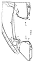
- FIG. 1 shows a section through an aircraft passenger cabin looking in the direction of flight. In the picture only the left part of the upper cabin area can be seen. The right half of this area, which is symmetrical to the central plane 4 of the cabin, is not shown.
- a fuselage structure 1 a central luggage rack 2 with a flap 8 and a side luggage rack 3 with a flap 9.
- the area between the luggage racks 2, 3 is closed at the top by ceiling elements 5 of the same design which are joined together in the longitudinal direction.
- ceiling elements 5 Like the ceiling elements 5, a large number of luggage racks 2, 3 are also lined up in the longitudinal direction of the cabin.
- a longitudinal corridor is located below each of the ceiling elements 5.
- a fluorescent lamp 6 is assigned to each ceiling element 5 and extends essentially over the entire adjacent edge of the element 5.
- the ceiling element 5 is approximately parabolically curved, its less strongly curved area extending towards the fluorescent lamp 6.
- the beam path of the light emanating from the lamp 6 is partially shown.
- the flap 8 of the central luggage rack 2 arranged below the fluorescent lamp 6 acts as a screen, so that only the ceiling element 5 and the side luggage rack 3 are illuminated directly.
- a reflector 7 is arranged on the side of the fluorescent lamp 6 facing away from the ceiling element 5, which reflector reflects the light coming from the fluorescent lamp 6 towards the ceiling element 5.
- the flaps 8 and 9 each have an inclined position such that their mutual distance increases upwards.
- Each ceiling element 5 is bounded in the longitudinal direction of the aircraft to the rear and to the front by a downwardly drawn edge 10 of small width.
- Fig. 2 shows the combination of FIG. 1 with the aforementioned elements, but with opened luggage flaps 8 and 9.
- the luggage rack 2 is closed at the top by a wall 2a, with a gap between the front edge and the upper edge of the luggage flap 8 in the open state of width b.
- the picture shows that in the relevant positions of the flaps 8 and 9, the interior of the luggage racks 2 and 3 are well illuminated, which makes it easier to store luggage. Thus light falls through the gap between the flap 8 and the wall 2a into the interior of the luggage rack 2.
- the luggage rack 3 is illuminated by the ceiling element 5 with predominantly indirect light. In the event that the luggage rack 2 is closed, the rack 3 also receives direct light from the fluorescent lamp 6.
- FIG. 3 again shows a section according to FIG. 1 with the fuselage structure 1, the luggage racks 2 and 3 with the flaps 8 and 9, the ceiling element 5, the fluorescent lamp 6 and the reflector 7.
- the passenger seats 20 are arranged inside the passenger compartment 14, of which only the upper areas of the backrests can be seen here.
- Below the ceiling element 5 is the longitudinal aisle 16.
- the light coming from the fluorescent lamp 6 is reflected by the convexly shaped flap 9 as direct light 15 onto the passage 16 of the passenger compartment 14.
- the fluorescent lamp 6 is arranged so that this is still possible when the flap 8 is open. Furthermore, the light emitted onto the opened flap 8 and onto the flap 9 is reflected by these towards the ceiling elements 5. If the flap 9 is open, it is ensured that the interior of the luggage rack 3 is illuminated by means of the direct light 15.
- the flaps 8 and 9 and the ceiling element 5 have a coating 19 such that the brightness of the reflected indirect and direct light 13, 15 due to the degree of reflection the applied coating 19 is determined.
- the reflector 7 can be positioned in two axes with respect to the fluorescent lamp 6 in such a way that the corresponding amount of light is emitted from the ceiling elements 5, 11 and the flaps 8, 9.
- the reflector either has the shape of a half-shell or has differently shaped surface sections that emit the light in different directions.
- the fluorescent lamp 6 with the reflector 7 is expediently arranged above and deep behind the right luggage rack 2 in such a way that it cannot be seen directly at normal standing height.
- Fig. 1 the position of the heads of people with 1.7 or 1.8 m height is shown according to arrow 3a.
- Fig. 4 shows another embodiment of the invention, wherein the fluorescent lamp 6 is arranged near the side luggage rack 3.
- This embodiment also consists in that a fluorescent lamp 6 is provided for each ceiling element 11 and the ceiling element 11 is approximately parabolically curved, with its less strongly curved area extending towards the fluorescent lamp 6 and the fluorescent lamp 6 being covered by a diaphragm 12 such that in essential indirect light penetrates into the cabin, again a reflector is provided, which is not shown here.
- the inclined position of the luggage flaps 8 and 9 introduced for optical reasons, has the advantageous effect, in particular in the case of the side luggage rack 3, that the items of luggage stored here show greater stability. As a result, there is less tendency for these pieces to fall out of the luggage rack 3.
- FIG. 5 shows the course of the contour line of the ceiling element 5 according to FIGS. 1 and 2 with the center of the fluorescent lamp 6 related to this.
- the curve shown was experimentally determined and gives optimal lighting conditions in the ceiling-luggage rack combination shown in Figures 1, 2 and 3.
- FIG. 6 shows the coordinates of the curve according to FIG. 5 in a table.
Landscapes
- Engineering & Computer Science (AREA)
- Aviation & Aerospace Engineering (AREA)
- Mechanical Engineering (AREA)
- Arrangements Of Lighting Devices For Vehicle Interiors, Mounting And Supporting Thereof, Circuits Therefore (AREA)
- Vehicle Step Arrangements And Article Storage (AREA)
Abstract
Description
Die Erfindung bezieht sich auf eine Kombination nach dem Oberbegriff des Anspruchs 1.The invention relates to a combination according to the preamble of claim 1.
Derartige Kombinationen bilden den oberen Bereich der Passagierkabine eines Flugzeuges und bestehen im wesentlichen aus den Gepäckablagen sowie der Decke, die den oberen Bereich der Kabinen-Innenverkleidung bildet. Im Bereich der Decke bzw. der Gepäckablagen sind auch die Leuchtstofflampen für die Beleuchtung der Kabine angeordnet. Eine Passagierkabine mit zwei Längsgängen weist eine mittlere und zwei seitliche mit Klappen versehene Gepäckablagen auf. Zur Beleuchtung werden mit lichtdurchlässigen Abdeckungen versehene Leuchtstofflampen verwendet, wovon je Längsgang zwei sog. Lichtbänder angeordnet sind. Die seitlichen Gepäckablagen sind aus Platzgründen so ausgebildet, daß sie nur kleine Gepäckstücke sicher aufnehmen können. Insbesondere aufgrund der relativ hohen Anzahl von Leuchtstofflampen ergeben sich hohe Herstellkosten der besagten Kombination.Such combinations form the upper area of the passenger cabin of an aircraft and essentially consist of the luggage racks and the ceiling, which forms the upper area of the cabin interior lining. The fluorescent lamps for lighting the cabin are also arranged in the area of the ceiling and the luggage racks. A passenger cabin with two longitudinal aisles has a central and two side luggage racks provided with flaps. Fluorescent lamps with translucent covers are used for lighting, of which two so-called light strips are arranged per longitudinal aisle. For reasons of space, the side luggage racks are designed so that they can only hold small pieces of luggage. In particular due to the relatively high number of fluorescent lamps, this combination has high manufacturing costs.
Durch die US-A-3,535,505 ist ein Leuchtstofflampensystem bekannt, wie es beispielsweise für große Flugzeugpassagierkabinen verwendbar ist, wobei Reflektoren zur Beseitigung von Endschatten dienen. Hierdurch werden die jeweils zwischen zwei Leuchtstofflampen befindlichen Stoßbereiche aufgehellt. Dieser Druckschrift ist jedoch nirgends ein Hinweis zu entnehmen, die Kabinendecke und die Gepäckablagen so auszubilden, daß die Anzahl der Leuchtstofflampen reduziert wird.From US-A-3,535,505 a fluorescent lamp system is known, such as can be used for example for large aircraft passenger cabins, reflectors being used to remove end shadows. This brightens the impact areas between two fluorescent lamps. Nowhere in this document is there a hint to design the cabin ceiling and the luggage racks so that the number of fluorescent lamps is reduced.
Demgemäß liegt der Erfindung die Aufgabe zugrunde, eine gattungsgemäße Kombination derart auszubilden, daß je Längsgang ein Lichtband eingespart und die hierdurch bedingte geringere Beleuchtungsdichte durch optisch wirksame Maßnahmen weitgehend ausgeglichen wird.Accordingly, the invention has for its object to provide a generic combination such that a light band is saved per longitudinal aisle and the resulting lower illumination density is largely compensated by optically effective measures.
Diese Aufgabe wird bei einer gattungsgemäßen Kombination durch die kennzeichnenden Merkmale des Patentanspruchs 1 gelöst.This object is achieved in a generic combination by the characterizing features of claim 1.
Dabei ist insbesondere von Vorteil, daß im Gefolge des Wegfalls der Hälfte aller Leuchtstofflampen auch eine entsprechende Anzahl von Vorschaltgeräten entfällt. Hierdurch ergibt sich nicht nur eine Reduzierung der Herstellkosten, sondern auch eine erhebliche Gewichtsreduzierung.It is particularly advantageous that, in the wake of the elimination of half of all fluorescent lamps, a corresponding number of ballasts is also eliminated. This not only results in a reduction in manufacturing costs, but also in a considerable reduction in weight.
Vorteilhafte Weiterbildungen der Erfindung sind in den Unteransprüchen angegeben.Advantageous developments of the invention are specified in the subclaims.
So besteht ein Vorteil der Ausgestaltungen nach den Ansprüchen 2 und 3 darin, daß die Kombination den Gegebenheiten des Flugzeuges gestalterisch angepaßt werden kann.An advantage of the configurations according to
Ein Vorteil der Ausgestaltung nach Anspruch 4 besteht darin, daß sich günstige Reflexionswinkel ergeben und außerdem der gesamte Deckenbereich optisch einen geräumigen Eindruck vermittelt.An advantage of the embodiment according to
Die Erfindung ist in der Zeichnung dargestellt und in der Beispielbeschreibung näher erläutert. Es zeigen
- Fig. 1
- einen Schnitt durch eine Decken-Gepäckablagen-Kombination mit zentral angeordneten Leuchtstofflampen,
- Fig. 2
- eine Kombination nach Fig. 1 mit geöffneten Gepäckklappen,
- Fig. 3
- einen Schnitt, entsprechend Fig. 1, mit einer Darstellung der Lichtverhältnisse,
- Fig. 4
- eine Kombination mit seitlich angeordneten Leuchtstofflampen,
- Fig. 5
- den Kurvenverlauf des Deckenelementes nach Fig. 1 und
- Fig. 6
- die Tabelle der Koordinaten des Kurvenverlaufes nach Fig. 4.
- Fig. 1
- a section through a ceiling-luggage rack combination with centrally arranged fluorescent lamps,
- Fig. 2
- 1 with open luggage flaps,
- Fig. 3
- 2 shows a section corresponding to FIG. 1 with a representation of the lighting conditions,
- Fig. 4
- a combination with fluorescent lamps arranged on the side,
- Fig. 5
- the curve of the ceiling element according to Fig. 1 and
- Fig. 6
- the table of the coordinates of the curve according to FIG. 4.
Fig. 1 zeigt mit Blick in Flugrichtung einen Schnitt durch eine Flugzeug-Passagierkabine. Im Bild ist nur der linke Teil des oberen Kabinenbereiches zu sehen. Die zur Mittelebene 4 der Kabine symmetrische rechte Hälfte dieses Bereiches ist nicht dargestellt. Man sieht eine Rumpfstruktur 1, eine zentrale Gepäckablage 2 mit einer Klappe 8 und eine seitliche Gepäckablage 3 mit einer Klappe 9. Der zwischen den Gepäckablagen 2,3 befindliche Bereich wird nach oben durch in Längsrichtung aneinandergefügte gleich ausgebildete Deckenelemente 5 abgeschlossen. Wie die Deckenelemente 5 so ist auch eine Vielzahl von Gepäckablagen 2,3 in Kabinenlängsrichtung aneinandergereiht. Unterhalb der Deckenelemente 5 befindet sich jeweils ein Längsgang. Jedem Deckenelement 5 ist eine Leuchtstofflampe 6 zugeordnet, die sich im wesentlichen über die gesamte angrenzende Kante des Elementes 5 erstreckt. Das Deckenelement 5 ist annähernd parabolisch gekrümmt, wobei sich dessen weniger stark gekrümmter Bereich zur Leuchtstofflampe 6 hin erstreckt. Der Strahlengang des von der Lampe 6 ausgehenden Lichtes ist teilweise eingezeichnet. Hierdurch ist zu erkennen, daß die unterhalb der Leuchtstofflampe 6 angeordnete Klappe 8 der zentralen Gepäckablage 2 als Blende wirkt, so daß nur das Deckenelement 5 und die seitliche Gepäckablage 3 direkt angestrahlt werden. Zur Erhöhung der Lichtausbeute ist auf der dem Deckenelement 5 abgewandten Seite der Leuchtstofflampe 6 ein Reflektor 7 angeordnet, der das von der Leuchtstofflampe 6 ausgehende Licht zum Deckenelement 5 hin reflektiert. Um die Wirksamkeit der Beleuchtung weiter zu erhöhen, weisen die Klappen 8 und 9 jeweils eine Schräglage derart auf, daß ihr gegenseitiger Abstand nach oben zunimmt. Auf diese Weise wird eine indirekte Beleuchtung der Kabine erreicht, wobei das nach unten in die Kabine fallende Licht im wesentlichen von den Deckenelementen 5 und den Klappen 8,9 ausgeht. Jedes Deckenelement 5 wird in Flugzeug-Längsrichtung nach hinten und nach vorn jeweils durch eine nach unten gezogene Kante 10 von geringer Breite begrenzt.1 shows a section through an aircraft passenger cabin looking in the direction of flight. In the picture only the left part of the upper cabin area can be seen. The right half of this area, which is symmetrical to the
Fig. 2 zeigt die Kombination nach Fig. 1 mit den vorgenannten Elementen, jedoch mit geöffneten Gepäckklappen 8 und 9. Die Gepäckablage 2 ist nach oben durch eine Wandung 2a abgeschlossen, wobei zwischen deren Vorderkante und der Oberkante der Gepäckklappe 8 in geöffnetem Zustand ein Spalt von der Breite b besteht. Das Bild zeigt, daß in den betreffenden Stellungen der Klappen 8 und 9 die Innenräume der Gepäckablagen 2 und 3 gut ausgeleuchtet sind, wodurch die Ablage von Gepäck erleichtert wird. So fällt Licht durch den zwischen der Klappe 8 und der Wandung 2a bestehenden Spalt ins Innere der Gepäckablage 2. Die Gepäckablage 3 wird vom Deckenelement 5 her mit vorwiegend indirektem Licht angestrahlt. Im Falle, daß die Gepäckablage 2 geschlossen ist, erhält die Ablage 3 auch direktes Licht von der Leuchtstofflampe 6 her.Fig. 2 shows the combination of FIG. 1 with the aforementioned elements, but with opened
Fig. 3 zeigt wieder einen Schnitt gemäß Fig. 1 mit der Rumpfstruktur 1, den Gepäckablagen 2 und 3 mit den Klappen 8 und 9, dem Deckenelement 5, der Leuchtstofflampe 6 sowie dem Reflektor 7. Innerhalb des Passagierraumes 14 sind die Passagiersitze 20 angeordnet, wovon hier nur die oberen Bereiche der Rückenlehnen zu sehen sind. Unterhalb des Deckenelementes 5 befindet sich der mit 16 bezeichnete Längsgang. Das von der Leuchtstofflampe 6 ausgehende Licht wird von der konvex geformten Klappe 9 als direktes Licht 15 auf den Durchgang 16 des Passagierraumes 14 reflektiert. Die Leuchtstofflampe 6 ist so angeordnet, daß dies auch noch bei geöffneter Klappe 8 möglich ist. Weiterhin wird das auf die geöffnete Klappe 8 und auf die Klappe 9 abgestrahlte Licht von diesen zu den Deckenelementen 5 reflektiert. Ist die Klappe 9 geöffnet, so ist gewährleistet, daß der Innenraum der Gepäckablage 3 mittels des direkten Lichtes 15 ausgeleuchtet wird.3 again shows a section according to FIG. 1 with the fuselage structure 1, the luggage racks 2 and 3 with the
Die Klappen 8 und 9 sowie das Deckenelement 5 weisen eine Beschichtung 19 derart auf, daß die Helligkeit des reflektierten indirekten und direkten Lichtes 13,15 durch den Reflexionsgrad der aufgetragenen Beschichtung 19 bestimmt ist. Der Reflektor 7 ist derart in zwei Achsen zur Leuchtstofflampe 6 positionierbar, daß von diesem jeweils die entsprechende Lichtmenge auf die Deckenelemente 5,11 und auf die Klappen 8,9 abgestrahlt wird.The
Eine andere Ausgestaltung der Erfindung besteht darin, daß der Reflektor entweder die Form einer Halbschale aufweist oder über unterschiedlich geformte Flächenabschnitte verfügt, die das Licht in unterschiedliche Richtungen abstrahlen.Another embodiment of the invention is that the reflector either has the shape of a half-shell or has differently shaped surface sections that emit the light in different directions.
Die Leuchtstofflampe 6 mit dem Reflektor 7 ist zweckmäßig derart oberhalb und tief hinter der rechten Gepäckablage 2 angeordnet, daß diese in normaler Stehhöhe nicht direkt einsehbar ist. In Fig. 1 ist die Position der Köpfe von Personen mit 1,7 bzw. 1,8 m Körpergröße entsprechend Pfeil 3a dargestellt.The
Fig. 4 zeigt eine andere Ausgestaltung der Erfindung, wobei die Leuchtstofflampe 6 nahe der seitlichen Gepäckablage 3 angeordnet ist. Diese Ausgestaltung besteht ebenfalls darin, daß je Deckenelement 11 eine Leuchtstofflampe 6 vorgesehen ist und das Deckenelement 11 annähernd parabolisch gekrümmt ist, wobei sich dessen weniger stark gekrümmter Bereich zur Leuchtstofflampe 6 hin erstreckt und die Leuchtstofflampe 6 derart durch eine Blende 12 abgedeckt ist, daß im wesentlichen indirektes Licht in die Kabine dringt, wobei wieder ein Reflektor vorgesehen ist, der hier jedoch nicht gezeigt ist. Die aus optischen Erwägungen eingeführte Schräglage der Gepäckklappen 8 und 9 hat insbesondere bei der seitlichen Gepäckablage 3 die vorteilhafte Wirkung, daß die hier abgelegten Gepäckstücke eine höhere Standfestigkeit zeigen. Hierdurch besteht eine geringere Neigung dieser Stücke, aus der Gepäckablage 3 herauszufallen.Fig. 4 shows another embodiment of the invention, wherein the
Fig. 5 zeigt den Verlauf der Konturlinie des Deckenelementes 5 nach den Figuren 1 und 2 mit dem hierzu in Beziehung gesetzten Mittelpunkt der Leuchtstofflampe 6. Die gezeigte Kurve wurde experimentell ermittelt und ergibt optimale Lichtverhältnisse bei der in den Figuren 1, 2 und 3 gezeigten Decken-Gepäckablagen-Kombination.FIG. 5 shows the course of the contour line of the ceiling element 5 according to FIGS. 1 and 2 with the center of the
Fig. 6 zeigt in einer Tabelle die Koordinaten der Kurve nach Fig.5.6 shows the coordinates of the curve according to FIG. 5 in a table.
Die vorbeschriebenen Lösungen sind nicht an eine Leuchtstofflampe als Lichtquelle gebunden. Es ist darüber hinaus jede andere geeignete Lichtquelle verwendbar.The solutions described above are not tied to a fluorescent lamp as a light source. Any other suitable light source can also be used.
Die Erfindung ist nicht auf die dargestellten und beschriebenen Beispielausführungen beschränkt. Sie erstreckt sich vielmehr auf alle Ausgestaltungen, die im Rahmen der Ansprüche denkbar sind.The invention is not restricted to the exemplary embodiments shown and described. Rather, it extends to all configurations that are conceivable within the scope of the claims.
Claims (15)
- A ceiling/luggage compartment combination for an aircraft passenger cabin with two longitudinal gangways (16), consisting of a middle (2) and two side luggage compartments (3), which are each arranged in the upper region of the cabin, in which the ceiling consists of individual curved ceiling elements (5, 11) which extend substantially between the upper edges of the luggage compartments (2,3) and the combination comprises tubular fluorescent lights (6) running longitudinally of the aircraft and each associated with a ceiling element (5,11), characterised in that the ceiling element (5,11) is curved substantially parabolically, its less strongly curved region extending to the fluorescent light (6) and the fluorescent light (6) is covered by a shield (12) such that essentially indirect light enters the cabin, there being arranged on the side of the fluorescent light (6) remote from the ceiling element (5,11) a reflector (7), which reflects the light emitted by the fluorescent light (6) predominantly on to the ceiling element (5,11).
- A combination according to claim 1, characterised in that the fluorescent light (6) is arranged above the middle luggage compartment (2), the luggage compartment (2) acting as a shield.
- A combination according to claim 1, characterised in that the fluorescent light (6) is arranged adjacent to the side luggage compartment (3), the entry of direct light to the cabin being avoided by means of a shield (12).
- A combination according to any one of claims 1 to 3, characterised in that the front parts of the luggage flaps (8,9) have an oblique position such that their mutual spacing increases upwardly.
- A combination according to any one of claims 1 to 4, characterised in that between the front edge of an upper partition (2a) and the upper edge of the luggage flap (8) there occurs in the open condition a gap of width b.
- A combination according to any one of claims 1 to 5, characterised in that the light from the fluorescent light (6) is reflected as direct light (15) from the convex flap (9) closing the luggage compartment (3) into a gangway (16) of the passenger space (14).
- A combination according to any one of claims 1 to 6, characterised in that the light radiated onto the open flap (8) and onto the flap (9) is reflected by these to the ceiling elements (5,11).
- A combination according to any one of claims 1 to 7, characterised in that the interior of the luggage compartment (3) is illuminated by means of the direct light (15) when the flap (9) is open.
- A combination according to any one of claims 1 to 8, characterised in that the luminosity of the reflected indirect and direct light (13,15) is determined by the degree of reflection of a correspondingly selected coating (19) applied to the ceiling elements (5, 11) and the flap (8,9).
- A combination according to any one of claims 1 to 9, characterised in that the reflector (7) can be positioned in two axes relative to the fluorescent light (6) so that in each case the corresponding amount of light is radiated on to the ceiling elements (5,11) and onto the flap (8,9).
- A combination according to any one of claims 1 to 10, characterised in that reflector either has the shape of a half dish or has at its disposal surface sections of differing shapes, which radiate the light in different directions.
- A combination according to any one of claims 1 to 11, characterised in that the fluorescent light (6) is so arranged with the reflector (7) above and well behind the right-hand luggage compartment (2) that the fluorescent light (6) is not directly visible at normal standing height.
- A combination according to any one of claims 1 to 12, characterised in that the outline of the ceiling element (5,11) has the co-ordinates according to the Table of Fig. 5.
- A combination according to claim 13 characterised in that the outline of the ceiling elements (5,11) lies within a band which results if the co-ordinates according to the Table are taken according to Fig. 5 plus/minus 5%.
- A combination according to any one of claims 1 to 14, characterised in that instead of the fluorescent light (6) there is used a light source of any desired type.
Applications Claiming Priority (4)
| Application Number | Priority Date | Filing Date | Title |
|---|---|---|---|
| DE3903491 | 1989-02-06 | ||
| DE3903491 | 1989-02-06 | ||
| DE3904375 | 1989-02-14 | ||
| DE3904375A DE3904375A1 (en) | 1989-02-14 | 1989-02-14 | Ceiling-luggage rack combination for passenger cabin of aircraft |
Publications (2)
| Publication Number | Publication Date |
|---|---|
| EP0408709A1 EP0408709A1 (en) | 1991-01-23 |
| EP0408709B1 true EP0408709B1 (en) | 1993-06-09 |
Family
ID=25877505
Family Applications (1)
| Application Number | Title | Priority Date | Filing Date |
|---|---|---|---|
| EP90902153A Expired - Lifetime EP0408709B1 (en) | 1989-02-06 | 1990-02-03 | Ceiling/luggage-rack combination for the passenger cabin of an aircraft |
Country Status (4)
| Country | Link |
|---|---|
| US (1) | US5129597A (en) |
| EP (1) | EP0408709B1 (en) |
| DE (1) | DE59001679D1 (en) |
| WO (1) | WO1990008674A1 (en) |
Cited By (2)
| Publication number | Priority date | Publication date | Assignee | Title |
|---|---|---|---|---|
| DE19926776B4 (en) * | 1999-06-11 | 2004-07-22 | Airbus Deutschland Gmbh | Functional unit for passenger cabins, in particular for aircraft passenger cabins |
| DE102007001702A1 (en) * | 2007-01-11 | 2008-07-17 | Airbus Deutschland Gmbh | Lighting device for an aircraft |
Families Citing this family (86)
| Publication number | Priority date | Publication date | Assignee | Title |
|---|---|---|---|---|
| US5201831A (en) * | 1991-11-15 | 1993-04-13 | Atr International, Inc. | Aircraft interior shell |
| US5347434A (en) * | 1992-07-06 | 1994-09-13 | Mcdonnell Douglas Corporation | Aircraft bag-rack with an illuminated handrail |
| DE9214592U1 (en) * | 1992-10-28 | 1993-02-11 | Deutsche Aerospace Airbus GmbH, 2000 Hamburg | Overhead luggage rack with lowerable tray, particularly for use in passenger aircraft |
| US5395074A (en) * | 1993-03-10 | 1995-03-07 | Health Tecna Aerospace Company A Unit Of Ciba-Geigy | Retrofit bezel assembly |
| US5456529A (en) * | 1993-12-30 | 1995-10-10 | The Boeing Company | Powered overhead stowage bin |
| US5549258A (en) * | 1994-12-23 | 1996-08-27 | Heath Tecna Aerospace Company | Retrofit luggage bin assembly compatible with existing aircraft bin supports |
| US6062509A (en) * | 1994-12-23 | 2000-05-16 | Hexcel Corporation | Retrofit centerline luggage bin assemblies compatible with existing aircraft bin supports |
| US5687929A (en) * | 1995-06-29 | 1997-11-18 | Hexcel Corporation | Extensions for storage bins |
| DE19540929C2 (en) * | 1995-11-03 | 1997-08-14 | Daimler Benz Aerospace Airbus | Luggage rack in a passenger cabin, especially in a commercial aircraft |
| EP0795469A1 (en) * | 1996-03-15 | 1997-09-17 | DaimlerChrysler Aerospace Airbus Gesellschaft mit beschränkter Haftung | Evacuation and guidance lightning system for the occupants of an aircraft cabin |
| DE19633469C1 (en) * | 1996-08-20 | 1997-09-04 | Daimler Benz Aerospace Airbus | Device for holding overhead baggage compartments in aircraft passenger cabins |
| EP0932548B1 (en) | 1996-10-22 | 2003-01-22 | The Boeing Company | Airplane with unswept slotted cruise wing airfoil |
| US5842668A (en) * | 1997-02-27 | 1998-12-01 | Hexcel Corporation | Quick fit overhead stowage compartment |
| DE19733229C1 (en) * | 1997-08-01 | 1998-10-29 | Happich Fahrzeug & Ind Teile | Air-duct cover light for large capacity vehicle especially omnibus with bulb carrier and shade |
| US5934615A (en) * | 1997-08-25 | 1999-08-10 | Hexcel Corporation | Luggage bins with articulating mechanism |
| US6003813A (en) * | 1997-09-10 | 1999-12-21 | The Boeing Company | Escape systems for aircraft overhead rest areas |
| US6152400A (en) * | 1997-09-10 | 2000-11-28 | The Boeing Company | Aircraft lower lobe sleeping compartment |
| US6173921B1 (en) | 1998-12-21 | 2001-01-16 | The Boeing Company | Airplane passenger privacy and support apparatus |
| DE19920404A1 (en) * | 1999-05-04 | 2000-11-09 | Hella Innenleuchten Systeme Gm | Lamp, e.g. for vehicle interior; has line or curve of photodiodes and reflector with shallow area nearer photodiode and steep area further from photodiode, to reflect part of beam from both areas |
| US6398163B1 (en) * | 1999-06-10 | 2002-06-04 | Jerry Welch | Enhanced luggage bin system |
| EP1083089B9 (en) * | 1999-09-11 | 2007-08-08 | Dr.Ing. h.c.F. Porsche Aktiengesellschaft | Orientation lighting in a vehicle |
| US6290175B1 (en) | 1999-10-20 | 2001-09-18 | Hexcel Corporation | Bin extension for a vehicle |
| US6622965B1 (en) * | 1999-12-20 | 2003-09-23 | Interami Ltd. | Aircraft luggage rack |
| US6350048B1 (en) * | 2000-02-03 | 2002-02-26 | William H. Stanton | Passenger lighting system for mass transit vehicle |
| DE10127879A1 (en) * | 2000-06-15 | 2002-07-18 | Airbus Gmbh | Passenger cabin for commercial aircraft incorporates at least one modular interior fitting building block which can be assembled in modular fashion for at least one cross sectional size |
| US6536710B1 (en) * | 2002-02-06 | 2003-03-25 | The Boeing Company | Overhead lattice support structure |
| US6899299B2 (en) * | 2002-07-26 | 2005-05-31 | The Boeing Company | Luggage bins and aircraft passenger cabin ceilings |
| US6837460B2 (en) | 2003-02-28 | 2005-01-04 | The Boeing.Company | Integrated conformal vehicle interior linings |
| US7059563B2 (en) * | 2003-06-03 | 2006-06-13 | The Boeing Company | Systems, apparatuses, and methods for moving aircraft control surfaces |
| US7380752B2 (en) * | 2003-10-17 | 2008-06-03 | The Boeing Company | Aircraft interior architecture |
| US7252267B2 (en) * | 2003-10-17 | 2007-08-07 | The Boeing Company | Aircraft archway architecture |
| US6799739B1 (en) | 2003-11-24 | 2004-10-05 | The Boeing Company | Aircraft control surface drive system and associated methods |
| US6978971B1 (en) * | 2004-06-15 | 2005-12-27 | The Boeing Company | Methods and apparatuses for controlling airflow proximate to engine/airfoil systems |
| US7494094B2 (en) | 2004-09-08 | 2009-02-24 | The Boeing Company | Aircraft wing systems for providing differential motion to deployable lift devices |
| US7264206B2 (en) | 2004-09-30 | 2007-09-04 | The Boeing Company | Leading edge flap apparatuses and associated methods |
| US7338018B2 (en) | 2005-02-04 | 2008-03-04 | The Boeing Company | Systems and methods for controlling aircraft flaps and spoilers |
| US7455263B2 (en) * | 2005-04-22 | 2008-11-25 | The Boeing Company | Airplane interior systems |
| US7300021B2 (en) * | 2005-05-20 | 2007-11-27 | The Boeing Company | Aerospace vehicle fairing systems and associated methods |
| US7721999B2 (en) | 2005-05-20 | 2010-05-25 | The Boeing Company | Aerospace vehicle fairing systems and associated methods |
| US7665692B2 (en) * | 2005-10-28 | 2010-02-23 | Airbus | Baggage bin door and baggage bin |
| US8011618B2 (en) * | 2005-10-28 | 2011-09-06 | Airbus | Storage device for baggage for an aircraft cabin |
| US20070139941A1 (en) * | 2005-11-16 | 2007-06-21 | Bryan Eric A | Ceiling illumination for aircraft interiors |
| US7708231B2 (en) | 2005-11-21 | 2010-05-04 | The Boeing Company | Aircraft trailing edge devices, including devices having forwardly positioned hinge lines, and associated methods |
| US7895955B2 (en) * | 2006-03-15 | 2011-03-01 | Ft Products, Llc | Shelf system |
| DE102006032249B4 (en) * | 2006-07-12 | 2013-11-07 | Airbus Operations Gmbh | Invisible emergency lighting for an aircraft cabin |
| US7893645B2 (en) * | 2006-08-25 | 2011-02-22 | The Boeing Company | System and method for compartment control |
| DE102006048376B4 (en) * | 2006-10-12 | 2010-04-15 | Airbus Deutschland Gmbh | Self-supporting cabin structure |
| US7717593B2 (en) * | 2007-06-08 | 2010-05-18 | The Boeing Company | Device for improved illumination efficiency |
| US7717594B2 (en) * | 2007-06-14 | 2010-05-18 | The Boeing Company | Compact illumination device |
| US7540639B2 (en) * | 2007-10-22 | 2009-06-02 | The Boeing Company | Cross bin illumination system |
| US7954769B2 (en) | 2007-12-10 | 2011-06-07 | The Boeing Company | Deployable aerodynamic devices with reduced actuator loads, and related systems and methods |
| US7766282B2 (en) | 2007-12-11 | 2010-08-03 | The Boeing Company | Trailing edge device catchers and associated systems and methods |
| US8083280B2 (en) * | 2008-02-20 | 2011-12-27 | Magna International Inc. | Modular storage compartment for vehicle |
| US8167243B2 (en) * | 2008-09-29 | 2012-05-01 | Embraer S.A. | Systems and methods to provide optical enlargement of passenger interior cabin space |
| US8382045B2 (en) | 2009-07-21 | 2013-02-26 | The Boeing Company | Shape-changing control surface |
| WO2011106695A1 (en) | 2010-02-25 | 2011-09-01 | B/E Aerospace, Inc. | Led lighting element |
| US20110255296A1 (en) * | 2010-04-20 | 2011-10-20 | Be Intellectual Property, Inc. | Aircraft ceiling module with integrated lighting, valences and wiring |
| EP2492194B1 (en) | 2011-02-24 | 2014-06-04 | Thk Co., Ltd. | Overhead baggage compartment |
| DE102011013206A1 (en) * | 2011-03-05 | 2012-09-06 | Diehl Aerospace Gmbh | Area light, in particular for Flugzugkabinen |
| DE102011102364A1 (en) | 2011-05-24 | 2012-11-29 | Airbus Operations Gmbh | Cantilever cabin structure segment |
| US10029794B2 (en) | 2012-02-14 | 2018-07-24 | C&D Zodiac, Inc. | Outboard rotating pivot bin assembly |
| US9162617B2 (en) | 2012-02-14 | 2015-10-20 | C&D Zodiac, Inc. | Pivot bin assembly |
| US9365291B2 (en) | 2012-02-14 | 2016-06-14 | C&D Zodiac, Inc. | Passenger service unit pod assembly |
| US9789963B2 (en) | 2012-02-14 | 2017-10-17 | C&D Zodiac, Inc. | Pivot bin assembly with minimal force required for closing |
| US8955805B2 (en) | 2012-02-14 | 2015-02-17 | C&D Zodiac, Inc. | Pivot bin assembly |
| WO2014011806A2 (en) * | 2012-07-11 | 2014-01-16 | B/E Aerospace, Inc. | An aircraft washlight system |
| USD784905S1 (en) | 2013-02-12 | 2017-04-25 | C&D Zodiac, Inc. | Storage bin for aircraft |
| WO2014165821A1 (en) * | 2013-04-05 | 2014-10-09 | B/E Aerospace, Inc. | Overhead equipment stowage pod for an aircraft interior |
| JP6206753B2 (en) * | 2013-04-12 | 2017-10-04 | パナソニックIpマネジメント株式会社 | Lighting system |
| US9327834B2 (en) * | 2013-10-04 | 2016-05-03 | Embraer S.A. | Overhead bin system |
| DE102013021108A1 (en) * | 2013-12-11 | 2015-06-11 | Airbus Operations Gmbh | Aircraft luggage system with a luggage compartment and an additional luggage compartment |
| DE102014202783B4 (en) | 2014-02-14 | 2022-02-24 | Airbus Operations Gmbh | aircraft cabin layout |
| DE102014202751B4 (en) | 2014-02-14 | 2020-03-19 | Airbus Operations Gmbh | Interior trim arrangement for a passenger cabin of a vehicle |
| DE102014202753A1 (en) * | 2014-02-14 | 2015-08-20 | Airbus Operations Gmbh | Aircraft cabin arrangement |
| KR101601837B1 (en) * | 2014-10-10 | 2016-03-10 | 주식회사 서연이화 | mood light device of a vehicle |
| USD784904S1 (en) | 2015-02-02 | 2017-04-25 | C&D Zodiac, Inc. | Aircraft passenger service unit |
| USD875641S1 (en) | 2015-02-02 | 2020-02-18 | C&D Zodiac, Inc. | Personal service unit |
| CA3003753C (en) | 2015-12-07 | 2020-01-07 | C&D Zodiac, Inc. | Storage bin with luggage positioning protrusions |
| US10214287B2 (en) * | 2016-02-26 | 2019-02-26 | The Boeing Company | Vehicle cabin wayfinding assembly |
| DE102016205100A1 (en) * | 2016-03-29 | 2017-11-09 | Siemens Aktiengesellschaft | Lighting device and method for illuminating a passenger compartment ceiling of a vehicle |
| EP3436352B1 (en) * | 2016-04-01 | 2021-03-31 | B/E Aerospace, Inc. | Hinge for enlarging the volume of an aircraft storage bin |
| CN111065578B (en) | 2017-07-17 | 2023-08-01 | 哈珀工程公司 | Integrated storage bin assembly |
| US10377492B1 (en) * | 2018-02-13 | 2019-08-13 | The Boeing Company | Illuminating ceiling systems and methods for an internal cabin of a vehicle |
| US11046435B2 (en) * | 2018-08-24 | 2021-06-29 | The Boeing Company | Keep-out assembly for an overhead stowage bin assembly and method of closing out a maintenance area above a stowage bin assembly |
| DE102020108277A1 (en) * | 2020-03-25 | 2021-09-30 | Airbus Operations Gmbh | Movement device with locking actuator, overhead locker with movement device and vehicle with overhead locker |
| DE102020109169A1 (en) * | 2020-04-02 | 2021-10-07 | Airbus Operations Gmbh | Vehicle area with luggage compartment with enlarged storage space, and method for installing and removing a ceiling panel above a luggage compartment |
Family Cites Families (6)
| Publication number | Priority date | Publication date | Assignee | Title |
|---|---|---|---|---|
| US2198579A (en) * | 1934-04-14 | 1940-04-23 | Budd Edward G Mfg Co | Illumination system |
| US2595858A (en) * | 1946-03-09 | 1952-05-06 | American Car & Foundry Co | Railway car |
| US2582738A (en) * | 1949-07-08 | 1952-01-15 | Patent License Corp | Interior illumination system for vehicles and recessed twin beam fixtures therefor |
| US3535505A (en) * | 1968-03-14 | 1970-10-20 | Bruce Ind Inc | Fluorescent lighting system with reflectors for eliminating end shadows |
| US4799631A (en) * | 1987-02-18 | 1989-01-24 | Atr International, Inc. | Aircraft shell module |
| DE3741164C1 (en) * | 1987-12-04 | 1989-07-20 | Airbus Gmbh | Luggage rack for vehicles, in particular airplanes |
-
1990
- 1990-02-03 US US07/582,867 patent/US5129597A/en not_active Expired - Lifetime
- 1990-02-03 EP EP90902153A patent/EP0408709B1/en not_active Expired - Lifetime
- 1990-02-03 WO PCT/DE1990/000074 patent/WO1990008674A1/en active IP Right Grant
- 1990-02-03 DE DE9090902153T patent/DE59001679D1/en not_active Expired - Fee Related
Cited By (3)
| Publication number | Priority date | Publication date | Assignee | Title |
|---|---|---|---|---|
| DE19926776B4 (en) * | 1999-06-11 | 2004-07-22 | Airbus Deutschland Gmbh | Functional unit for passenger cabins, in particular for aircraft passenger cabins |
| DE102007001702A1 (en) * | 2007-01-11 | 2008-07-17 | Airbus Deutschland Gmbh | Lighting device for an aircraft |
| DE102007001702B4 (en) * | 2007-01-11 | 2010-04-08 | Airbus Deutschland Gmbh | Lighting device of an aircraft |
Also Published As
| Publication number | Publication date |
|---|---|
| EP0408709A1 (en) | 1991-01-23 |
| WO1990008674A1 (en) | 1990-08-09 |
| US5129597A (en) | 1992-07-14 |
| DE59001679D1 (en) | 1993-07-15 |
Similar Documents
| Publication | Publication Date | Title |
|---|---|---|
| EP0408709B1 (en) | Ceiling/luggage-rack combination for the passenger cabin of an aircraft | |
| EP1956289B1 (en) | Lighting device | |
| EP1519102A2 (en) | Reflector lamp, such as recessed reflector lamp for floors, ceilings or walls, in particular reflector lamp for stairs | |
| DE10341103A1 (en) | Vehicular marker lamp has auxiliary light emitting portion which allows light from LEDs to be incident to light guide plate so that when tail/stop lamp is lit, guide plate emits red light by light which is incident from LEDs | |
| DE102015007839A1 (en) | Lighting device for a household electrical appliance | |
| DE10144637A1 (en) | vehicle lamp | |
| DE4336023C2 (en) | Reflector system for a lamp | |
| EP1249391B1 (en) | Fairing for pasenger cabin window, specially for aircraft | |
| EP0535416A1 (en) | Work lighting fixture with at least one fluorescent lamp | |
| DE102012007473A1 (en) | Daylighting in aircraft | |
| DE3904375C2 (en) | ||
| DE102007020398A1 (en) | Lighting device for the illumination of vehicle interiors | |
| DE102008041626A1 (en) | Refrigeration appliance with interior lighting | |
| EP1843086B1 (en) | Reflector lamp | |
| DE19926782A1 (en) | Passenger service unit for aircraft passenger cabin has housing with illumination devices in outer edge and reading light, air nozzle etc. in housing | |
| DE69403404T2 (en) | Automotive signal light | |
| DE202010001579U1 (en) | Lighting device for a movable furniture element and furniture element | |
| DE102014202751B4 (en) | Interior trim arrangement for a passenger cabin of a vehicle | |
| DE3687685T2 (en) | TO SHINE. | |
| DE102016010072A1 (en) | Fridge and / or freezer | |
| DE2936054A1 (en) | WORKPLACE LIGHT | |
| DE20315131U1 (en) | Reflector light, e.g. floor, ceiling or wall reflector light, especially stage reflector light, has reflector surface extending over elliptical section along ellipse outside apex, adjacent to ellipse focal point at which LED is arranged | |
| DE10024094A1 (en) | Original image illumination device has reflector with which light emitted by lamp only passes through light outlet after at least one reflection and is then incident on supporting surface | |
| EP1903277B1 (en) | Luminaire generating an elongated light distribution pattern | |
| DE20002391U1 (en) | Workplace-related pendant lamp |
Legal Events
| Date | Code | Title | Description |
|---|---|---|---|
| PUAI | Public reference made under article 153(3) epc to a published international application that has entered the european phase |
Free format text: ORIGINAL CODE: 0009012 |
|
| 17P | Request for examination filed |
Effective date: 19900912 |
|
| AK | Designated contracting states |
Kind code of ref document: A1 Designated state(s): DE FR GB IT NL SE |
|
| 17Q | First examination report despatched |
Effective date: 19920529 |
|
| RAP1 | Party data changed (applicant data changed or rights of an application transferred) |
Owner name: DEUTSCHE AIRBUS GMBH |
|
| RAP1 | Party data changed (applicant data changed or rights of an application transferred) |
Owner name: DEUTSCHE AEROSPACE AIRBUS GMBH |
|
| GRAA | (expected) grant |
Free format text: ORIGINAL CODE: 0009210 |
|
| AK | Designated contracting states |
Kind code of ref document: B1 Designated state(s): DE FR GB IT NL SE |
|
| REF | Corresponds to: |
Ref document number: 59001679 Country of ref document: DE Date of ref document: 19930715 |
|
| ET | Fr: translation filed | ||
| GBT | Gb: translation of ep patent filed (gb section 77(6)(a)/1977) |
Effective date: 19930722 |
|
| ITF | It: translation for a ep patent filed | ||
| PGFP | Annual fee paid to national office [announced via postgrant information from national office to epo] |
Ref country code: SE Payment date: 19931227 Year of fee payment: 5 |
|
| PGFP | Annual fee paid to national office [announced via postgrant information from national office to epo] |
Ref country code: FR Payment date: 19931231 Year of fee payment: 5 |
|
| PGFP | Annual fee paid to national office [announced via postgrant information from national office to epo] |
Ref country code: NL Payment date: 19940228 Year of fee payment: 5 |
|
| PLBE | No opposition filed within time limit |
Free format text: ORIGINAL CODE: 0009261 |
|
| STAA | Information on the status of an ep patent application or granted ep patent |
Free format text: STATUS: NO OPPOSITION FILED WITHIN TIME LIMIT |
|
| 26N | No opposition filed | ||
| EAL | Se: european patent in force in sweden |
Ref document number: 90902153.7 |
|
| PG25 | Lapsed in a contracting state [announced via postgrant information from national office to epo] |
Ref country code: SE Effective date: 19950204 |
|
| PGFP | Annual fee paid to national office [announced via postgrant information from national office to epo] |
Ref country code: GB Payment date: 19950208 Year of fee payment: 6 |
|
| PG25 | Lapsed in a contracting state [announced via postgrant information from national office to epo] |
Ref country code: NL Effective date: 19950901 |
|
| PG25 | Lapsed in a contracting state [announced via postgrant information from national office to epo] |
Ref country code: FR Effective date: 19951031 |
|
| NLV4 | Nl: lapsed or anulled due to non-payment of the annual fee |
Effective date: 19950901 |
|
| EUG | Se: european patent has lapsed |
Ref document number: 90902153.7 |
|
| REG | Reference to a national code |
Ref country code: FR Ref legal event code: ST |
|
| PG25 | Lapsed in a contracting state [announced via postgrant information from national office to epo] |
Ref country code: GB Effective date: 19960203 |
|
| GBPC | Gb: european patent ceased through non-payment of renewal fee |
Effective date: 19960203 |
|
| PGFP | Annual fee paid to national office [announced via postgrant information from national office to epo] |
Ref country code: DE Payment date: 20010222 Year of fee payment: 12 |
|
| PG25 | Lapsed in a contracting state [announced via postgrant information from national office to epo] |
Ref country code: DE Free format text: LAPSE BECAUSE OF NON-PAYMENT OF DUE FEES Effective date: 20020903 |
|
| PG25 | Lapsed in a contracting state [announced via postgrant information from national office to epo] |
Ref country code: IT Free format text: LAPSE BECAUSE OF NON-PAYMENT OF DUE FEES;WARNING: LAPSES OF ITALIAN PATENTS WITH EFFECTIVE DATE BEFORE 2007 MAY HAVE OCCURRED AT ANY TIME BEFORE 2007. THE CORRECT EFFECTIVE DATE MAY BE DIFFERENT FROM THE ONE RECORDED. Effective date: 20050203 |