EP0408533A1 - Procédé de séparation des systèmes gaz-liquide - Google Patents
Procédé de séparation des systèmes gaz-liquide Download PDFInfo
- Publication number
- EP0408533A1 EP0408533A1 EP90850265A EP90850265A EP0408533A1 EP 0408533 A1 EP0408533 A1 EP 0408533A1 EP 90850265 A EP90850265 A EP 90850265A EP 90850265 A EP90850265 A EP 90850265A EP 0408533 A1 EP0408533 A1 EP 0408533A1
- Authority
- EP
- European Patent Office
- Prior art keywords
- flow
- liquid
- gas
- conduit
- porous medium
- Prior art date
- Legal status (The legal status is an assumption and is not a legal conclusion. Google has not performed a legal analysis and makes no representation as to the accuracy of the status listed.)
- Withdrawn
Links
- 239000007788 liquid Substances 0.000 title claims abstract description 169
- 238000000926 separation method Methods 0.000 title claims abstract description 30
- 238000000034 method Methods 0.000 claims abstract description 16
- 230000003628 erosive effect Effects 0.000 claims abstract description 10
- 239000011148 porous material Substances 0.000 claims description 75
- 239000012530 fluid Substances 0.000 claims description 29
- 230000035699 permeability Effects 0.000 claims description 13
- XLYOFNOQVPJJNP-UHFFFAOYSA-N water Substances O XLYOFNOQVPJJNP-UHFFFAOYSA-N 0.000 claims description 12
- 238000009825 accumulation Methods 0.000 claims description 10
- 238000009736 wetting Methods 0.000 claims description 9
- 230000035939 shock Effects 0.000 claims description 7
- 230000008859 change Effects 0.000 claims description 5
- 238000004891 communication Methods 0.000 claims description 2
- 230000015572 biosynthetic process Effects 0.000 claims 1
- 239000000463 material Substances 0.000 description 29
- ZLMJMSJWJFRBEC-UHFFFAOYSA-N Potassium Chemical compound [K] ZLMJMSJWJFRBEC-UHFFFAOYSA-N 0.000 description 13
- 229910052700 potassium Inorganic materials 0.000 description 13
- 239000011591 potassium Substances 0.000 description 13
- 238000013459 approach Methods 0.000 description 8
- 230000005484 gravity Effects 0.000 description 6
- 239000002245 particle Substances 0.000 description 6
- 230000009471 action Effects 0.000 description 5
- 239000010410 layer Substances 0.000 description 5
- 239000000126 substance Substances 0.000 description 4
- 230000008901 benefit Effects 0.000 description 3
- 238000009835 boiling Methods 0.000 description 3
- 238000009833 condensation Methods 0.000 description 3
- 230000005494 condensation Effects 0.000 description 3
- 238000012546 transfer Methods 0.000 description 3
- PNEYBMLMFCGWSK-UHFFFAOYSA-N Alumina Chemical compound [O-2].[O-2].[O-2].[Al+3].[Al+3] PNEYBMLMFCGWSK-UHFFFAOYSA-N 0.000 description 2
- XEEYBQQBJWHFJM-UHFFFAOYSA-N Iron Chemical compound [Fe] XEEYBQQBJWHFJM-UHFFFAOYSA-N 0.000 description 2
- PXHVJJICTQNCMI-UHFFFAOYSA-N Nickel Chemical compound [Ni] PXHVJJICTQNCMI-UHFFFAOYSA-N 0.000 description 2
- VYPSYNLAJGMNEJ-UHFFFAOYSA-N Silicium dioxide Chemical compound O=[Si]=O VYPSYNLAJGMNEJ-UHFFFAOYSA-N 0.000 description 2
- GWEVSGVZZGPLCZ-UHFFFAOYSA-N Titan oxide Chemical compound O=[Ti]=O GWEVSGVZZGPLCZ-UHFFFAOYSA-N 0.000 description 2
- 229910052782 aluminium Inorganic materials 0.000 description 2
- XAGFODPZIPBFFR-UHFFFAOYSA-N aluminium Chemical compound [Al] XAGFODPZIPBFFR-UHFFFAOYSA-N 0.000 description 2
- 230000004888 barrier function Effects 0.000 description 2
- 238000001816 cooling Methods 0.000 description 2
- 230000002939 deleterious effect Effects 0.000 description 2
- 239000004744 fabric Substances 0.000 description 2
- 230000005499 meniscus Effects 0.000 description 2
- 230000008707 rearrangement Effects 0.000 description 2
- 230000009467 reduction Effects 0.000 description 2
- 238000005245 sintering Methods 0.000 description 2
- 229910001220 stainless steel Inorganic materials 0.000 description 2
- RYGMFSIKBFXOCR-UHFFFAOYSA-N Copper Chemical compound [Cu] RYGMFSIKBFXOCR-UHFFFAOYSA-N 0.000 description 1
- ZOKXTWBITQBERF-UHFFFAOYSA-N Molybdenum Chemical compound [Mo] ZOKXTWBITQBERF-UHFFFAOYSA-N 0.000 description 1
- NPXOKRUENSOPAO-UHFFFAOYSA-N Raney nickel Chemical compound [Al].[Ni] NPXOKRUENSOPAO-UHFFFAOYSA-N 0.000 description 1
- XUIMIQQOPSSXEZ-UHFFFAOYSA-N Silicon Chemical compound [Si] XUIMIQQOPSSXEZ-UHFFFAOYSA-N 0.000 description 1
- RTAQQCXQSZGOHL-UHFFFAOYSA-N Titanium Chemical compound [Ti] RTAQQCXQSZGOHL-UHFFFAOYSA-N 0.000 description 1
- 230000002411 adverse Effects 0.000 description 1
- 229910017052 cobalt Inorganic materials 0.000 description 1
- 239000010941 cobalt Substances 0.000 description 1
- GUTLYIVDDKVIGB-UHFFFAOYSA-N cobalt atom Chemical compound [Co] GUTLYIVDDKVIGB-UHFFFAOYSA-N 0.000 description 1
- 238000010276 construction Methods 0.000 description 1
- 238000007796 conventional method Methods 0.000 description 1
- 229910052802 copper Inorganic materials 0.000 description 1
- 239000010949 copper Substances 0.000 description 1
- 230000007797 corrosion Effects 0.000 description 1
- 238000005260 corrosion Methods 0.000 description 1
- 230000008021 deposition Effects 0.000 description 1
- 238000013461 design Methods 0.000 description 1
- 238000011161 development Methods 0.000 description 1
- 238000009792 diffusion process Methods 0.000 description 1
- 238000004821 distillation Methods 0.000 description 1
- 230000000694 effects Effects 0.000 description 1
- 230000005611 electricity Effects 0.000 description 1
- 238000010894 electron beam technology Methods 0.000 description 1
- 238000002474 experimental method Methods 0.000 description 1
- 239000000835 fiber Substances 0.000 description 1
- 229910000856 hastalloy Inorganic materials 0.000 description 1
- 239000013529 heat transfer fluid Substances 0.000 description 1
- 229910001026 inconel Inorganic materials 0.000 description 1
- 238000010348 incorporation Methods 0.000 description 1
- 230000001939 inductive effect Effects 0.000 description 1
- 238000009434 installation Methods 0.000 description 1
- 230000003993 interaction Effects 0.000 description 1
- 230000002452 interceptive effect Effects 0.000 description 1
- 229910052742 iron Inorganic materials 0.000 description 1
- 239000000395 magnesium oxide Substances 0.000 description 1
- CPLXHLVBOLITMK-UHFFFAOYSA-N magnesium oxide Inorganic materials [Mg]=O CPLXHLVBOLITMK-UHFFFAOYSA-N 0.000 description 1
- AXZKOIWUVFPNLO-UHFFFAOYSA-N magnesium;oxygen(2-) Chemical compound [O-2].[Mg+2] AXZKOIWUVFPNLO-UHFFFAOYSA-N 0.000 description 1
- 230000007257 malfunction Effects 0.000 description 1
- 238000004519 manufacturing process Methods 0.000 description 1
- 229910052751 metal Inorganic materials 0.000 description 1
- 239000002184 metal Substances 0.000 description 1
- 239000000203 mixture Substances 0.000 description 1
- 238000012986 modification Methods 0.000 description 1
- 230000004048 modification Effects 0.000 description 1
- 229910052750 molybdenum Inorganic materials 0.000 description 1
- 239000011733 molybdenum Substances 0.000 description 1
- 229910052759 nickel Inorganic materials 0.000 description 1
- 229910000907 nickel aluminide Inorganic materials 0.000 description 1
- 229910000480 nickel oxide Inorganic materials 0.000 description 1
- 229910052758 niobium Inorganic materials 0.000 description 1
- 239000010955 niobium Substances 0.000 description 1
- GUCVJGMIXFAOAE-UHFFFAOYSA-N niobium atom Chemical compound [Nb] GUCVJGMIXFAOAE-UHFFFAOYSA-N 0.000 description 1
- 230000006911 nucleation Effects 0.000 description 1
- 238000010899 nucleation Methods 0.000 description 1
- TWNQGVIAIRXVLR-UHFFFAOYSA-N oxo(oxoalumanyloxy)alumane Chemical compound O=[Al]O[Al]=O TWNQGVIAIRXVLR-UHFFFAOYSA-N 0.000 description 1
- GNRSAWUEBMWBQH-UHFFFAOYSA-N oxonickel Chemical compound [Ni]=O GNRSAWUEBMWBQH-UHFFFAOYSA-N 0.000 description 1
- RVTZCBVAJQQJTK-UHFFFAOYSA-N oxygen(2-);zirconium(4+) Chemical compound [O-2].[O-2].[Zr+4] RVTZCBVAJQQJTK-UHFFFAOYSA-N 0.000 description 1
- 230000002085 persistent effect Effects 0.000 description 1
- 239000000843 powder Substances 0.000 description 1
- 238000010248 power generation Methods 0.000 description 1
- 230000002265 prevention Effects 0.000 description 1
- 230000008569 process Effects 0.000 description 1
- 238000005086 pumping Methods 0.000 description 1
- 238000004064 recycling Methods 0.000 description 1
- 239000011435 rock Substances 0.000 description 1
- 230000002000 scavenging effect Effects 0.000 description 1
- 229910052710 silicon Inorganic materials 0.000 description 1
- 239000010703 silicon Substances 0.000 description 1
- 239000000377 silicon dioxide Substances 0.000 description 1
- 235000012239 silicon dioxide Nutrition 0.000 description 1
- 239000002356 single layer Substances 0.000 description 1
- 239000007787 solid Substances 0.000 description 1
- 239000010935 stainless steel Substances 0.000 description 1
- 238000006467 substitution reaction Methods 0.000 description 1
- 230000002459 sustained effect Effects 0.000 description 1
- 229910052715 tantalum Inorganic materials 0.000 description 1
- GUVRBAGPIYLISA-UHFFFAOYSA-N tantalum atom Chemical compound [Ta] GUVRBAGPIYLISA-UHFFFAOYSA-N 0.000 description 1
- 238000012360 testing method Methods 0.000 description 1
- 229910052719 titanium Inorganic materials 0.000 description 1
- 239000010936 titanium Substances 0.000 description 1
- 239000004408 titanium dioxide Substances 0.000 description 1
- 230000007704 transition Effects 0.000 description 1
- WFKWXMTUELFFGS-UHFFFAOYSA-N tungsten Chemical compound [W] WFKWXMTUELFFGS-UHFFFAOYSA-N 0.000 description 1
- 229910052721 tungsten Inorganic materials 0.000 description 1
- 239000010937 tungsten Substances 0.000 description 1
- 238000011144 upstream manufacturing Methods 0.000 description 1
- 229910052720 vanadium Inorganic materials 0.000 description 1
- LEONUFNNVUYDNQ-UHFFFAOYSA-N vanadium atom Chemical compound [V] LEONUFNNVUYDNQ-UHFFFAOYSA-N 0.000 description 1
- 239000011364 vaporized material Substances 0.000 description 1
- 210000003462 vein Anatomy 0.000 description 1
- 239000011800 void material Substances 0.000 description 1
- 229910001928 zirconium oxide Inorganic materials 0.000 description 1
Images

Classifications
-
- F—MECHANICAL ENGINEERING; LIGHTING; HEATING; WEAPONS; BLASTING
- F01—MACHINES OR ENGINES IN GENERAL; ENGINE PLANTS IN GENERAL; STEAM ENGINES
- F01D—NON-POSITIVE DISPLACEMENT MACHINES OR ENGINES, e.g. STEAM TURBINES
- F01D25/00—Component parts, details, or accessories, not provided for in, or of interest apart from, other groups
- F01D25/32—Collecting of condensation water; Drainage ; Removing solid particles
-
- B—PERFORMING OPERATIONS; TRANSPORTING
- B01—PHYSICAL OR CHEMICAL PROCESSES OR APPARATUS IN GENERAL
- B01D—SEPARATION
- B01D45/00—Separating dispersed particles from gases or vapours by gravity, inertia, or centrifugal forces
- B01D45/12—Separating dispersed particles from gases or vapours by gravity, inertia, or centrifugal forces by centrifugal forces
- B01D45/16—Separating dispersed particles from gases or vapours by gravity, inertia, or centrifugal forces by centrifugal forces generated by the winding course of the gas stream, the centrifugal forces being generated solely or partly by mechanical means, e.g. fixed swirl vanes
-
- B—PERFORMING OPERATIONS; TRANSPORTING
- B01—PHYSICAL OR CHEMICAL PROCESSES OR APPARATUS IN GENERAL
- B01D—SEPARATION
- B01D50/00—Combinations of methods or devices for separating particles from gases or vapours
- B01D50/20—Combinations of devices covered by groups B01D45/00 and B01D46/00
Definitions
- the present invention relates to methods and apparatus for separating liquid droplets carried in a flowing gas stream.
- the gas/liquid separator of U. S. patent No. 2,857,979 to Van Dijck is a cyclone separator which also uses a permeable wall for removing liquid that is inertially directed against the wall by the swirling motion of the gas. The flow rate of liquid through the wall is controlled to prevent breakage of a liquid film therein so that the passage of vapor through the wall is minimized.
- the separator disclosed in U. S. Patent No. 4,292,050 to Linhardt et al. is a supersonic device like that of the Garrett patents.
- the separator contains transition zones for accelerating the flow to supersonic so that condensation and particle nucleation will occur.
- Linhardt uses a wedge member in the flow to create a shock zone which, together with the curvature of the duct, is said to cause the particles to diverge from the flow path and move into a slot where they are collected and removed.
- a further object of the invention is the provision of a method and apparatus of the character described which minimizes reentrainment of liquid separated from the vapor.
- Another object of the invention is to provide a method and apparatus for removing liquid droplets carried in a flowing vapor stream without significant concomitant vapor removal.
- Yet another object of the invention is the provision of a method and apparatus of the character described which is highly effective in removing the liquid droplets with a minimum pressure drop.
- An additional object of the invention is to provide an apparatus and method of the character described which is effective in separating droplets of only a few microns at flow velocities considerably below supersonic.
- a further object of the invention is the provision of an apparatus and method of the character described which is useful in removing accumulated moisture from turbine stator blades.
- Still another object of the invention is the provision of a method and apparatus of the character described which is compact and simple in construction and operation, and which is readily adaptable for use in a wide variety of applications, particularly the separation of liquid droplets carried in a flowing gas stream in water-steam and metal vapor Rankine cycles.
- an apparatus for separating fluid droplets carried in a gas flowing at subsonic veloci ties.
- the apparatus comprises a conduit for directing a flow of the gas through the apparatus, the conduit being defined by internally facing, generally smooth-surfaced walls exposed to and in contact with the gas stream flowing therethrough.
- the walls of the conduit define a series of successive arcuate bends for smoothly flowing the gas through an arcuate path so as to avoid conditions giving rise to flow separation, turbulence and excessive pressure drops occasioned thereby.
- the radii of curvature of successive bends lie generally in a plane and generally on opposite sides of the flow path of the gas as viewed perpendicular to the plane to thereby cause generally opposite directed successive changes in direction of the gas for encouraging transverse movement of the droplets relative to the local gas flow direction toward and into contact with walls of the conduit by centrifugal force.
- a porous medium is defined on at least a portion of the internally facing walls of the conduit. The porous medium is wettable by the fluid droplets carried in the gas streams such that menisci are formed in the pores thereof by the liquid wetting the medium.
- the pores communicate between the conduit and a liquid collection space disposed outside of the conduit and the porous medium is situated within the conduit along the walls such that droplets contacting the walls wet the medium and move into the pores thereof and form menisci therein.
- a first flow control apparatus is provided for maintaining movement of liquid in the pores of the porous medium toward the liquid collection space and away from the conduit at a rate which is sufficient to substantially prevent the accumulation of a liquid layer on the surface of the porous medium exposed to the flowing gas but without overcoming the surface tension force of the liquid menisci in the pores adjacent to the exposed surface.
- a second flow control apparatus maintains the flow velocity of the gas moving through the conduit substantially subsonic to avoid shock waves and turbulent flow conditions so that pressure losses accompanying passage of the gas through the conduit are minimized.
- the conduit is provided by successive opposed pairs of spaced-apart flow diverters disposed relative to one another to cause gas to flow between a first pair thereof and then between a next, subsequent pair thereof.
- Each of the flow diverters defines a curved surface facing the gas flow with one of the flow diverters of each pair defining a concave surface facing the flow and the other defining a convex surface facing the flow generally on the opposite side thereof from the concave surface.
- the porous medium is disposed on the concave surfaces and may also be employed on the convex surface.
- the first pair of flow diverters collectively defines a first bend for directing the gas flow arcuately between the concave and convex surfaces thereof with a radius of curvature located to one side of the flow path.
- the next, subsequent pair of flow diverters collectively defines a second bend for directing the gas flow arcuately between the concave and convex surfaces thereof with a radius of curvature lying generally in the plane containing the radius of curvature of the first bend and disposed generally on the opposite side of the flow path from the radius of curvature of the first bend.
- the flow diverters in accordance with this embodiment of the invention are preferably provided by discrete air-foil-shaped members having a porous medium disposed over the outer surfaces thereof.
- One particularly advantageous embodiment of the invention involves the reduction in rotor blade erosion and power losses associated with liquid dribble from stator blades located in a turbine.
- turbines such as are used in electric power plants have a rotor mounted for rotation on an axis to produce power with rotor blades for receiving a force from a flow of gas to induce rotation of the rotor.
- Stator blades are disposed adjacent to the rotor blades for directing the flow of gas toward the rotor blades in a manner which maximizes the force imparted thereto.
- the gas typically has a condensable component which tends to accumulate in liquid form on'the stator blades.
- a porous medium is disposed on the surface of the stator blades in conformity with a predetermined curvature thereof and is situated adjacent a location at which the liquid accumulates on the surfaces of the blades.
- the porous medium is wettable by the liquid and has pores extending therethrough from the outwardly exposed surface thereof and in fluid flow communication with a liquid collection device.
- Apparatus is provided for maintaining a flow of the liquid into and through the pores of the porous medium to the liquid collection device.
- fluid droplets carried in a gas flowing at subsonic velocities are separated by directing the gas at a subsonic velocity at or below about Mach 0.7 through a conduit having internally facing, spaced apart curved walls defining successive bends for causing the gas to flow along successive arcuate flow paths with the radius of curvature of a first bend extending in one direction from said first bend and the radius of curvature of a next, subsequent bend lying generally in the plane containing the radius of curvature of the first bend but generally extending from the next, subsequent bend in a direction that is opposite that of the radius of curvature extending from the first bend to thereby cause generally oppositely directed successive changes in direction of the gas with a minimum pressure loss and for encouraging transverse movement of the droplets relative to the local gas flow direction and toward and into contact with the walls of the conduit, removing liquid droplets contacting the walls of the conduit through the pores of a porous medium covering at least a portion of the walls, the pores communicating between the interior of the conduit and
- FIGURE 1 illustrates one aspect of a method for the removal of liquid droplets carried in a flowing gas or vapor stream in accordance with a preferred form of the present invention.
- a porous medium 20 having a predetermined permeability contains a number of channels or pores 22 that open to opposite first and second porous surfaces 24 and 26.
- the pores 22 are substantially interconnected, but such is not required.
- First surface 24 is exposed to a flowing vapor stream carrying liquid droplets 28.
- first porous surface 24 is curved so that the vapor flowing adjacent to the first surface 24 is conducted along a curvilinear flow path indicated by the direction of arrows 30.
- the liquid droplets 28 carried in the stream are subjected to a centrifugal force as a result of the changing direction of the vapor stream adjacent to the first surface 24. In the illustrated embodiment, this causes the droplets 28 to be moved in the direction of the first porous surface 24, transversely to the direction of the vapor flow. A portion of the transversely moving droplets contact the first surface 24, wet the medium 20, and enter the pores 22 to form menisci 32 adjacent the surface 24.
- the liquid entering the pores 22 and forming the menisci 32 moves through the medium 20 from the first surface 24 to the second surface 26 at a rate that is sufficient to substantially prevent the accumulation of liquid on the first surface without overcoming the surface tension force of liquid wetting the pores and forming the menisci adjacent the first surface, while simultaneously ensuring that "fresh" liquid deposited on the surface 24 is taken up in the pores 22 to avoid a buildup of a liquid film on the surface 24.
- movement of liquid through the medium 20 away from the first surface 24 is accomplished by capillary action and by maintaining a pressure differential AP, as shown in Figure 1, between the region occupied by vapor adjacent the first porous surface 24 and the region occupied by fluid adjacent the second porous surface 26.
- a pressure differential AP as shown in Figure 1
- a balance is achieved between the quantity of liquid contacting the first porous surface 24 and wetting and filling pores 22 adjacent to the surface, and the quantity of liquid draining out of pores opening adjacent the second surface 26, shown exiting in the form of the bubble-free liquid stream 38 in FIGURE 1.
- the pores 22 that are adjacent to the first surface 24 remain substantially filled with liquid and the menisci 32 formed therein remain substantially unbroken to provide a liquid barrier in the porous medium 20 against the passage of vapor.
- the liquid droplets 28 may be any type of liquid substance carried in a vapor stream and may be composed of a substance that is different from or the same as the vapor flowing adjacent to the first porous wall 24. That is, the liquid droplets 28 may be water and the vapor may be steam, or the liquid droplets 28 may be liquid potassium and the vapor may be potassium vapor. These two vapor-liquid conditions may arise, for example, in a Rankine cycle in which recently vaporized material is being transported as a mixture of vapor and liquid to expansion and cooling in the turbine section, or where local condensation is occurring adjacent to the surface of a turbine stator blade.
- the liquid may be water and the transporting gas may be air or another compatible gaseous material as might occur in refrigerated gas streams.
- the invention may be adapted for use in any of these circumstances and embodiments disclosing approaches for separating the liquid from the vapor in these circumstances in accordance with the present invention are described below.
- the material comprising the porous medium 20 must, of course, be compatible with the substance comprising the vapor and the liquid.
- a porous medium 20 that is compatible with the substance of the vapor and liquid is not subject to significant corrosion or other structural problems under the prevailing conditions, and is either inherently readily wetted or can be made to be wetted by the liquid.
- the material should be compatible with and readily wettable by water and be structurally sound at temperatures up to 1000 Rankine.
- the material of the medium 20 should be compatible with potassium, easily wetted by liquid potassium, and have desirable properties at temperatures of 2000 * Rankine or higher.
- the material should be such that liquid contacting the surface readily wets and fills the pores 22 under the prevailing conditions of temperature, pressure, and velocity to form the menisci 32 adjacent the surface 24.
- the average pore diameter in the porous medium influences the action of the menisci 32 in the pores 22.
- the porous medium 20 may be made from many differ ent materials and take on numerous forms within the scope of the invention. Specific materials which may be used depending on the circumstances include nickel, stainless steel, iron, Hastalloy, tungsten, tantalum, niobium, vanadium, copper, aluminum, cobalt, Inconel, molybdenum, titanium, silicon, nickel aluminide, silicon dioxide, titanium dioxide, aluminum oxide, zirconium oxide, magnesium oxide, and nickel oxide.
- the porous nature of the material may be imparted by forming the medium in a sintering process and the particles for sintering may be in the form of powder, fiber, whisker, platelets, or some combination thereof; or the porosity may be imparted by fabricating the pores in the material or by providing the material in the form of a mesh, cloth, or other assemblage.
- a preferred commercially available source of material for use in providing the medium 20 is the layered alpha-alumina or gamma-alumina material with fabricated pores sold under the trademark Membralox by the Aluminum Company of America.
- a particularly preferred commercially available material is the product made from single or multiple layers of 316 or 316L stainless steel wire cloth or perforated plate, diffusion bonded into a single structure and sold under the trademark Dynapore by the SNC Systems Division of Michigan Dynamics, Inc., of Rock Hill, South Carolina. Major properties of both the Membralox and Dynapore materials are provided in Table I.
- the permeability of the porous material is an important factor in providing for the required flow rate through the medium 20.
- the material should permit a sufficient flow rate of the liquid so that liquid accumulation on the first surface 24 is substantially prevented, and at a AP that does not overcome the surface tension force of the liquid filling and wetting the pores and forming menisci 32 adjacent to the surface.
- the fluid flow through a porous medium is determined by the well-known empirical Darcy's law as follows: where m/A is the flow rate per unit area, a is the fluid dynamic viscosity, p is the fluid density, AP / Az is the pressure gradient across the porous material, and K is the empirical quantity called "permeability".
- Permeability is the ability of a porous material to pass fluid (vapor or liquid) through its pores.
- the porosity of a material is the percent void per unit volume of the material.
- the permeability is thus a function of porosity, pore size, pore interconnection, pore material, and fluid characteristics. Permeability from Darcy's law has the dimension of area. For commercial products, however, the permeability is usually given in terms of the flow rate of water across the porous material as manufactured. In these cases, the actual quantity given is, from the Darcy expression,
- the right-hand side of the above expression has the units of volume flow per unit area per unit pressure drop across the porous material.
- Table II shows the permeabilities of the Membralox and Dynapore material described above which are preferred materials for use in providing the porous medium 20 of the invention.
- pore size which is a critical factor in determining the permeability for a given liquid/porous medium system
- material having a pore size of from about 2 to about 20 micrometers is preferred.
- Other pore size ranges may be optimal for other liquid/porous medium systems.
- the Dynapore material is particularly well suited for use in the present invention because of its relatively high permeability and low pressure drop at the 2 micrometer pore size.
- the present invention aims at eliminating passage of vapor through the porous medium 20 while at the same time insuring substantially complete and prompt removal of liquid contacting and wetting the medium on the first porous surface 24. If the force inducing movement of liquid through the medium 20 is too high, the liquid surface tension will be overcome causing the menisci 32 to be ruptured resulting in vapor breakthrough. This is not only deleterious to the liquid-removing efficiency, but can also result in malfunction of a device used to induce fluid movement.
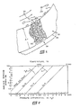
- FIGURE 2 A chart relating surface tension, pore diameter, temperature, and pressure differential for water and potassium as heat transfer fluids is provided in FIGURE 2.
- the pressure differential that can be sustained by the surface tension in the liquid meniscus at the inlet to a pore filled with liquid is directly proportional to the surface tension and inversely proportional to the pore diameter.
- the surface tension varies from one liquid to another, and, for any given liquid, it varies with temperature.
- FIGURE 2 shows the relations between the parameters to facilitate the estimation of the maximum pressure differential or Apmax for a typical range of pore sizes and for the normal operating temperature range of each of the heat transfer fluids illustrated.
- the liquid is chosen and the operating temperature desired to determine the surface tension is selected.
- the ⁇ pmax can be found for the pore size chosen. That is, enter the chart of FIGURE 2 on the top horizontal scale at the desired temperature in degrees Rankine, go vertically downward to the curve for the liquid chosen, and read the surface tension in dynes/cm from the scale at the left. Then, move to the right or left for that surface tension to the pore size defined by the system of slanting parallel lines, and read the pressure differential sustainable in inches of water on the bottom scale.
- FIGURE 13d shows the menisci 32 at the ⁇ pmax
- FIGURE 13b shows the menisci 32 at about 1/2 Apmax, which is a preferred operating point
- FIGURE 13c shows the menisci 32 at about 3i4 ⁇ pmax and in FIGURE 13a the menisci are at about 1/4 Apmax, and it is preferred that the P be maintained in this range.
- the pore size that will develop the desired menisci configuration under the particular conditions can be selected from FIGURE 2.
- the surface pore may be larger (or smaller) than the idealized pore.
- the proper (or chosen) pore size must exist at some point in any large channel through the porous material. If a smaller pore size exists, that channel's pressure drop will be higher. Since, under any given set of operating conditions, the pressure gradient is fixed, this channel will tend to penalize permeability, so smaller pores are undesirable. If a larger pore completely penetrates the material, vapor breakthrough will occur at a pressure gradient that has been chosen based on nominal pore size.
- Another factor involved in the selection of the material for the porous medium 20 is the surface area required to remove liquid droplets contacting and wetting the pores adjacent to the surface 24. Assuming that 100 percent of the liquid contacting the surface 24 wets the pores adjacent to the surface, the surface area needed may be calculated by dividing the entrained liquid mass flow rate by the permeability of the material. Table IV shows of Table III, assuming a pressure differential of 50% of Apmax.
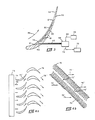
- FIGURE 3 illustrates use of a porous medium 50 to remove liquid from a stator blade 52 located in the turbine portion of a Rankine cycle electric generating system which is a particularly advantageous embodiment of the present invention for achieving both droplet separation and removal of accumulated moisture from the blades.
- turbine bucket erosion is not caused by the impact of microscopic droplets that condense from the vapor in the course of its expansion it passes through the turbine. Instead, such erosion is caused by large diameter droplets which coalesce from moisture accumulating on the stator blades and which dribble from the trailing edge of the stator blades into the path of the fast moving rotor blades.
- These large diameter secondary droplets can range in size from 50 to several hundred microns.
- the porous medium 50 is in the nature of an insert provided on the concave surface 54 although the insert may be provided on both the concave and convex surfaces.
- the medium 50 may be secured at its ends using electron beam welds 57.
- the shape of the medium 50 conforms to the shape of the surface 54 so that a predefined vapor flow path indicated by the direction of arrow 59 adjacent to the surface 54 is not significantly altered.
- Liquid moving out of the inner surface 60 is collected in axial channels 61 which are interconnected to provide flow passages to an outlet point illustrated schematically at 62.
- liquid can be drained by gravity using a siphoning technique or by other suitable means.
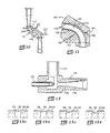
- removal of collected liquid from the stator blade 52 may be accomplished as illustrated schematically in FIGURE 3 using a conduit 63 which is connected between outlet 62 and a pump unit 64 configured to induce fluid movement through the insert 50 by creating a pressure differential DP as described above with reference to FIGURE 1.
- Pump unit 64 preferably is provided by a jet pump, particularly in zero gravity conditions, and one form of a suitably configured pump is illustrated in FIGURE 12 to be discussed subsequently.
- Power for the pump unit 64 is indicated at 66 and may, in the case of a jet pump, be provided using the output of the boiler feed pump in a potassium Rankine cycle system and conducted to the pump unit 64 through conduit 68.
- the outlet of the unit 64 may be recirculated to the system boiler, indicated schematically at 70, by means of conduit 72.
- this embodiment enables significant reduction in rotor blade erosion problems without a significant concomitant power loss (pressure drop) such as may exist with other separation schemes.
- the embodiment is expected to provide a significant power gain because the avoidance of dribble from the stator reduces the drag force experienced by the rotors as a result of the entrained liquid.
- porous medium inserts at the boiler outlet in the form of a series of successive airfoil-type members or flow diverters constructed similarly to the stator blade and designed to divert the flow sufficiently to achieve the necessary trans verse droplet movement while providing substantially unobstructed passageways for minimizing flow separation and pressure drop.
- Each individual path of the flow through successive pairs of diverters constitutes a conduit defining successive bends for smoothly changing the direction of the gas stream moving therethrough so as to avoid conditions which may give rise to flow separation and any attendant turbulence and pressure drop occasioned thereby.
- the radii of curvature of successive bends within the conduit lie generally within a plane and generally on opposite sides of the flow path as viewed perpendicular to the plane so as to cause generally oppositely directed successive changes in direction of the vapor for encouraging transverse movement of the droplets relative to the local gas flow direction, and toward and into contact with the walls of the divertors by centrifugal force.
- FIGURE 4a One means of accomplishing this is illustrated in FIGURE 4a where a first row of divertors in the general shape of airfoil blades 74 directs the vaporliquid stream from a boiler unit indicated schematically at 73 along a curvilinear flow path representing a change in flow direction of approximately 45 . which is the approximate difference in direction between flow direction arrows 75' and 75 .
- Airfoil blades 76 arranged in a second row are immediately downstream of the first row of airfoil blades 74, and are oriented with respect to one another and to blades 74 to direct the vapor-liquid stream through a change in direction of approximately 90 . as indicated by the difference in direction between flow direction arrows 75" and 75'. Additional rows of airfoils may be used.
- the surfaces of the airfoils 74 and 76 facing the flow are provided with porous medium inserts generally as shown in FIGURE 3 to remove moisture contacting and wetting the concave and convex surfaces.
- the first and second rows of airfoils 74 and 76 may also be arranged to provide two 90° changes in direction by disposing the first row 74 at an approximately 45 . angle with respect to the approach ing flow as indicated by arrows 75 . Consequently, flow direction arrows 75 are at about a 90° angle with respect to flow direction arrows 75'. Flow exiting the second row 76 proceeds as indicated by the direction of arrows 75 which are substantially perpendicular to flow direction arrows 75 representing the direction of flow movement between rows of blades 74 and 76.
- the turning radius of the bends should be as small as practicable to maximize the centrifugal force, while the turning angle should be as large as practicable to give the droplets sufficient time to move transversely across the streamlines of the vapor stream and contact the porous medium.
- flow separation should be minimized.
- the ratio of the outer radius to the inner radius in the bend is preferably no greater than about 1.5 to reduce the adverse pressure gradient along the inner wall of the bend and thus the tendency toward flow separation and the resulting large scale turbulence.
- the vapor introduced from the boiler unit 73 into the arrangement of porous blades will typically be moving at a velocity that is considerably subsonic, usually in the range of Mach 0.1 to Mach 0.7.
- such velocities are found to yield suprisingly good separation efficiencies of over about 85% for droplets having a size in the range of from about 5 to about 20 um.
- the invention yields separation efficiencies over 95% for droplet diameters over 60 microns with a pressure drop less than about 10% of the inlet dynamic head at velocities below about Mach 0.3, which is therefore a preferred velocity limit for practicing the invention.
- Table 5 shows the separation efficiencies which are achieved through use of a series of successive pairs or banks of airfoils forming a flow conduit as described above with reference to FIGURE 4 and defining two oppositely directed 90° bends as in FIGURE 4b.
- the opposed concave and convex surfaces of the blades were defined by a layer of the Dynapore material described above.
- the data shows a very high overall average separation efficiency of 85% even though the velocities of the vapor moving through the device are relatively low with Mach numbers in the order of 0.06 to 0.15 Mach. Also, it is to be noted that a very low pressure drop was measured through the banks during the tests, ranging from about 0.2 to about 2.7 in. H 2 0. Under these conditions of relatively high separation and relatively low pressure drop, the invention represents an excellent approach for achieving separation of liquid droplets contained in the vapor at a boiler outlet in a power plant context and in the stator blades used in the turbine section as described above.
- FIGURES 5 through 8 illustrate further embodiments of the present invention for removing liquid droplets carried in a vapor stream at the outlet of a boiler in a Rankine steam or potassium vapor cycle.
- a separator section indicated generally at 80 includes apparatus for separating liquid droplets from the vapor stream in accordance with one form of the invention.
- the separator section 80 is placed between duct sections 82 and 84 passing a vapor-liquid stream upward from the outlet of the boiler to the turbine section.
- the separator section 80 includes a downwardly facing cone portion 86 which directs the flow radially outwardly into inlet openings 88 of a plurality of annularly arranged conduits or passageways 90, a portion of which are illustrated in FIGURE 6.
- the passageways are designed to achieve the necessary transverse droplet movement and minimize flow separation and pressure drop through the use of appropriate geometry and substantially unobstructed passageways as described above.
- each passageway 90 contains two approximately 90. bends and has an exit opening 92 axially spaced from, and circumferentially shifted with respect to, the inlet opening 88.
- the passageways 90 are approximately rectangular in cross-section (slightly wider at outer radius), and are lined along their length with a conforming porous medium 94 to remove liquid droplets suspended in the vapor-liquid stream as illustrated and described above with reference to FIGURE 1.
- the medium 94 in each passageway 90 includes an outer surface 96 adjacent to the flow, corresponding to first surface 24 of FIGURE 1, and an inner surface 98 out of which the removed liquid passes, corresponding to second surface 26 of FIGURE 1.
- the medium 94 is supported in a suitable fashion such as the illustrated lands 100 spaced to lu provide a liquid drainage network in spaces 101 adjacent to the inner surface 98, while the lands provide support of the medium 94 to maintain the desired configuration under the dynamic pressure force of the fluid flowing through the passageway 90.
- Liquid movement throughout the medium 94 occurs via capillary action as mentioned above, and movement of the liquid through the medium 94 away from the outer surface 96 in accordance with the invention is preferably accomplished by creating a pressure differential as described above with reference to FIGURE 1.
- a preferred means for creating the pressure differential, particularly under zero gravity conditions, is a jet pump, one form of which is shown in FIGURE 12 to be described subsequently.
- the cone portion 86 of the separator 80 may also be lined on its outer surface with a layer of porous medium 107 as shown in FIGURE 7.
- the vapor-liquid stream flowing radially outward toward the annular arrangement of inlet openings 88 will, because of its changing direction, tend to cause movement of liquid droplets transversely of the flow direction by centrifugal force. A significant portion of these liquid droplets contact and wet the layer of porous medium 107 on the cone 86 and are removed from the medium 107 as described above with reference to FIGURE 1.
- the porous medium 107 may be supported on lands 108 spaced so as to provide a fluid drainage network in gaps 109 between the lands 108 for draining fluid moving through the medium 107.
- FIGURE 8 illustrates interconnection of the spaces 101 adjacent to the medium 94 between the lands 100 to direct removed liquid to a plenum 112 from which it is passed through conduit 114 to the pressure differential producing means.
- FIGURES 9a and 9b illustrate another form of the present invention involving removal of suspended liquid droplets carried in a vapor stream exiting a boiler.
- Each figure is a one-half view of an annular duct arrangement provided at the boiler outlet in much the same manner as the separator section 80 of FIGURE 5.
- FIGURE 9a for example, one-half of a cone-shaped portion 110 is represented and corresponds to the cone-shaped portion 86 of FIGURE 5.
- one half of a cone-shaped portion 111 is shown in FIGURE 9b, also corresponding to cone-shaped portion 86 of FIGURE 5.
- the outer surfaces of the cone portions 110 and 111 preferably are lined with a porous medium in accordance with the invention as described above in FIGURE 7. (The porous medium is omitted from portions 110 and 111 in FIGURES 9a and 9b for clarity.)
- the separator configuration in both FIGURES 9a and 9b is selected to provide two 90. changes in direction for the flow similar to that of the passageways 90 illustrated in FIGURE 6.
- the initial 90 change in direction is radially inwardly of the cone portions 110 and 111 and the flow is not divided. Instead, it is maintained in a continuous annular conduit or channel as it traverses the separator.
- FIGURE 9a illustrates incorporation of porous medium in accordance with the invention in the form of a flat ring 120 adjacent to a first bend 122.
- Ring 120 faces downwardly toward the flow entering the first bend 122, is placed just downstream of the outer radius of the bend, and is maintained in position by suitable means.
- Another section of porous medium in the shape of a band 124 is placed adjacent to a second 90° bend 126 just downstream of the outer radius of the bend, and is supported by suitable means.
- Spaces 128 and 130 are provided behind ring 120 and band 124.
- the spaces 128 and 130 are connected to a jet pump or other suitable device for creating a pressure differential (DP) across the ring 120 and band 124 and collect liquid droplets suspended in the vapor-liquid stream which contact, wet, and are transported through the material of the ring 120 and band 124 in the now familiar manner.
- DP pressure differential
- FIGURE 9b curved annular-shaped porous medium sections 134 and 136 line the passageway.
- Section 136 traverses the outer radius of a first bend 138 and extends along the passageway to the downstream end as the inner radius of the second bend 140.
- Section 134 begins at the downstream end as the inner radius of the first bend 138 and traverses the outer radius of the second bend 140.
- Spaces 142 and 144 behind porous medium sections 134 and 136, respectively, function in the same manner as the spaces 128 and 130 of FIGURE 9a.
- the configuration of FIGURE 9b offers the advantage of more complete coverage of the porous medium along the wall defining the passageway to insure complete removal of liquid droplets contacting the structure directing the flow of fluid through the passageway.
- FIGURES 10 and 11 show another form of the invention wherein the porous medium is inserted into a single duct to separate liquid droplets carried in a flowing vapor-liquid stream.
- a separator section 141 includes a conduit or passageway 145 defining two approximately 90° smooth bends 146 and 147 to achieve transverse droplet movement which minimizes flow separation and pressure drop.
- the passageway 145 is lined with a layer of porous medium 148, preferably provided on both the inner and outer radii of the bends 146 and 147.
- the medium is supported in a suitable fashion, such as the illustrated lands 150 which are spaced apart to define passages 152 which provide a liquid drainage network adjacent the inner surface of the medium 148 between lands 150.
- the spaces 152 are interconnected to drain collected liquid through central conduits 154 and 156 to sumps 158 and 160.
- Sumps 158 and 160 are connected to a jet pump or other suitable means for creating a pressure differential (DP) across the medium 148 to move the fluid through the medium as described above in connection with FIGURE 1. From there, the liquid may be recirculated to the boiler.
- DP pressure differential
- movement of liquid through the thickness of the porous medium of the present invention away from the surface exposed to the vapor stream is preferably accomplished by maintaining a pressure differential (DP) across the medium under the action of gravity or by using a jet pump connected to draw from the space adjacent to the surface of the medium from which the fluid is exiting in the various embodiments of the invention.
- Jet pumps represent a simple liquid scavenging system for use with the invention and, as will be described, are inherently stable to establish a balanced rate of flow through the medium.
- FIGURE 12 One form of a jet pump 168 suitable for use in the invention is illustrated in FIGURE 12.
- liquid from the output of a boiler feed pump is fed into an inlet nozzle 170 of the pump 168 as the driving stream, and it exits through opening 172 at the right-hand end of the nozzle.
- Liquid passing through the porous medium enters inlet conduit 174 at the top of the jet pump 168 as the stream to be driven.
- the high velocity of fluid exiting opening 172 of the nozzle 170 induces a low pressure zone in the throat of a venturi portion 176, drawing liquid through conduit 174 into the venturi.
- the fairly high velocity of the mixed stream is reduced in a venturi diffuser portion 178 to produce an increase in pressure over that of the fluid in conduit 174.
- jet pumps can be used to insure that the surface tension barrier provided at the inlet to the pores 22 by the menisci 32 (See FIGURE 1) will not be broken. This is a result of a subtle, but vital characteristic of jet pumps. It happens that when pumping liquids near their boiling points, a low pressure in the throat of the jet pump venturi 176 can produce cavitation and vapor bubbles that cause a marked loss in the side stream driving pressure and thus the side stream flow rate (and the porous medium DP). By proper design and suitable subcooling of the driving stream, the jet pump can be constructed to tolerate the cavitating regime without difficulty and without cavitation erosion.
- the invention which has been described herein is advantageous in that it does not require high, supersonic flow rates or turbulent flow conditions to achieve an effective separation rate.
- Conventional thinking favors the use of supersonic flow rates or turbulent flow regimes in order to avert particle deposition in undesired locations and for other reasons.
- the present invention involves separation under conditions of laminar flow with subsonic flow velocities below about Mach 0.7 and preferably below about Mach 0.3 to avoid the creation of shock waves or other unstable flow conditions which may give rise to undesirably high pressure losses. Eddies, side currents, etc.
- an overall advantage is that pressure losses are kept to a minimum while separation efficiencies are maintained at a high level. Also, for a given predetermined maximum pressure drop, a higher subsonic velocity can be employed which in turn increases the separation efficiency.
- the invention also uses conventional, easily obtainable equipment and materials, is simple to construct and operate, requires no moving parts, and is readily adaptable for use in a wide variety of applications.
Landscapes
- Chemical & Material Sciences (AREA)
- Chemical Kinetics & Catalysis (AREA)
- Engineering & Computer Science (AREA)
- Mechanical Engineering (AREA)
- General Engineering & Computer Science (AREA)
- Separating Particles In Gases By Inertia (AREA)
- Turbine Rotor Nozzle Sealing (AREA)
Applications Claiming Priority (2)
| Application Number | Priority Date | Filing Date | Title |
|---|---|---|---|
| US377627 | 1989-07-10 | ||
| US07/377,627 US4938785A (en) | 1988-07-22 | 1989-07-10 | Gas-liquid separation |
Publications (1)
| Publication Number | Publication Date |
|---|---|
| EP0408533A1 true EP0408533A1 (fr) | 1991-01-16 |
Family
ID=23489875
Family Applications (1)
| Application Number | Title | Priority Date | Filing Date |
|---|---|---|---|
| EP90850265A Withdrawn EP0408533A1 (fr) | 1989-07-10 | 1990-07-09 | Procédé de séparation des systèmes gaz-liquide |
Country Status (3)
| Country | Link |
|---|---|
| US (1) | US4938785A (fr) |
| EP (1) | EP0408533A1 (fr) |
| JP (1) | JPH03131316A (fr) |
Cited By (4)
| Publication number | Priority date | Publication date | Assignee | Title |
|---|---|---|---|---|
| DE4318385A1 (de) * | 1993-06-03 | 1994-12-08 | Metallgesellschaft Ag | Verfahren und Vorrichtung zum Abscheiden von Schlacketröpfchen aus einem heißen Rohgas aus der Verbrennung oder Vergasung fester oder flüssiger Brennstoffe |
| WO1998015718A1 (fr) * | 1996-10-08 | 1998-04-16 | Siemens Aktiengesellschaft | Turbine a vapeur |
| CN110812892A (zh) * | 2019-11-04 | 2020-02-21 | 江苏华洋新思路能源装备股份有限公司 | 一种化工生产用高效气液分离器 |
| CN111632435A (zh) * | 2020-06-13 | 2020-09-08 | 江苏启景环保技术有限公司 | 一种含液危化品废气净化方法 |
Families Citing this family (19)
| Publication number | Priority date | Publication date | Assignee | Title |
|---|---|---|---|---|
| US5196380A (en) * | 1991-06-06 | 1993-03-23 | Arizona Board Of Reagents | Reactive membrane for filtration and purification of gases of impurities |
| US5637544A (en) * | 1991-06-06 | 1997-06-10 | Arizona Board Of Regents On Behalf Of The University Of Arizona | Reactive membrane for filtration and purification of gases of impurities and method utilizing the same |
| US5677193A (en) * | 1994-06-23 | 1997-10-14 | Lockheed Martin Idaho Technologies Company | Method and apparatus for processing a test sample to concentrate an analyte in the sample from a solvent in the sample |
| DE19504631A1 (de) * | 1995-02-13 | 1996-08-14 | Abb Research Ltd | Leitschaufel für Dampfturbinen |
| KR19990008289A (ko) * | 1995-05-03 | 1999-01-25 | 와이너 길버트 피. | 유체의 여과 및/또는 정화와 관련된 장치 및 방법 |
| US7465692B1 (en) | 2000-03-16 | 2008-12-16 | Pall Corporation | Reactive media, methods of use and assemblies for purifying |
| GB2424454A (en) * | 2005-03-24 | 2006-09-27 | Alstom Technology Ltd | Water extracting turbine stator blade |
| US7875103B2 (en) * | 2006-04-26 | 2011-01-25 | Mueller Environmental Designs, Inc. | Sub-micron viscous impingement particle collection and hydraulic removal system |
| US7846228B1 (en) | 2008-03-10 | 2010-12-07 | Research International, Inc. | Liquid particulate extraction device |
| US8940067B2 (en) | 2011-09-30 | 2015-01-27 | Mueller Environmental Designs, Inc. | Swirl helical elements for a viscous impingement particle collection and hydraulic removal system |
| GB2515464B (en) * | 2013-04-24 | 2021-01-27 | Intelligent Energy Ltd | A water separator |
| US9108144B2 (en) * | 2013-05-21 | 2015-08-18 | Astrium Gmbh | Tank for separating liquid from gas under weightless conditions |
| JP2017072372A (ja) * | 2014-02-19 | 2017-04-13 | 株式会社東芝 | 呼気診断装置 |
| US10272376B2 (en) * | 2014-06-18 | 2019-04-30 | Alupro Oy | Louvered separator |
| NL2019982B1 (en) * | 2017-11-27 | 2019-06-03 | Hadek Protective Systems B V | Wet stack guide vane having a condensate collector |
| JP7179651B2 (ja) * | 2019-02-27 | 2022-11-29 | 三菱重工業株式会社 | タービン静翼、及び蒸気タービン |
| JP7179652B2 (ja) * | 2019-02-27 | 2022-11-29 | 三菱重工業株式会社 | タービン静翼、及び蒸気タービン |
| US11306655B2 (en) | 2019-03-18 | 2022-04-19 | General Electric Company | Turbine engine component and method of cooling |
| US11053814B2 (en) * | 2019-03-18 | 2021-07-06 | General Electric Company | Turbine engine component and method of cooling |
Citations (4)
| Publication number | Priority date | Publication date | Assignee | Title |
|---|---|---|---|---|
| US2857979A (en) * | 1954-06-30 | 1958-10-28 | Shell Dev | Gas-liquid separator with porous wall |
| FR1536189A (fr) * | 1965-08-27 | 1968-08-27 | Exxon Production Research Co | Procédé de séparation des produits constitutifs d'un courant renfermant une prédominance de produits gazeux |
| FR2099389A5 (fr) * | 1970-07-31 | 1972-03-10 | Maschf Augsburg Nuernberg Ag | |
| EP0191553A1 (fr) * | 1985-01-29 | 1986-08-20 | Westinghouse Electric Corporation | Dispositif de protection des conduits de vapeur contre l'érosion par gouttelettes d'eau |
Family Cites Families (18)
| Publication number | Priority date | Publication date | Assignee | Title |
|---|---|---|---|---|
| US1519428A (en) * | 1922-07-01 | 1924-12-16 | Wilisch Julius Alexander | Device for separating solid, liquid, or semigaseous matter from gases, vapors, and the like |
| US3182674A (en) * | 1961-07-24 | 1965-05-11 | Sperry Rand Corp | System and apparatus for producing, maintaining and controlling laminar fluid streamflow |
| US3169038A (en) * | 1962-08-29 | 1965-02-09 | Vac U Max | Filter cleaner for pulverized material conveying system |
| US3353335A (en) * | 1965-10-19 | 1967-11-21 | Edward A Caballcro | Exhaust gas treatment |
| US3403498A (en) * | 1966-11-04 | 1968-10-01 | American Air Filter Co | Method for removing saponifiable and foreign substances from a gas stream |
| US3523408A (en) * | 1968-04-02 | 1970-08-11 | Pall Corp | Gas separator |
| US3528217A (en) * | 1968-05-20 | 1970-09-15 | Exxon Production Research Co | Supersonic flow separator with film flow collector |
| US3528218A (en) * | 1968-05-20 | 1970-09-15 | Exxon Production Research Co | Supersonic flow separator with admixing |
| US3528221A (en) * | 1968-05-20 | 1970-09-15 | Exxon Production Research Co | Triangular supersonic flow separator |
| US3528216A (en) * | 1968-05-20 | 1970-09-15 | Exxon Production Research Co | Jet pump and supersonic flow separator |
| US3559373A (en) * | 1968-05-20 | 1971-02-02 | Exxon Production Research Co | Supersonic flow separator |
| US3650093A (en) * | 1970-01-08 | 1972-03-21 | Pall Corp | Sterile disposable medicament administration system |
| US3828524A (en) * | 1971-08-09 | 1974-08-13 | Nasa | Centrifugal lyophobic separator |
| US4218314A (en) * | 1978-07-20 | 1980-08-19 | Schubert James P | Hyperfiltration scoop apparatus and method |
| US4292050A (en) * | 1979-11-15 | 1981-09-29 | Linhardt & Associates, Inc. | Curved duct separator for removing particulate matter from a carrier gas |
| US4319891A (en) * | 1980-11-13 | 1982-03-16 | Gas Research Institute | Combined sonic agglomerator/cross flow gas filtration system and method |
| US4378976A (en) * | 1981-08-14 | 1983-04-05 | Institute Of Gas Technology | Combined sonic agglomerator/cross flow filtration apparatus and process for solid particle and/or liquid droplet removal from gas streams |
| US4504285A (en) * | 1983-04-15 | 1985-03-12 | Modisette Incorporated | Separation of condensible vapors from gas mixtures |
-
1989
- 1989-07-10 US US07/377,627 patent/US4938785A/en not_active Expired - Lifetime
-
1990
- 1990-07-09 EP EP90850265A patent/EP0408533A1/fr not_active Withdrawn
- 1990-07-10 JP JP2182531A patent/JPH03131316A/ja active Pending
Patent Citations (4)
| Publication number | Priority date | Publication date | Assignee | Title |
|---|---|---|---|---|
| US2857979A (en) * | 1954-06-30 | 1958-10-28 | Shell Dev | Gas-liquid separator with porous wall |
| FR1536189A (fr) * | 1965-08-27 | 1968-08-27 | Exxon Production Research Co | Procédé de séparation des produits constitutifs d'un courant renfermant une prédominance de produits gazeux |
| FR2099389A5 (fr) * | 1970-07-31 | 1972-03-10 | Maschf Augsburg Nuernberg Ag | |
| EP0191553A1 (fr) * | 1985-01-29 | 1986-08-20 | Westinghouse Electric Corporation | Dispositif de protection des conduits de vapeur contre l'érosion par gouttelettes d'eau |
Non-Patent Citations (1)
| Title |
|---|
| PATENT ABSTRACTS OF JAPAN vol. 8, no. 16 (M-270)(1453) 24 January 1984, & JP-A-58 176404 (MITSUBISHI JUKOGYO K.K.) 15 October 1983, * |
Cited By (4)
| Publication number | Priority date | Publication date | Assignee | Title |
|---|---|---|---|---|
| DE4318385A1 (de) * | 1993-06-03 | 1994-12-08 | Metallgesellschaft Ag | Verfahren und Vorrichtung zum Abscheiden von Schlacketröpfchen aus einem heißen Rohgas aus der Verbrennung oder Vergasung fester oder flüssiger Brennstoffe |
| WO1998015718A1 (fr) * | 1996-10-08 | 1998-04-16 | Siemens Aktiengesellschaft | Turbine a vapeur |
| CN110812892A (zh) * | 2019-11-04 | 2020-02-21 | 江苏华洋新思路能源装备股份有限公司 | 一种化工生产用高效气液分离器 |
| CN111632435A (zh) * | 2020-06-13 | 2020-09-08 | 江苏启景环保技术有限公司 | 一种含液危化品废气净化方法 |
Also Published As
| Publication number | Publication date |
|---|---|
| US4938785A (en) | 1990-07-03 |
| JPH03131316A (ja) | 1991-06-04 |
Similar Documents
| Publication | Publication Date | Title |
|---|---|---|
| US4938785A (en) | Gas-liquid separation | |
| US5314529A (en) | Entrained droplet separator | |
| EP0068792B1 (fr) | Agencement multiple de cyclones pour fluides | |
| JP3323781B2 (ja) | ガス移送配管 | |
| US4278550A (en) | Fluid separator | |
| US9764265B2 (en) | Swirl helical elements for a viscous impingement particle collection and hydraulic removal system | |
| US9101869B2 (en) | Swirl helical elements for a viscous impingement particle collection and hydraulic removal system | |
| EP0022852B1 (fr) | Separateur a tourbillon divergent | |
| CA1300043C (fr) | Separateur de particules liquides constitue de parois a ailettes | |
| JP2015511872A (ja) | 改善された燃料電池電解質の再生器および分離器 | |
| EP0104248B1 (fr) | Generateur compact de courant a circulation d'air humide | |
| CN110835565B (zh) | 一种天然气气液分离装置 | |
| EP2463008A1 (fr) | Séparateur permettant de séparer un écoulement de fluide de gaz avec une phase dispersée | |
| JPH0248630B2 (fr) | ||
| JPH07269800A (ja) | 配管装置 | |
| WO2002100515A2 (fr) | Systeme de separation de composant liquide immiscible entraine dans un courant de gaz humide | |
| BG98095A (bg) | Устройство за разделяне на многокомпонентни флуиди | |
| US3881900A (en) | Gas liquid separator | |
| US3507099A (en) | Centrifugal liquid-vapor separator | |
| US11305296B2 (en) | Multiphase fluid dispenser | |
| JP2003114293A (ja) | 気水分離器及び沸騰水型原子炉 | |
| Zeng et al. | Experimental study on two different gas-liquid separators under different flow patterns | |
| US8673039B2 (en) | Enhanced vane bundle design | |
| US4892140A (en) | Condenser vent siphon line | |
| CN107188270A (zh) | 一种油水混合物的外起旋分离装置 |
Legal Events
| Date | Code | Title | Description |
|---|---|---|---|
| PUAI | Public reference made under article 153(3) epc to a published international application that has entered the european phase |
Free format text: ORIGINAL CODE: 0009012 |
|
| AK | Designated contracting states |
Kind code of ref document: A1 Designated state(s): AT BE CH DE DK ES FR GB GR IT LI LU NL SE |
|
| 17P | Request for examination filed |
Effective date: 19910716 |
|
| 17Q | First examination report despatched |
Effective date: 19930415 |
|
| STAA | Information on the status of an ep patent application or granted ep patent |
Free format text: STATUS: THE APPLICATION HAS BEEN WITHDRAWN |
|
| 18W | Application withdrawn |
Withdrawal date: 19930715 |