EP0408022B1 - Device for locking a blood centrifugation cell on a chuck - Google Patents
Device for locking a blood centrifugation cell on a chuck Download PDFInfo
- Publication number
- EP0408022B1 EP0408022B1 EP90113308A EP90113308A EP0408022B1 EP 0408022 B1 EP0408022 B1 EP 0408022B1 EP 90113308 A EP90113308 A EP 90113308A EP 90113308 A EP90113308 A EP 90113308A EP 0408022 B1 EP0408022 B1 EP 0408022B1
- Authority
- EP
- European Patent Office
- Prior art keywords
- plate
- locking
- ring
- cell
- base
- Prior art date
- Legal status (The legal status is an assumption and is not a legal conclusion. Google has not performed a legal analysis and makes no representation as to the accuracy of the status listed.)
- Expired - Lifetime
Links
Images


Classifications
-
- B—PERFORMING OPERATIONS; TRANSPORTING
- B04—CENTRIFUGAL APPARATUS OR MACHINES FOR CARRYING-OUT PHYSICAL OR CHEMICAL PROCESSES
- B04B—CENTRIFUGES
- B04B7/00—Elements of centrifuges
-
- B—PERFORMING OPERATIONS; TRANSPORTING
- B04—CENTRIFUGAL APPARATUS OR MACHINES FOR CARRYING-OUT PHYSICAL OR CHEMICAL PROCESSES
- B04B—CENTRIFUGES
- B04B9/00—Drives specially designed for centrifuges; Arrangement or disposition of transmission gearing; Suspending or balancing rotary bowls
- B04B9/08—Arrangement or disposition of transmission gearing ; Couplings; Brakes
-
- Y—GENERAL TAGGING OF NEW TECHNOLOGICAL DEVELOPMENTS; GENERAL TAGGING OF CROSS-SECTIONAL TECHNOLOGIES SPANNING OVER SEVERAL SECTIONS OF THE IPC; TECHNICAL SUBJECTS COVERED BY FORMER USPC CROSS-REFERENCE ART COLLECTIONS [XRACs] AND DIGESTS
- Y10—TECHNICAL SUBJECTS COVERED BY FORMER USPC
- Y10T—TECHNICAL SUBJECTS COVERED BY FORMER US CLASSIFICATION
- Y10T279/00—Chucks or sockets
- Y10T279/24—Chucks or sockets by centrifugal force
-
- Y—GENERAL TAGGING OF NEW TECHNOLOGICAL DEVELOPMENTS; GENERAL TAGGING OF CROSS-SECTIONAL TECHNOLOGIES SPANNING OVER SEVERAL SECTIONS OF THE IPC; TECHNICAL SUBJECTS COVERED BY FORMER USPC CROSS-REFERENCE ART COLLECTIONS [XRACs] AND DIGESTS
- Y10—TECHNICAL SUBJECTS COVERED BY FORMER USPC
- Y10T—TECHNICAL SUBJECTS COVERED BY FORMER US CLASSIFICATION
- Y10T279/00—Chucks or sockets
- Y10T279/26—Chucks or sockets with centering means
-
- Y—GENERAL TAGGING OF NEW TECHNOLOGICAL DEVELOPMENTS; GENERAL TAGGING OF CROSS-SECTIONAL TECHNOLOGIES SPANNING OVER SEVERAL SECTIONS OF THE IPC; TECHNICAL SUBJECTS COVERED BY FORMER USPC CROSS-REFERENCE ART COLLECTIONS [XRACs] AND DIGESTS
- Y10—TECHNICAL SUBJECTS COVERED BY FORMER USPC
- Y10T—TECHNICAL SUBJECTS COVERED BY FORMER US CLASSIFICATION
- Y10T403/00—Joints and connections
- Y10T403/59—Manually releaseable latch type
- Y10T403/598—Transversely sliding pin
-
- Y—GENERAL TAGGING OF NEW TECHNOLOGICAL DEVELOPMENTS; GENERAL TAGGING OF CROSS-SECTIONAL TECHNOLOGIES SPANNING OVER SEVERAL SECTIONS OF THE IPC; TECHNICAL SUBJECTS COVERED BY FORMER USPC CROSS-REFERENCE ART COLLECTIONS [XRACs] AND DIGESTS
- Y10—TECHNICAL SUBJECTS COVERED BY FORMER USPC
- Y10T—TECHNICAL SUBJECTS COVERED BY FORMER US CLASSIFICATION
- Y10T403/00—Joints and connections
- Y10T403/60—Biased catch or latch
- Y10T403/602—Biased catch or latch by separate spring
- Y10T403/604—Radially sliding catch
Definitions
- the invention relates to a device for locking a blood centrifugation cell on a rotatable chuck.
- the centrifugation of blood results in the separation of various weight fraction components such as plasma, red cells, platelets and white cells within centrifugation cells.
- the centrifugation cells include a stationary coupling to which ducts are connected for the inflow of the blood and for the outflow of the separated fraction to be extracted.
- the base of the cell In order to rotate the centrifugation cell, the base of the cell is locked on a chuck connected to a rotatable shaft.
- the locking mechanisms of the prior art do not always adequately secure the cell to the chuck and usually require special tools which can be difficult and time consuming to actuate.
- Typical prior art locking mechanisms include various jaws and ring segments which retain several points of the base of the cell to the chuck, but such locking elements are difficult to put in place and do not ensure absolute safety in the locking of the cell.
- US-A-1 385 306 discloses a spinning box for artificial silk comprising a cylindrical base and means for securing the base to a spinning spindle.
- An offset flange is provided at the lower edge of the base, and housings are formed in a radial and slightly downward direction in the base.
- Sliding locking pins are housed in the housings and such pins are biased outwardly by springs also housed in the housings.
- the locking pins are provided with beveled noses which protrude outside the periphery of the cylindrical base, due to the biasing of the locking pins outwardly by the springs.
- the spinning box further comprises a basket like cover provided adjacent its lower margin with a V-shaped annulus.
- the beveled noses of the locking pins bear against the lower side of the V-shaped annulus of the cover thereby to retain the cover on the base and in particular to retain the cover in contact with the offset flange thereof.
- the springs serve to ensure the initial engagement of the locking pins with the annulus in the cover, and the pressure exerted by centrifugal force during the rotation of the box exceeds the pressure of the springs and assures the firm engagement of the cover on the base.
- An object of the present invention is to provide a device for safely and securely locking a blood centrifugation cell on a chuck easily and quickly by an operator without requiring the use of any tool.
- the invention provides a device for locking the base of a blood centrifugation cell on a rotatable generally disc-shaped chuck plate.
- the chuck plate encloses a plurality of elastic locators which extend radially a slight distance from the periphery of the plate.
- the plate further encloses a plurality of locking means which are biased inwardly toward the center of the plate at rest and which are radially moved outwardly away from the center of the plate by centrifugal force to extend beyond the periphery of the plate during rotation of such plate.
- An annular locking ring engages the base of the cell and extends around the periphery of the chuck plate.
- the locking ring has a plurality of internal recesses for initially receiving the elastic locators, and the locking means during centrifugation to secure the cell to the chuck plate.
- a chuck plate 1 on which a blood centrifugation cell 2 is shown secured by an annular locking ring 3 of the present invention includes an annular inward flange 3a which is adapted to engage a corresponding annular outward flange at the base of the cell, and which includes a cylindrical portion which is adapted to extend beyond the periphery of the chuck plate 1.
- the cell and locking ring are initially positioned to the chuck plate by means of elastic locators, and are rigidly secured during rotation by locking elements within the plate which engage the ring by centrifugal force.
- the locking elements are particularly illustrated in figures 1 and 2.
- the chuck plate 1 includes three radial bore holes 4, 5 and 6, which are each threaded to receive a generally cylindrical sleeve 7 which encloses a slidable pin 8 having a base 8a.
- the sleeve is counterbored to retain a compression spring 9 between the sleeve and the pin base 8a, so that the pin is normally biased radially inwardly within the chuck plate.
- the locking ring 3 has three openings shown as slots 10, 11 and 12 aligned with the heads of the pins 8. The openings could similarly be precise circular apertures or internal recesses within the ring but are preferable slots.
- the spring 9 retains the pin 8 within the plate (as shown in figure 1).
- centrifugal force is generated on the pins 8 and overcomes the bias action of the springs, pushing the pins radially outward so that each pin engages the corresponding slot 10, 11 and 12 of the locking ring to securely lock the cell 2 to the chuck plate.
- the angular velocity of the chuck plate decreases and the spring 9 is then adequate to retract the pins radially inwardly within the chuck plate.
- the blood centrifugation cell 2 and the locking ring 3 are initially positioned on the chuck plate 1 by elastic locators shown in figures 1 and 2.
- the elastic locators are positioned contiguous with the locking elements in bore holes 13, 14 and 15 in the chuck plate 1.
- An example of an elastic locator is a small cylinder 16 which retains a spherical ball 17 which is biased outwardly by compression spring 18.
- the cylinders 16 are retained in the plate by suitable thread engagement into corresponding threads in the bore holes 13, 14 and 15, so that the ball extends a slight distance from the periphery of the chuck plate.
- the lower end of the ring compresses the balls 17 against the springs 18 within the plate.
- the springs force the balls 17 into the slots with a "perceptible snap" to properly align and initially secure the cell and ring onto the chuck plate.
- the elastic locators could engage discrete apertures or recesses in the locking ring, however since the elastic locators and the locking elements are contiguous, the use of the common slots 10, 11 and 12 are convenient and assure that the ring is properly aligned to receive the locking elements during centrifugation.
- the plate 1 and locking ring 3 are also provided with upper and lower rigid locators to radially orient the ring relative to the plate to insure the engagement of the elastic locators and the locking elements into the respective slots.
- the upper rigid locators comprise three screws 26 inserted in threaded holes 19, 20 and 21 provided on the upper face of the chuck plate 1.
- the holes are arranged in such a position as to allow the heads of the screws to protrude from the periphery of the plate by an amount suitable to slidably engage longitudinal grooves 22, 23 and 24 provided in the ring.
- the lower rigid locators comprise three tabs 27 which are fixed by means of screws in holes such as 25 and which protrude from the periphery of the plate by an amount adapted to engage a notch (24a shown in figure 6) provided at the base of each of the grooves 22, 23, 24.
- the tabs 27 and the respective notch provide a clear visual reference for the operator while positioning the locking ring on the plate.
- Figure 7 illustrates a further embodiment of the locking element and of the elastic locator, which instead of being constituted by separate elements as in the first described embodiment are combined into a single device.
- a cylindrical sleeve 28 is associated with a radial hole of the plate 1 and slidably contains a pin 29 which has a slightly extended rounded head and is provided with a foot 29a on which compression springs 30 and 31 act on opposite sides.
- the springs are dimensioned so that their balanced action allows the pin 29 to perform as the elastic locator to initially position the cell and ring, and to further extend outwardly during centrifugation to perform as the locking element within the corresponding opening in the locking ring.
- the invention thus allows the cell to be positioned and locked on the chuck in an extremely rapid and easy manner, without the aid of any tool.
- the operator simply places the cell on the chuck plate, then positions the locking ring over the cell and the plate following the indications provided by the fixed locators until the elastic locators snap into the slots, and then the action of the centrifugal force automatically provides the locking of the cell to the plate.
- the ring may be associated with the cell in any manner, by gluing, welding, mechanical coupling or by being monolithic with the cell itself.
- the locking and locator elements can furthermore be provided in a different manner and can be arranged with respect to one another differently from the described manner, so long as they are always evenly distributed along the circumference of the plate for obvious reasons of dynamic balancing.
Abstract
Description
- The invention relates to a device for locking a blood centrifugation cell on a rotatable chuck.
- The centrifugation of blood results in the separation of various weight fraction components such as plasma, red cells, platelets and white cells within centrifugation cells. The centrifugation cells include a stationary coupling to which ducts are connected for the inflow of the blood and for the outflow of the separated fraction to be extracted. In order to rotate the centrifugation cell, the base of the cell is locked on a chuck connected to a rotatable shaft. The locking mechanisms of the prior art do not always adequately secure the cell to the chuck and usually require special tools which can be difficult and time consuming to actuate. Typical prior art locking mechanisms include various jaws and ring segments which retain several points of the base of the cell to the chuck, but such locking elements are difficult to put in place and do not ensure absolute safety in the locking of the cell.
- US-A-1 385 306 discloses a spinning box for artificial silk comprising a cylindrical base and means for securing the base to a spinning spindle. An offset flange is provided at the lower edge of the base, and housings are formed in a radial and slightly downward direction in the base. Sliding locking pins are housed in the housings and such pins are biased outwardly by springs also housed in the housings. The locking pins are provided with beveled noses which protrude outside the periphery of the cylindrical base, due to the biasing of the locking pins outwardly by the springs. The spinning box further comprises a basket like cover provided adjacent its lower margin with a V-shaped annulus. The beveled noses of the locking pins bear against the lower side of the V-shaped annulus of the cover thereby to retain the cover on the base and in particular to retain the cover in contact with the offset flange thereof. The springs serve to ensure the initial engagement of the locking pins with the annulus in the cover, and the pressure exerted by centrifugal force during the rotation of the box exceeds the pressure of the springs and assures the firm engagement of the cover on the base.
- An object of the present invention is to provide a device for safely and securely locking a blood centrifugation cell on a chuck easily and quickly by an operator without requiring the use of any tool.
- The invention provides a device for locking the base of a blood centrifugation cell on a rotatable generally disc-shaped chuck plate. The chuck plate encloses a plurality of elastic locators which extend radially a slight distance from the periphery of the plate. The plate further encloses a plurality of locking means which are biased inwardly toward the center of the plate at rest and which are radially moved outwardly away from the center of the plate by centrifugal force to extend beyond the periphery of the plate during rotation of such plate. An annular locking ring engages the base of the cell and extends around the periphery of the chuck plate. The locking ring has a plurality of internal recesses for initially receiving the elastic locators, and the locking means during centrifugation to secure the cell to the chuck plate.
- Further characteristics and advantages will become apparent from the description of preferred but not exclusive embodiments of the invention, illustrated only by way of non-limitative example in the accompanying drawings, wherein:
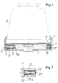
- Figure 1 is a sectional view of the invention, taken along the plane I-I of figure 2, with the cell indicated in broken lines, and with assembled locking and elastic locator elements;
- Figure 2 is a plan view of the chuck plate;
- Figure 3 is a partially sectional side view of the chuck plate, taken along the plane III-III of figure 2;
- Figure 4 is a partial lower side perspective view of a detail of the chuck plate illustrating one of the rigid locators;
- Figure 5 is a sectional plan view of the locking ring, taken along the plane V-V of figure 6;
- Figure 6 is a sectional side view of the locking ring, taken along the plane VI-VI of figure 5;
- Figure 7 is a partial sectional view similar to figure 1 illustrating a further embodiment of a combined locking and elastic locator element.
- With reference to the above figures, a
chuck plate 1 on which ablood centrifugation cell 2 is shown secured by anannular locking ring 3 of the present invention. Thelocking ring 3 includes an annular inward flange 3a which is adapted to engage a corresponding annular outward flange at the base of the cell, and which includes a cylindrical portion which is adapted to extend beyond the periphery of thechuck plate 1. The cell and locking ring are initially positioned to the chuck plate by means of elastic locators, and are rigidly secured during rotation by locking elements within the plate which engage the ring by centrifugal force. - The locking elements are particularly illustrated in figures 1 and 2. The
chuck plate 1 includes threeradial bore holes cylindrical sleeve 7 which encloses aslidable pin 8 having a base 8a. The sleeve is counterbored to retain acompression spring 9 between the sleeve and the pin base 8a, so that the pin is normally biased radially inwardly within the chuck plate. Thelocking ring 3 has three openings shown asslots pins 8. The openings could similarly be precise circular apertures or internal recesses within the ring but are preferable slots. - When the
chuck plate 1 is at rest, thespring 9 retains thepin 8 within the plate (as shown in figure 1). When the plate is rotated, centrifugal force is generated on thepins 8 and overcomes the bias action of the springs, pushing the pins radially outward so that each pin engages thecorresponding slot cell 2 to the chuck plate. Upon completion of the centrifugal rotation, the angular velocity of the chuck plate decreases and thespring 9 is then adequate to retract the pins radially inwardly within the chuck plate. - As previously discussed, the
blood centrifugation cell 2 and thelocking ring 3 are initially positioned on thechuck plate 1 by elastic locators shown in figures 1 and 2. The elastic locators are positioned contiguous with the locking elements inbore holes chuck plate 1. An example of an elastic locator is asmall cylinder 16 which retains aspherical ball 17 which is biased outwardly bycompression spring 18. Thecylinders 16 are retained in the plate by suitable thread engagement into corresponding threads in thebore holes - When the
locking ring 3 is slid over the periphery of the chuck plate, the lower end of the ring (aided by an internal annular bevel) compresses theballs 17 against thesprings 18 within the plate. When theslots balls 17 into the slots with a "perceptible snap" to properly align and initially secure the cell and ring onto the chuck plate. The elastic locators could engage discrete apertures or recesses in the locking ring, however since the elastic locators and the locking elements are contiguous, the use of thecommon slots - As shown particularly in figures 3-6, the
plate 1 andlocking ring 3 are also provided with upper and lower rigid locators to radially orient the ring relative to the plate to insure the engagement of the elastic locators and the locking elements into the respective slots. - The upper rigid locators comprise three
screws 26 inserted in threadedholes chuck plate 1. The holes are arranged in such a position as to allow the heads of the screws to protrude from the periphery of the plate by an amount suitable to slidably engagelongitudinal grooves tabs 27 which are fixed by means of screws in holes such as 25 and which protrude from the periphery of the plate by an amount adapted to engage a notch (24a shown in figure 6) provided at the base of each of thegrooves tabs 27 and the respective notch provide a clear visual reference for the operator while positioning the locking ring on the plate. - Figure 7 illustrates a further embodiment of the locking element and of the elastic locator, which instead of being constituted by separate elements as in the first described embodiment are combined into a single device. A
cylindrical sleeve 28 is associated with a radial hole of theplate 1 and slidably contains apin 29 which has a slightly extended rounded head and is provided with a foot 29a on which compression springs 30 and 31 act on opposite sides. The springs are dimensioned so that their balanced action allows thepin 29 to perform as the elastic locator to initially position the cell and ring, and to further extend outwardly during centrifugation to perform as the locking element within the corresponding opening in the locking ring. - From what has been described, the invention thus allows the cell to be positioned and locked on the chuck in an extremely rapid and easy manner, without the aid of any tool. The operator simply places the cell on the chuck plate, then positions the locking ring over the cell and the plate following the indications provided by the fixed locators until the elastic locators snap into the slots, and then the action of the centrifugal force automatically provides the locking of the cell to the plate.
- The described invention is susceptible to numerous modifications and variations, all of which are within the scope of the inventive concept; thus, for example, the ring may be associated with the cell in any manner, by gluing, welding, mechanical coupling or by being monolithic with the cell itself.
- The locking and locator elements can furthermore be provided in a different manner and can be arranged with respect to one another differently from the described manner, so long as they are always evenly distributed along the circumference of the plate for obvious reasons of dynamic balancing.
- Where technical features mentioned in any claim are followed by reference signs, those reference signs have been included for the sole purpose of increasing the intelligibility of the claims and accordingly such reference signs do not have any limiting effect on the scope of each element identified by way of example by such reference signs.
Claims (11)
- A device for locking the base of a blood centrifugation cell (2) on a rotatable disc-shaped chuck plate (1) comprising:
a plurality of locking means (8;29) enclosed within the chuck plate (1) which are biased inwardly toward the center of the plate at rest and which are radially expandable by centrifugal force to move outwardly away from the center of the plate and extend beyond the periphery of the plate during rotation;
an annular locking ring (3) for engaging the base of the cell and for extending around the periphery of said base plate;
said locking ring having a plurality of first recesses (10-12) for receiving said locking means during rotation. - The device according to claim 1, characterized in that said cell (2) includes an annular flange extending outwardly from the base thereof; and said ring (3) is removably associated with the cell and is provided with an annular inward flange (3a) for engaging the flange of said cell.
- The device according to claim 1, characterized in that said ring (3) is monolithically associated with the cell (2).
- The device according to claim 1, characterized in that it comprises a plurality of compressible elastic locators (17) enclosed within the chuck plate which are biased to extend radially a slight distance from the periphery of the plate; and said locking ring further including a plurality of second recesses (10-12) for receiving said elastic locators.
- The device according to claim 1, characterized in that said plate (1) includes a plurality of first radial bore holes (4-6) in the periphery thereof and said locking means comprises:
a cylindrical sleeve (7) enclosed within each of said bore holes;
a pin (8) having a base (8a) thereon and which is slidably retained within each of said sleeves;
a spring (9) retained between each said base and said sleeve. - The device according to claim 4, characterized in that said plate further includes a plurality of second radial bore holes (13-15) and said elastic locators comprise a spherical ball (17) and a compression spring (18) retained within each of said second bore holes so that said balls are compressible within said plate by said locking ring and which are extendable to engage said second recesses (10-12) in said ring.
- The device according to claim 4, characterized in that said plate includes a plurality of first bore holes (4-6) and a plurality of second bore holes (13-15);
said locking means comprises a cylindrical sleeve (7) within each of said first bore holes; a pin (8) having a base (8a) thereon and which is slidably retained within each of said sleeves; and a spring (9) retained between each said base and said sleeve so that said pins engage said first recesses in said locking ring during rotation;
and characterized in that said elastic locators comprise a spherical ball (17) and a compression spring (18) retained within each of said second bore holes so that said balls are compressible within said plate by said locking ring and which are extendable to engage said second recesses in said ring to retain the cell and the ring at rest. - The device according to claim 7, characterized in that said plate (1) includes three said first bore holes and three contiguous second bore holes, and said first recesses and said second recesses in said locking ring are arranged as three lateral slots (10-12).
- The device according to claim 4 characterized in that said plate (1) further includes at least one fixed radial locator (26,27) which extends a slight distance from the periphery of said plate, and said ring includes at least one longitudinal grooved recess (22-24) for slidably receiving and retaining said radial locator so that said first and said second recesses are respectively aligned for engagement with said locking means and said elastic locators.
- A device according to claim 1, characterized in that said locking means (29) is further elastically biased so that at rest said locking means is extended a slight distance from the periphery of said plate (1) so that said locking means is compressible within said plate by said locking ring (3) and is extendable into said recess (10-12) to initially secure said cell and said ring onto said plate; and is further extendable and non-compressible during rotation.
- The device according to claim 10, characterized in that said plate includes a plurality of radial bore holes in the periphery thereof and said locking means comprises:
a cylindrical sleeve (28) enclosed within each of said bore holes;
a pin (29) having a head and a foot (29a) and which is slidably retained within each of said sleeves;
a first spring (30) positioned between each said sleeve and the base of said bore hole to elastically extend said pin a slight distance beyond the periphery of said plate; and
a second spring (31) positioned between each said foot and said sleeve to retract said pin to the desired position when the plate is not rotating.
Applications Claiming Priority (2)
| Application Number | Priority Date | Filing Date | Title |
|---|---|---|---|
| IT2119589 | 1989-07-14 | ||
| IT8921195A IT1230356B (en) | 1989-07-14 | 1989-07-14 | BLOCK SPINDLE BLOCKING DEVICE FOR BLOOD CENTRIFUGATION. |
Publications (3)
| Publication Number | Publication Date |
|---|---|
| EP0408022A2 EP0408022A2 (en) | 1991-01-16 |
| EP0408022A3 EP0408022A3 (en) | 1991-10-30 |
| EP0408022B1 true EP0408022B1 (en) | 1995-02-15 |
Family
ID=11178205
Family Applications (1)
| Application Number | Title | Priority Date | Filing Date |
|---|---|---|---|
| EP90113308A Expired - Lifetime EP0408022B1 (en) | 1989-07-14 | 1990-07-12 | Device for locking a blood centrifugation cell on a chuck |
Country Status (10)
| Country | Link |
|---|---|
| US (1) | US5062826A (en) |
| EP (1) | EP0408022B1 (en) |
| JP (1) | JPH0738955B2 (en) |
| AT (1) | ATE118372T1 (en) |
| AU (1) | AU619994B2 (en) |
| CA (1) | CA2021065C (en) |
| DE (2) | DE9010409U1 (en) |
| DK (1) | DK0408022T3 (en) |
| ES (1) | ES2068288T3 (en) |
| IT (1) | IT1230356B (en) |
Families Citing this family (16)
| Publication number | Priority date | Publication date | Assignee | Title |
|---|---|---|---|---|
| EP0568191B1 (en) * | 1992-04-29 | 1997-05-28 | Cobe Laboratories, Inc. | Centrifuge having a single swing arm for retaining a stator tube |
| US5308309A (en) * | 1992-12-23 | 1994-05-03 | Therakos, Inc. | Securing system for centrifuge chamber |
| BE1007431A3 (en) * | 1993-08-04 | 1995-06-13 | Philips Electronics Nv | Food with a lid lock with centrifugal organ. |
| US5591113A (en) * | 1994-10-31 | 1997-01-07 | Cobe Laboratories, Inc. | Centrifugally assisted centrifuge bowl mount |
| US5658231A (en) * | 1995-09-21 | 1997-08-19 | Haemonetics Corporation | Mechanism for securing a separation bowl to a mechanical chuck |
| NZ325024A (en) * | 1995-12-07 | 2000-02-28 | Bristol Myers Squibb Co | centrifuge apparatus with container locking means |
| US5851169A (en) * | 1996-01-31 | 1998-12-22 | Medtronic Electromedics, Inc. | Rotary plate and bowl clamp for blood centrifuge |
| US5964690A (en) * | 1997-03-19 | 1999-10-12 | Medtronic, Inc. | Mechanism for fixing a blood centrifuge bowl to a rotating spindle |
| JP4546794B2 (en) * | 2004-09-15 | 2010-09-15 | トミー工業株式会社 | Centrifuge rotor mounting structure |
| US7998052B2 (en) * | 2006-03-07 | 2011-08-16 | Jacques Chammas | Rotor defining a fluid separation chamber of varying volume |
| US8506825B2 (en) * | 2006-11-27 | 2013-08-13 | Sorin Group Italia S.R.L. | Method and apparatus for controlling the flow rate of washing solution during the washing step in a blood centrifugation bowl |
| EP2138237B1 (en) * | 2008-06-10 | 2011-01-19 | Sorin Group Italia S.r.l. | A securing mechanism, particularly for blood separation centrifuges and the like |
| US9308314B2 (en) | 2011-04-08 | 2016-04-12 | Sorin Group Italia S.R.L. | Disposable device for centrifugal blood separation |
| US10039876B2 (en) | 2014-04-30 | 2018-08-07 | Sorin Group Italia S.R.L. | System for removing undesirable elements from blood using a first wash step and a second wash step |
| CN105521526B (en) * | 2016-02-01 | 2018-05-04 | 北京京精医疗设备有限公司 | A kind of Blood calldack tank automatic card mount device |
| NL2017847B1 (en) * | 2016-11-23 | 2018-05-28 | Sormac B V | Centrifuge comprising a basket holder, a motor, and a basket which can be filled with a product. |
Family Cites Families (12)
| Publication number | Priority date | Publication date | Assignee | Title |
|---|---|---|---|---|
| BE415930A (en) * | ||||
| US1385306A (en) * | 1918-04-08 | 1921-07-19 | Courtaulds Ltd | Spinning-box for artificial silk |
| US2274681A (en) * | 1938-09-28 | 1942-03-03 | Owens Corning Fiberglass Corp | Winding mechanism and method |
| US2536793A (en) * | 1945-03-02 | 1951-01-02 | Separator Ab | Sealing device for centrifugal separators |
| US2607601A (en) * | 1949-12-01 | 1952-08-19 | Breuer Electric Mfg Company | Coupling for floor machine brushes |
| US2835517A (en) * | 1953-09-25 | 1958-05-20 | Uster Spindel Motoren Maschf | Holding device |
| US3706412A (en) * | 1971-07-28 | 1972-12-19 | Haemonetics Corp | Pressure-actuated centrifuge chuck and centrifuge incorporating the same |
| US3785549A (en) * | 1972-07-31 | 1974-01-15 | Haemonetics Corp | Centrifuge chuck for disposable, snap-in centrifuge rotor |
| US4795419A (en) * | 1985-10-11 | 1989-01-03 | Kardiothor, Inc. | Centrifuge |
| US4718888A (en) * | 1986-03-10 | 1988-01-12 | Cardiovascular Systems, Inc. | Centrifuge bowl mount |
| SE455272B (en) * | 1986-11-04 | 1988-07-04 | Alfa Laval Separation Ab | LASRING FOR A CENTRIFUGROTOR |
| IT1202514B (en) * | 1987-02-10 | 1989-02-09 | Dideco Spa | SPINDLE FOR FASTENING OF CELL FOR CENTRIFUGATION OF BLOOD, AND SIMILAR |
-
1989
- 1989-07-14 IT IT8921195A patent/IT1230356B/en active
-
1990
- 1990-07-06 US US07/549,472 patent/US5062826A/en not_active Expired - Lifetime
- 1990-07-10 DE DE9010409U patent/DE9010409U1/de not_active Expired - Lifetime
- 1990-07-12 EP EP90113308A patent/EP0408022B1/en not_active Expired - Lifetime
- 1990-07-12 AT AT90113308T patent/ATE118372T1/en not_active IP Right Cessation
- 1990-07-12 DK DK90113308.2T patent/DK0408022T3/en active
- 1990-07-12 CA CA002021065A patent/CA2021065C/en not_active Expired - Fee Related
- 1990-07-12 ES ES90113308T patent/ES2068288T3/en not_active Expired - Lifetime
- 1990-07-12 DE DE69016862T patent/DE69016862T2/en not_active Expired - Lifetime
- 1990-07-13 AU AU58985/90A patent/AU619994B2/en not_active Ceased
- 1990-07-13 JP JP2186987A patent/JPH0738955B2/en not_active Expired - Fee Related
Also Published As
| Publication number | Publication date |
|---|---|
| AU5898590A (en) | 1991-05-02 |
| ES2068288T3 (en) | 1995-04-16 |
| DE69016862T2 (en) | 1995-06-08 |
| IT8921195A0 (en) | 1989-07-14 |
| US5062826A (en) | 1991-11-05 |
| AU619994B2 (en) | 1992-02-06 |
| EP0408022A2 (en) | 1991-01-16 |
| CA2021065C (en) | 1995-06-20 |
| DK0408022T3 (en) | 1995-06-12 |
| JPH0352660A (en) | 1991-03-06 |
| DE9010409U1 (en) | 1990-11-29 |
| DE69016862D1 (en) | 1995-03-23 |
| ATE118372T1 (en) | 1995-03-15 |
| IT1230356B (en) | 1991-10-18 |
| JPH0738955B2 (en) | 1995-05-01 |
| EP0408022A3 (en) | 1991-10-30 |
| CA2021065A1 (en) | 1991-01-15 |
Similar Documents
| Publication | Publication Date | Title |
|---|---|---|
| EP0408022B1 (en) | Device for locking a blood centrifugation cell on a chuck | |
| US5613813A (en) | Router adjustment ring | |
| US3498653A (en) | Connector device | |
| EP0695255B1 (en) | Apparatus and method for adjusting camber and toe | |
| US6186712B1 (en) | Tool holder | |
| US2931659A (en) | Quick change tool holder | |
| US4288902A (en) | Method of forming a notched edge lock screw | |
| US5293915A (en) | Manual milling machine | |
| US4936559A (en) | Indexing work-piece holder for numerically-controlled machine tools | |
| GB1599784A (en) | Centering device more particularly for locking motor vehicle wheels on to balancing machine shafts | |
| US5904456A (en) | Combination of a drill and a means for securing the drill in a chuck | |
| US4932293A (en) | Socket device | |
| US4328975A (en) | Quick-change mechanism for standard milling spindles | |
| JP2007501718A (en) | Tool coupling | |
| US4762144A (en) | Valve cover apparatus | |
| US4530239A (en) | Universal balance plate | |
| US4949449A (en) | Quick release rotary punch | |
| CA2070520C (en) | Scroll chuck for lathe | |
| US4570950A (en) | Compensating chuck | |
| WO1992021464A1 (en) | Fastening device for milling tools and the like, adaptable for various holder sizes | |
| US3767219A (en) | Adjustable chuck construction | |
| US6056609A (en) | Adjustable-pitch propeller, especially for sport boats | |
| US1856973A (en) | Quick change chuck | |
| US4367970A (en) | Die insert lock screws | |
| US5878638A (en) | Positioning device for a driving shaft of a lathe chuck |
Legal Events
| Date | Code | Title | Description |
|---|---|---|---|
| PUAI | Public reference made under article 153(3) epc to a published international application that has entered the european phase |
Free format text: ORIGINAL CODE: 0009012 |
|
| AK | Designated contracting states |
Kind code of ref document: A2 Designated state(s): AT BE CH DE DK ES FR GB GR IT LI LU NL SE |
|
| PUAL | Search report despatched |
Free format text: ORIGINAL CODE: 0009013 |
|
| AK | Designated contracting states |
Kind code of ref document: A3 Designated state(s): AT BE CH DE DK ES FR GB GR IT LI LU NL SE |
|
| 17P | Request for examination filed |
Effective date: 19920403 |
|
| RAP1 | Party data changed (applicant data changed or rights of an application transferred) |
Owner name: DIDECO S.R.L. |
|
| 17Q | First examination report despatched |
Effective date: 19930723 |
|
| RAP1 | Party data changed (applicant data changed or rights of an application transferred) |
Owner name: DIDECO S.P.A. |
|
| GRAA | (expected) grant |
Free format text: ORIGINAL CODE: 0009210 |
|
| AK | Designated contracting states |
Kind code of ref document: B1 Designated state(s): AT BE CH DE DK ES FR GB GR IT LI LU NL SE |
|
| REF | Corresponds to: |
Ref document number: 118372 Country of ref document: AT Date of ref document: 19950315 Kind code of ref document: T |
|
| ET | Fr: translation filed | ||
| REF | Corresponds to: |
Ref document number: 69016862 Country of ref document: DE Date of ref document: 19950323 |
|
| REG | Reference to a national code |
Ref country code: ES Ref legal event code: FG2A Ref document number: 2068288 Country of ref document: ES Kind code of ref document: T3 |
|
| ITF | It: translation for a ep patent filed |
Owner name: MODIANO & ASSOCIATI S.R.L. |
|
| REG | Reference to a national code |
Ref country code: DK Ref legal event code: T3 |
|
| PG25 | Lapsed in a contracting state [announced via postgrant information from national office to epo] |
Ref country code: LU Free format text: LAPSE BECAUSE OF NON-PAYMENT OF DUE FEES Effective date: 19950731 |
|
| REG | Reference to a national code |
Ref country code: GR Ref legal event code: FG4A Free format text: 3016083 |
|
| PLBE | No opposition filed within time limit |
Free format text: ORIGINAL CODE: 0009261 |
|
| STAA | Information on the status of an ep patent application or granted ep patent |
Free format text: STATUS: NO OPPOSITION FILED WITHIN TIME LIMIT |
|
| 26N | No opposition filed | ||
| PGFP | Annual fee paid to national office [announced via postgrant information from national office to epo] |
Ref country code: CH Payment date: 20010628 Year of fee payment: 12 |
|
| PGFP | Annual fee paid to national office [announced via postgrant information from national office to epo] |
Ref country code: ES Payment date: 20010629 Year of fee payment: 12 |
|
| PGFP | Annual fee paid to national office [announced via postgrant information from national office to epo] |
Ref country code: GR Payment date: 20010702 Year of fee payment: 12 |
|
| PGFP | Annual fee paid to national office [announced via postgrant information from national office to epo] |
Ref country code: AT Payment date: 20010710 Year of fee payment: 12 |
|
| PGFP | Annual fee paid to national office [announced via postgrant information from national office to epo] |
Ref country code: SE Payment date: 20010716 Year of fee payment: 12 |
|
| PGFP | Annual fee paid to national office [announced via postgrant information from national office to epo] |
Ref country code: BE Payment date: 20010725 Year of fee payment: 12 |
|
| PGFP | Annual fee paid to national office [announced via postgrant information from national office to epo] |
Ref country code: DK Payment date: 20010731 Year of fee payment: 12 |
|
| REG | Reference to a national code |
Ref country code: GB Ref legal event code: IF02 |
|
| PG25 | Lapsed in a contracting state [announced via postgrant information from national office to epo] |
Ref country code: AT Free format text: LAPSE BECAUSE OF NON-PAYMENT OF DUE FEES Effective date: 20020712 |
|
| PG25 | Lapsed in a contracting state [announced via postgrant information from national office to epo] |
Ref country code: SE Free format text: LAPSE BECAUSE OF NON-PAYMENT OF DUE FEES Effective date: 20020713 Ref country code: ES Free format text: LAPSE BECAUSE OF NON-PAYMENT OF DUE FEES Effective date: 20020713 |
|
| PG25 | Lapsed in a contracting state [announced via postgrant information from national office to epo] |
Ref country code: DK Free format text: LAPSE BECAUSE OF NON-PAYMENT OF DUE FEES Effective date: 20020731 Ref country code: BE Free format text: LAPSE BECAUSE OF NON-PAYMENT OF DUE FEES Effective date: 20020731 Ref country code: LI Free format text: LAPSE BECAUSE OF NON-PAYMENT OF DUE FEES Effective date: 20020731 Ref country code: CH Free format text: LAPSE BECAUSE OF NON-PAYMENT OF DUE FEES Effective date: 20020731 |
|
| BERE | Be: lapsed |
Owner name: *DIDECO S.P.A. Effective date: 20020731 |
|
| PG25 | Lapsed in a contracting state [announced via postgrant information from national office to epo] |
Ref country code: GR Free format text: LAPSE BECAUSE OF NON-PAYMENT OF DUE FEES Effective date: 20030206 |
|
| REG | Reference to a national code |
Ref country code: DK Ref legal event code: EBP |
|
| EUG | Se: european patent has lapsed | ||
| REG | Reference to a national code |
Ref country code: CH Ref legal event code: PL |
|
| REG | Reference to a national code |
Ref country code: ES Ref legal event code: FD2A Effective date: 20030811 |
|
| PGFP | Annual fee paid to national office [announced via postgrant information from national office to epo] |
Ref country code: FR Payment date: 20090710 Year of fee payment: 20 |
|
| PGFP | Annual fee paid to national office [announced via postgrant information from national office to epo] |
Ref country code: DE Payment date: 20090709 Year of fee payment: 20 Ref country code: GB Payment date: 20090708 Year of fee payment: 20 Ref country code: NL Payment date: 20090705 Year of fee payment: 20 |
|
| PGFP | Annual fee paid to national office [announced via postgrant information from national office to epo] |
Ref country code: IT Payment date: 20090722 Year of fee payment: 20 |
|
| REG | Reference to a national code |
Ref country code: NL Ref legal event code: V4 Effective date: 20100712 |
|
| REG | Reference to a national code |
Ref country code: GB Ref legal event code: PE20 Expiry date: 20100711 |
|
| PG25 | Lapsed in a contracting state [announced via postgrant information from national office to epo] |
Ref country code: NL Free format text: LAPSE BECAUSE OF EXPIRATION OF PROTECTION Effective date: 20100712 |
|
| PG25 | Lapsed in a contracting state [announced via postgrant information from national office to epo] |
Ref country code: GB Free format text: LAPSE BECAUSE OF EXPIRATION OF PROTECTION Effective date: 20100711 |
|
| PG25 | Lapsed in a contracting state [announced via postgrant information from national office to epo] |
Ref country code: DE Free format text: LAPSE BECAUSE OF EXPIRATION OF PROTECTION Effective date: 20100712 |