EP0406895A2 - An electronic apparatus - Google Patents
An electronic apparatus Download PDFInfo
- Publication number
- EP0406895A2 EP0406895A2 EP90112953A EP90112953A EP0406895A2 EP 0406895 A2 EP0406895 A2 EP 0406895A2 EP 90112953 A EP90112953 A EP 90112953A EP 90112953 A EP90112953 A EP 90112953A EP 0406895 A2 EP0406895 A2 EP 0406895A2
- Authority
- EP
- European Patent Office
- Prior art keywords
- data
- temporary deletion
- temporary
- state
- fields
- Prior art date
- Legal status (The legal status is an assumption and is not a legal conclusion. Google has not performed a legal analysis and makes no representation as to the accuracy of the status listed.)
- Granted
Links
- 238000012217 deletion Methods 0.000 claims abstract description 120
- 230000037430 deletion Effects 0.000 claims abstract description 120
- 230000000875 corresponding effect Effects 0.000 claims description 28
- 238000000034 method Methods 0.000 description 6
- 238000004891 communication Methods 0.000 description 3
- 230000006870 function Effects 0.000 description 3
- 235000016496 Panda oleosa Nutrition 0.000 description 1
- 240000000220 Panda oleosa Species 0.000 description 1
- 238000006243 chemical reaction Methods 0.000 description 1
- 238000010276 construction Methods 0.000 description 1
- 230000007812 deficiency Effects 0.000 description 1
- 238000010586 diagram Methods 0.000 description 1
- 239000004973 liquid crystal related substance Substances 0.000 description 1
- 238000012986 modification Methods 0.000 description 1
- 230000004048 modification Effects 0.000 description 1
- 230000000717 retained effect Effects 0.000 description 1
Images


Classifications
-
- G—PHYSICS
- G06—COMPUTING; CALCULATING OR COUNTING
- G06F—ELECTRIC DIGITAL DATA PROCESSING
- G06F15/00—Digital computers in general; Data processing equipment in general
- G06F15/02—Digital computers in general; Data processing equipment in general manually operated with input through keyboard and computation using a built-in program, e.g. pocket calculators
- G06F15/025—Digital computers in general; Data processing equipment in general manually operated with input through keyboard and computation using a built-in program, e.g. pocket calculators adapted to a specific application
- G06F15/0283—Digital computers in general; Data processing equipment in general manually operated with input through keyboard and computation using a built-in program, e.g. pocket calculators adapted to a specific application for data storage and retrieval
-
- Y—GENERAL TAGGING OF NEW TECHNOLOGICAL DEVELOPMENTS; GENERAL TAGGING OF CROSS-SECTIONAL TECHNOLOGIES SPANNING OVER SEVERAL SECTIONS OF THE IPC; TECHNICAL SUBJECTS COVERED BY FORMER USPC CROSS-REFERENCE ART COLLECTIONS [XRACs] AND DIGESTS
- Y10—TECHNICAL SUBJECTS COVERED BY FORMER USPC
- Y10S—TECHNICAL SUBJECTS COVERED BY FORMER USPC CROSS-REFERENCE ART COLLECTIONS [XRACs] AND DIGESTS
- Y10S707/00—Data processing: database and file management or data structures
- Y10S707/99931—Database or file accessing
Definitions
- This invention is related to an electronic apparatus, and more particularly to an electronic apparatus having a memory means such as an electronic organizer.
- Compact electronic apparatus equipped with a memory means and a display means, and capable of storing data and displaying the recorded data using these means have come into wide use. Since these electronic apparatus are capable of recording telephone numbers, schedules and other data, they are expected to be used as a recording means for replacing the conventional paper pocket notebook. Below, as a typical example of such electronic apparatus, an electronic organizer will be described.
- An electronic organizer is provided with keys including numeral keys and character keys.
- the user uses these keys to store schedules, telephone numbers, memos and other data in an internal memory.
- the data entered using the character keys can also be converted to kanji (chinese characters) using a kanji conversion function. Further, data stored in the memory can be displayed as desired by operating keys.
- target data When deleting data stored in the memory, the data to be deleted (hereinafter, such data is referred to as "target data") is read from the memory to be displayed on a display device such as an LCD (Liquid Crystal Display), and then the delete key is pressed to delete the target data from the memory.
- a display device such as an LCD (Liquid Crystal Display)
- the electronic apparatus of this invention which overcomes the above-discussed and numerous other disadvantages and deficiencies of the prior art, com severelyprises a memory means and a plurality of input keys, and further comprises: a temporary deletion means for, when a first predetermined key operation is performed, setting desired data which is stored in said memory means into a temporary deletion state; a deletion means for, when a second predetermined key operation is performed, deleting said data which has been set into the temporary deletion state from said memory means; and a release means for, when a third predetermined key operation is performed, releasing the temporary deletion state of said data which has been set into the temporary deletion state.
- said memory means comprises a plurality of data fields and temporary deletion fields, said temporary deletion field corresponding to data fields, respectively, said temporary deletion means writes information in the temporary deletion field which corresponds to one of said data fields which stores data to be set to the temporary deletion state, said information being indicative that data stored in said data field corresponding to said temporary deletion field is in the temporary deletion state, and said release means rewrites information stored in the temporary deletion field to other information, said temporary deletion field corresponding to one of said data fields which stores data to be released from the temporary deletion state, said other information being indicative that said data stored in said corresponding data field is not in the temporary deletion state.
- said deletion means deletes data stored in data fields which correspond respectively to temporary deletion fields storing said other information.
- said apparatus further comprises: a display device; a display means for reading desired data from said memory means and displaying said desired data on said display device; and a temporary deletion means for, when a first predetermined key operation is performed, setting data which is displayed on said display means to a temporary deletion state.
- said apparatus further may comprise a marking means for, when data set to the temporary deletion state is displayed on said display device, displaying one or more marks together with the data displayed on said display device, said one or more marks being indicative that displayed data is in the temporary deletion state.
- said memory means comprises a plurality of data fields and temporary deletion fields, said temporary deletion fields corresponding to data fields, respectively, said temporary deletion means writes information in the temporary deletion field which corresponds to one of said data fields which stores data to be set to the temporary deletion state, said information being indicative that data stored in said data field corresponding to said temporary deletion field is in the temporary deletion state, and said release means rewrites information stored in the temporary deletion field to other information, said temporary deletion field corresponding to one of said data fields which stores data to be released from the temporary deletion state, said other information being indicative that said data stored in said corresponding data field is not in the temporary deletion state.
- said deletion means deletes data stored in data fields which correspond respectively to temporary deletion fields storing said other information.
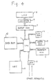
- FIG. 4 shows an electronic organizer according to the invention.
- the electronic organizer of Figure 4 comprises a CPU 1, a program ROM 2, a work RAM 3, a C.G. ROM 4, and an LCD 5, an LCD driver 6, a display RAM 7, a communication unit 8, a key unit 9, and a data RAM 10.
- the CPU 1 controls the entire electronic organizer by executing the program stored in the program ROM 2.
- the work RAM 3 is a RAM used as the work area when the CPU 1 conducts the control process.
- the C.G. ROM 4 is a ROM in which character patterns for display are stored.
- the LCD driver 6 converts character patterns in the display RAM 7 into electric signals, and supplies them to the LCD 5. Each bit in the display RAM 7 corresponds to one pixel in the LCD 5.
- the communication unit 8 sends and receives data to and from other apparatus.
- the key unit 9 includes numeral keys 91, character keys 92 (alphabet, kana (Japanese characters), etc.), SEARCH keys 93, a delete (DEL) key 94, an EDIT key 95, a SPECIAL FUNCTION key 96, and an ENTER key 97.
- the configuration of the data RAM 10 is shown in Figure 1A.
- the data RAM 10 has a plurality of data fields 11 and temporary deletion fields 12 which respectively correspond to the data fields 11.
- the data fields 11 store data
- the temporary deletion fields 12 store a special code or normal code.
- the temporary deletion fields 12 are used to distinguish whether or not the data in their corresponding data fields are in a temporarily deleted state (hereinafter, referred to as "temporary deletion state").
- the temporary deletion state is an intermediate data state in which the data has not been actually deleted; i.e., the data has not been erased from the data RAM 10.
- the special code is indicative that data stored in the data field 11 corresponding to the temporary deletion field 12 storing the special code stores data which is set to the temporary deletion state.
- the normal code is a predetermined code which is other than the special code, and indicates that data stored in the data field 11 corresponding to the temporary deletion field 12 storing the normal code stores data which is not set to the temporary deletion stats.
- the data field 11 can be either a fixed length or a variable length. In the case of variable length, the temporary deletion field 12 may be allocated to the delimiter area between data.
- Figure 1B shows the contents of the data RAM 10.
- two units of telephone directory data (a person's name and telephone number) are respectively stored in first and second data fields 11.
- the first temporary deletion field 12 stores the special code, and therefore data stored in the first data field 11 is in the temporary deletion state.
- data stored in the second data field 11 is not set to the temporary deletion state, and the second temporary deletion field 12 stores the normal code.
- step S1 When any key is pressed in step S1, the kind of pressed key is dis criminated in step S2.
- the process corresponding to the key pressed in step S1 is executed in step S3. For example, if one of the SEARCH keys 93 is pressed in step S1, the data is read out from the storage means in step S3 and displayed on the LCD 5 (this process is referred to as "call").
- step S1 When the DEL key 94 is pressed in step S1 after data has been called, the temporary deletion field 12 corresponding to the data field 11 storing that data is checked in step S51 to determine whether or not that the data is in the temporary deletion stats (ie., whether or not the temporary deletion field 12 stores the special code). If the data is not in the temporary deletion state (the temporary deletion field 12 stores the normal code), the process proceeds to step S52 in which the data is set to the temporary deletion state (i.e., the special code is stored in the corresponding temporary deletion field 12), and horizontal lines 20 are displayed over the data displayed in the LCD 5 as shown in Figure 3A to indicate that the data has been set to the temporary deletion state.
- the key operation for setting data to the temporary deletion state and the display of the LCD 5 corresponding to the key operation are shown in Figure 3A.
- the key operation shown in Figure 3A causes the data RAM 10 to attain the state shown in Figure 1B.
- the same key (the DEL key 94) is used for setting data to the temporary deletion state and also for actually deleting data which is the temporary deletion state.
- the present invention is not limited to this configuration.
- step S1 When the EDIT key 95 is pressed in step S1 after data has been called, the temporary deletion field 12 corresponding to the data field 11 storing that data is checked in step S41 to determine whether or not that the data is in the temporary deletion state. If the data is in the temporary deletion state i.e., the corresponding temporary deletion field 12 stores the special code) the contents of the corresponding temporary deletion field 12 are rewritten (from the special code to the normal code), and the temporary deletion state of the data is canceled (step S42). The horizontal lines 20 over the data in the LCD 5 are erased. The data edit mode is automatically set after the temporary deletion state of the data is canceled (step S43). When the present data is to be retained in the data RAM 10, the ENTER key 97 is then pressed.
- step S42 When the called data is not in the temporary deletion state, the process jumps step S42 to advance from step S41 to step S43.
- An example of key operations used in this embodiment to cancel the temporary deletion state of data and retain the data, and an example of the corresponding display are shown in Figure 3C.
- target data or data considered unnecessary can be tentatively set to the temporary deletion state, and after a certain period has elapsed, data which is truly unnecessary can be confirmed and deleted. Therefore, the danger of accidentally deleting data that are really necessary, which may occur in a prior art electronic apparatus, is avoided.
- the process may proceed to step S1 after the temporary deletion state is canceled in step S42.
- the electronic organizer may be designed so that the combined key operation of the SPECIAL FUNCTION key 96 and another key causes the batch deletion of all data which are in the temporary deletion state.
- the electronic apparatus of this invention has the utility of a paper notebook not found in prior art electronic apparatus, so it can be used with the same peace of mind as a paper notebook. An operator using the electronic apparatus of this invention can avoid the danger of accidentally deleting necessary data.
Landscapes
- Engineering & Computer Science (AREA)
- Theoretical Computer Science (AREA)
- Computing Systems (AREA)
- Computer Hardware Design (AREA)
- Physics & Mathematics (AREA)
- General Engineering & Computer Science (AREA)
- General Physics & Mathematics (AREA)
- Calculators And Similar Devices (AREA)
- Memory System (AREA)
Abstract
Description
- This invention is related to an electronic apparatus, and more particularly to an electronic apparatus having a memory means such as an electronic organizer.
- Compact electronic apparatus equipped with a memory means and a display means, and capable of storing data and displaying the recorded data using these means have come into wide use. Since these electronic apparatus are capable of recording telephone numbers, schedules and other data, they are expected to be used as a recording means for replacing the conventional paper pocket notebook. Below, as a typical example of such electronic apparatus, an electronic organizer will be described.
- An electronic organizer is provided with keys including numeral keys and character keys. The user uses these keys to store schedules, telephone numbers, memos and other data in an internal memory. The data entered using the character keys can also be converted to kanji (chinese characters) using a kanji conversion function. Further, data stored in the memory can be displayed as desired by operating keys.
- When deleting data stored in the memory, the data to be deleted (hereinafter, such data is referred to as "target data") is read from the memory to be displayed on a display device such as an LCD (Liquid Crystal Display), and then the delete key is pressed to delete the target data from the memory.
- Since the storage capacity of the memory means is limited in an electronic organizer, unnecessary data must be deleted. Once data is deleted in an electronic organizer, it is completely erased, so in order to recover deleted data, it must be re-entered. When deleting data, therefore, the user must carefully determine that he is deleting the data which is really unnecessary, in order to avoid accidentally deleting necessary data. This kind of problem in data deletion detracts from the availability or usability of an electronic organizer.
- The electronic apparatus of this invention, which overcomes the above-discussed and numerous other disadvantages and deficiencies of the prior art, comprises a memory means and a plurality of input keys, and further comprises: a temporary deletion means for, when a first predetermined key operation is performed, setting desired data which is stored in said memory means into a temporary deletion state; a deletion means for, when a second predetermined key operation is performed, deleting said data which has been set into the temporary deletion state from said memory means; and a release means for, when a third predetermined key operation is performed, releasing the temporary deletion state of said data which has been set into the temporary deletion state.
- In an embodiment, said memory means comprises a plurality of data fields and temporary deletion fields, said temporary deletion field corresponding to data fields, respectively, said temporary deletion means writes information in the temporary deletion field which corresponds to one of said data fields which stores data to be set to the temporary deletion state, said information being indicative that data stored in said data field corresponding to said temporary deletion field is in the temporary deletion state, and said release means rewrites information stored in the temporary deletion field to other information, said temporary deletion field corresponding to one of said data fields which stores data to be released from the temporary deletion state, said other information being indicative that said data stored in said corresponding data field is not in the temporary deletion state.
- In another embodiment, said deletion means deletes data stored in data fields which correspond respectively to temporary deletion fields storing said other information.
- In a further embodiment, said apparatus further comprises: a display device; a display means for reading desired data from said memory means and displaying said desired data on said display device; and a temporary deletion means for, when a first predetermined key operation is performed, setting data which is displayed on said display means to a temporary deletion state.
- In the above-mentioned construction, said apparatus further may comprise a marking means for, when data set to the temporary deletion state is displayed on said display device, displaying one or more marks together with the data displayed on said display device, said one or more marks being indicative that displayed data is in the temporary deletion state.
- Alternatively, said memory means comprises a plurality of data fields and temporary deletion fields, said temporary deletion fields corresponding to data fields, respectively, said temporary deletion means writes information in the temporary deletion field which corresponds to one of said data fields which stores data to be set to the temporary deletion state, said information being indicative that data stored in said data field corresponding to said temporary deletion field is in the temporary deletion state, and said release means rewrites information stored in the temporary deletion field to other information, said temporary deletion field corresponding to one of said data fields which stores data to be released from the temporary deletion state, said other information being indicative that said data stored in said corresponding data field is not in the temporary deletion state.
- In a further embodiment, said deletion means deletes data stored in data fields which correspond respectively to temporary deletion fields storing said other information.
- Thus, the invention described herein makes possible the objectives of:
- (1) providing an electronic apparatus in which the user can delete target data with peace of mind; and
- (2) providing an electronic apparatus in which target data can be temporarily deleted, and thereafter the user can decide to delete or to retain the target data.
- This invention may be better understood and its numerous objects and advantages will become apparent to chose skilled in the art by reference to the accompanying drawings as follows:
- Figure 1A shows diagrammatically the configuration of a memory means used in one embodiment of the invention.
- Figure 1B shows diagrammatically the contents of the memory means of Figure 1A.
- Figure 2 is a flowchart illustrating the operation of the embodiment.
- Figures 3A to 3C show the key operation sequences and the corresponding displays.
- Figure 4 is a block diagram of the embodiment.
- Figure 5 is a front view of the embodiment.
- Figure 4 shows an electronic organizer according to the invention. The electronic organizer of Figure 4 comprises a
CPU 1, aprogram ROM 2, awork RAM 3, a C.G. ROM 4, and an LCD 5, an LCD driver 6, adisplay RAM 7, a communication unit 8, akey unit 9, and adata RAM 10. TheCPU 1 controls the entire electronic organizer by executing the program stored in theprogram ROM 2. Thework RAM 3 is a RAM used as the work area when theCPU 1 conducts the control process. The C.G. ROM 4 is a ROM in which character patterns for display are stored. The LCD driver 6 converts character patterns in thedisplay RAM 7 into electric signals, and supplies them to the LCD 5. Each bit in thedisplay RAM 7 corresponds to one pixel in the LCD 5. The communication unit 8 sends and receives data to and from other apparatus. - As shown in Figure 5, the
key unit 9 includesnumeral keys 91, character keys 92 (alphabet, kana (Japanese characters), etc.),SEARCH keys 93, a delete (DEL) key 94, anEDIT key 95, aSPECIAL FUNCTION key 96, and anENTER key 97. - The configuration of the
data RAM 10 is shown in Figure 1A. Thedata RAM 10 has a plurality ofdata fields 11 andtemporary deletion fields 12 which respectively correspond to thedata fields 11. Thedata fields 11 store data, and thetemporary deletion fields 12 store a special code or normal code. Thetemporary deletion fields 12 are used to distinguish whether or not the data in their corresponding data fields are in a temporarily deleted state (hereinafter, referred to as "temporary deletion state"). The temporary deletion state is an intermediate data state in which the data has not been actually deleted; i.e., the data has not been erased from thedata RAM 10. The special code is indicative that data stored in thedata field 11 corresponding to thetemporary deletion field 12 storing the special code stores data which is set to the temporary deletion state. The normal code is a predetermined code which is other than the special code, and indicates that data stored in thedata field 11 corresponding to thetemporary deletion field 12 storing the normal code stores data which is not set to the temporary deletion stats. Thedata field 11 can be either a fixed length or a variable length. In the case of variable length, thetemporary deletion field 12 may be allocated to the delimiter area between data. - Figure 1B shows the contents of the
data RAM 10. In Figure 1B, two units of telephone directory data (a person's name and telephone number) are respectively stored in first andsecond data fields 11. in this case, the firsttemporary deletion field 12 stores the special code, and therefore data stored in thefirst data field 11 is in the temporary deletion state. By contrast, data stored in thesecond data field 11 is not set to the temporary deletion state, and the secondtemporary deletion field 12 stores the normal code. - The operation of the embodiment will be described with reference to Figure 2. When any key is pressed in step S1, the kind of pressed key is dis criminated in step S2. When a key other than the DEL key 94 or
EDIT key 95 is pressed, the process corresponding to the key pressed in step S1 is executed in step S3. For example, if one of theSEARCH keys 93 is pressed in step S1, the data is read out from the storage means in step S3 and displayed on the LCD 5 (this process is referred to as "call"). - When the DEL key 94 is pressed in step S1 after data has been called, the
temporary deletion field 12 corresponding to thedata field 11 storing that data is checked in step S51 to determine whether or not that the data is in the temporary deletion stats (ie., whether or not thetemporary deletion field 12 stores the special code). If the data is not in the temporary deletion state (thetemporary deletion field 12 stores the normal code), the process proceeds to step S52 in which the data is set to the temporary deletion state (i.e., the special code is stored in the corresponding temporary deletion field 12), andhorizontal lines 20 are displayed over the data displayed in the LCD 5 as shown in Figure 3A to indicate that the data has been set to the temporary deletion state. The key operation for setting data to the temporary deletion state and the display of the LCD 5 corresponding to the key operation are shown in Figure 3A. The key operation shown in Figure 3A causes thedata RAM 10 to attain the state shown in Figure 1B. - In this embodiment, the same key (the DEL key 94) is used for setting data to the temporary deletion state and also for actually deleting data which is the temporary deletion state. The present invention is not limited to this configuration.
- When the
EDIT key 95 is pressed in step S1 after data has been called, thetemporary deletion field 12 corresponding to thedata field 11 storing that data is checked in step S41 to determine whether or not that the data is in the temporary deletion state. If the data is in the temporary deletion state i.e., the correspondingtemporary deletion field 12 stores the special code) the contents of the correspondingtemporary deletion field 12 are rewritten (from the special code to the normal code), and the temporary deletion state of the data is canceled (step S42). Thehorizontal lines 20 over the data in the LCD 5 are erased. The data edit mode is automatically set after the temporary deletion state of the data is canceled (step S43). When the present data is to be retained in thedata RAM 10, theENTER key 97 is then pressed. When the called data is not in the temporary deletion state, the process jumps step S42 to advance from step S41 to step S43. An example of key operations used in this embodiment to cancel the temporary deletion state of data and retain the data, and an example of the corresponding display are shown in Figure 3C. - As described above, in the electronic organizer of this embodiment, target data or data considered unnecessary can be tentatively set to the temporary deletion state, and after a certain period has elapsed, data which is truly unnecessary can be confirmed and deleted. Therefore, the danger of accidentally deleting data that are really necessary, which may occur in a prior art electronic apparatus, is avoided.
- Alternatively, the process may proceed to step S1 after the temporary deletion state is canceled in step S42. In this case, it is preferable to provide a key for canceling the temporary deletion state which key is separate from the EDIT key.
- The electronic organizer may be designed so that the combined key operation of the
SPECIAL FUNCTION key 96 and another key causes the batch deletion of all data which are in the temporary deletion state. - It may be possible to dispose old data including temporarily deleted data by transferring them to an external storage device connected to the electronic organizer through the communication unit 8.
- According to the invention, stored data considered to be unnecessary can be tentatively deleted, and then the decision to actually delete the data or recover it can be made later. The electronic apparatus of this invention has the utility of a paper notebook not found in prior art electronic apparatus, so it can be used with the same peace of mind as a paper notebook. An operator using the electronic apparatus of this invention can avoid the danger of accidentally deleting necessary data.
- It is understood that various other modifications will be apparent to and can be readily made by those skilled in the art without departing from the scope and spirit of this invention. Accordingly, it is not intended that the scope of the claims appended hereto be limited to the description as set forth herein, but rather that the claims be construed as encompassing all the features of patentable novelty that reside in the present invention, including all features that could be treated as equivalents thereof by those skilled in the art to which this invention pertains.
Claims (7)
a temporary deletion means for, when a first predetermined key operation is performed, setting desired data which is stored in said memory means into a temporary deletion state;
a deletion means for, when a second predetermined key operation is performed, deleting said data which has been set into the temporary deletion state from said memory means; and
a release means for, when a third predetermined key operation is performed, releasing the temporary deletion state of said data which has been set into the temporary deletion state.
said temporary deletion means writes information in the temporary deletion field which corresponds to one of said data fields which stores data to be set to the temporary deletion state, said information being indicative that data stored in said data field corresponding to said temporary deletion field is in the temporary deletion state, and
said release means rewrites information stored in the temporary deletion field to other information, said temporary deletion field corresponding to one of said data fields which stores data to be released from the temporary deletion state, said other information being indicative that said data stored in said corresponding data field is not in the temporary deletion state.
a display device;
a display means for reading desired data from said memory means and displaying said desired data on said display device; and
a temporary deletion means for, when a first predetermined key operation is performed, setting data which is displayed on said display means to a temporary deletion state.
said temporary deletion means writes
information in the temporary deletion field which corresponds to one of said data fields which stores data to be set to the temporary deletion state, said information being indicative that data stored in said data field corresponding to said temporary deletion field is in the temporary deletion state, and
said release means rewrites information stored in the temporary deletion field to other information, said temporary deletion field corresponding to one of said data fields which stores data to be released from the temporary deletion state, said other information being indicative that said data stored in said corresponding data field is not in the temporary deletion state.
Applications Claiming Priority (2)
| Application Number | Priority Date | Filing Date | Title |
|---|---|---|---|
| JP176343/89 | 1989-07-07 | ||
| JP1176343A JP2966432B2 (en) | 1989-07-07 | 1989-07-07 | Electronics |
Publications (3)
| Publication Number | Publication Date |
|---|---|
| EP0406895A2 true EP0406895A2 (en) | 1991-01-09 |
| EP0406895A3 EP0406895A3 (en) | 1992-01-02 |
| EP0406895B1 EP0406895B1 (en) | 1998-02-04 |
Family
ID=16011931
Family Applications (1)
| Application Number | Title | Priority Date | Filing Date |
|---|---|---|---|
| EP90112953A Expired - Lifetime EP0406895B1 (en) | 1989-07-07 | 1990-07-06 | An electronic apparatus |
Country Status (4)
| Country | Link |
|---|---|
| US (1) | US5488720A (en) |
| EP (1) | EP0406895B1 (en) |
| JP (1) | JP2966432B2 (en) |
| DE (1) | DE69032019T2 (en) |
Cited By (2)
| Publication number | Priority date | Publication date | Assignee | Title |
|---|---|---|---|---|
| DE9200832U1 (en) * | 1992-01-24 | 1992-10-08 | Lieske, Alexander, 3394 Langelsheim, De | |
| EP0575982A2 (en) * | 1992-06-24 | 1993-12-29 | Sharp Kabushiki Kaisha | Electronic notebook and planner |
Families Citing this family (8)
| Publication number | Priority date | Publication date | Assignee | Title |
|---|---|---|---|---|
| JPH06128944A (en) * | 1992-04-27 | 1994-05-10 | Hara Mitsuo | Agitation blade structure for subsoil improvement device |
| US7039177B1 (en) | 2000-09-13 | 2006-05-02 | International Business Machines Corp. | Automatic update of a directory entry within a directory of an electronic communication device by electronic notification |
| US7058664B1 (en) * | 2002-04-29 | 2006-06-06 | Sprint Communications Company L.P. | Method and system for data recovery |
| US7614007B2 (en) * | 2004-01-16 | 2009-11-03 | International Business Machines Corporation | Executing multiple file management operations |
| FR2872937B1 (en) * | 2004-07-08 | 2006-10-20 | Pascal Lucchina | SECURED PROGRAMMABLE PERSONAL DEVICE FOR STORAGE AND RESTITUTION OF DATA |
| US8352448B2 (en) * | 2007-01-23 | 2013-01-08 | International Business Machines Corporation | Securely deleting data in a transactionally consistent manner |
| JP5267612B2 (en) * | 2011-04-22 | 2013-08-21 | 大日本印刷株式会社 | IC module for IC card, IC card and IC card program |
| US10410948B2 (en) | 2015-01-30 | 2019-09-10 | Netgear, Inc. | Integrated heat sink and electromagnetic interference (EMI) shield assembly |
Citations (1)
| Publication number | Priority date | Publication date | Assignee | Title |
|---|---|---|---|---|
| EP0272821A2 (en) * | 1986-12-24 | 1988-06-29 | Hewlett-Packard Company | Method and apparatus for computation stack recovery in a calculator |
Family Cites Families (19)
| Publication number | Priority date | Publication date | Assignee | Title |
|---|---|---|---|---|
| US3585601A (en) * | 1969-08-19 | 1971-06-15 | Kaiser Aluminium Chem Corp | Remote input management system |
| JPS5776660A (en) * | 1980-10-31 | 1982-05-13 | Toshiba Corp | Recording system for variable-length picture information |
| US4633736A (en) * | 1982-12-06 | 1987-01-06 | Aisin-Warner Kabushiki Kaisha | Vehicular continuously variable transmission |
| JPS6120173A (en) * | 1984-07-06 | 1986-01-28 | Nec Corp | Restoring method of source text |
| JPS6182227A (en) * | 1984-08-29 | 1986-04-25 | Fujitsu Ltd | Full screen data deleting system |
| JPS61260339A (en) * | 1985-05-15 | 1986-11-18 | Oki Electric Ind Co Ltd | File control method |
| JPH0619777B2 (en) * | 1985-08-28 | 1994-03-16 | 株式会社東芝 | Text editing system |
| US4847754A (en) * | 1985-10-15 | 1989-07-11 | International Business Machines Corporation | Extended atomic operations |
| JPS62163153A (en) * | 1986-01-13 | 1987-07-18 | Mitsubishi Electric Corp | Restoration processing system for deleted file |
| JPS62164159A (en) * | 1986-01-16 | 1987-07-20 | Matsushita Electric Ind Co Ltd | Word processor |
| US4807182A (en) * | 1986-03-12 | 1989-02-21 | Advanced Software, Inc. | Apparatus and method for comparing data groups |
| US5113517A (en) * | 1986-04-28 | 1992-05-12 | Xerox Corporation | Concurrent display of data from two different processors each having different display font and user interface for controlling transfer of converted font data therebetween |
| JPS6386042A (en) * | 1986-09-30 | 1988-04-16 | Ricoh Co Ltd | Restoring system for erasion file |
| JPS63138442A (en) * | 1986-11-29 | 1988-06-10 | Fujitsu Ltd | Restoring and processing system for deleted file |
| US4853878A (en) * | 1987-05-01 | 1989-08-01 | International Business Machines Corp. | Computer input by color coding |
| US4807111A (en) * | 1987-06-19 | 1989-02-21 | International Business Machines Corporation | Dynamic queueing method |
| US5261080A (en) * | 1987-08-21 | 1993-11-09 | Wang Laboratories, Inc. | Matchmaker for assisting and executing the providing and conversion of data between objects in a data processing system storing data in typed objects having different data formats |
| JP3020500B2 (en) * | 1988-01-29 | 2000-03-15 | 株式会社日立製作所 | Database system having memo information and method of managing memo information |
| US5144659A (en) * | 1989-04-19 | 1992-09-01 | Richard P. Jones | Computer file protection system |
-
1989
- 1989-07-07 JP JP1176343A patent/JP2966432B2/en not_active Expired - Fee Related
-
1990
- 1990-07-06 DE DE69032019T patent/DE69032019T2/en not_active Expired - Lifetime
- 1990-07-06 EP EP90112953A patent/EP0406895B1/en not_active Expired - Lifetime
-
1995
- 1995-02-08 US US08/385,581 patent/US5488720A/en not_active Expired - Lifetime
Patent Citations (1)
| Publication number | Priority date | Publication date | Assignee | Title |
|---|---|---|---|---|
| EP0272821A2 (en) * | 1986-12-24 | 1988-06-29 | Hewlett-Packard Company | Method and apparatus for computation stack recovery in a calculator |
Non-Patent Citations (1)
| Title |
|---|
| Benutzer- Handbuch für Bürokommunikationssysteme SIEMENS AG, 1986, no. A30820-A5803-V10-2-18 pages 0/1, 2/4, 9/3, 9/5-9/8 * |
Cited By (4)
| Publication number | Priority date | Publication date | Assignee | Title |
|---|---|---|---|---|
| DE9200832U1 (en) * | 1992-01-24 | 1992-10-08 | Lieske, Alexander, 3394 Langelsheim, De | |
| EP0575982A2 (en) * | 1992-06-24 | 1993-12-29 | Sharp Kabushiki Kaisha | Electronic notebook and planner |
| EP0575982A3 (en) * | 1992-06-24 | 1995-03-22 | Sharp Kk | Electronic notebook and planner. |
| US5568451A (en) * | 1992-06-24 | 1996-10-22 | Sharp Kabushiki Kaisha | Compact electronic apparatus |
Also Published As
| Publication number | Publication date |
|---|---|
| EP0406895B1 (en) | 1998-02-04 |
| US5488720A (en) | 1996-01-30 |
| DE69032019D1 (en) | 1998-03-12 |
| JP2966432B2 (en) | 1999-10-25 |
| JPH0340166A (en) | 1991-02-20 |
| EP0406895A3 (en) | 1992-01-02 |
| DE69032019T2 (en) | 1998-09-03 |
Similar Documents
| Publication | Publication Date | Title |
|---|---|---|
| EP0406895A2 (en) | An electronic apparatus | |
| JPH0564823B2 (en) | ||
| US5125078A (en) | Electronic display apparatus with scrolling function | |
| EP0453246B1 (en) | A communication apparatus capable of connecting memory card | |
| JPH0778544B2 (en) | Schedule display device | |
| JPH0520275A (en) | Compact information terminal equipment | |
| JP2698235B2 (en) | Small information terminal | |
| JPH0335355A (en) | Electronic equipment | |
| JP4399238B2 (en) | INPUT GUIDE DEVICE, PORTABLE TERMINAL HAVING THE SAME, COMPUTER CONTROL METHOD AND PROGRAM FOR THE SAME | |
| JP3274312B2 (en) | Information processing device | |
| JP2701089B2 (en) | Information transfer method | |
| JPH09146892A (en) | Electronic equipment | |
| JP3368039B2 (en) | Electronic equipment | |
| EP0364099B1 (en) | Data storage and retrieval in a calculator | |
| KR0175028B1 (en) | How to save and restore erased data in small memory | |
| KR970007610B1 (en) | Pager | |
| JP2749023B2 (en) | Small electronic equipment | |
| JPH04369965A (en) | Facsimile equipment having memory expantion function | |
| JPH02120979A (en) | Data control device | |
| JP2001236297A (en) | Information equipment and peripheral equipment of the same | |
| JPS62107561A (en) | Telephone set | |
| JP3265708B2 (en) | Prohibition processing setting device | |
| JPH0535682A (en) | Information memory | |
| JPH0522265B2 (en) | ||
| JPS63140328A (en) | Recording system for computer terminal equipment |
Legal Events
| Date | Code | Title | Description |
|---|---|---|---|
| PUAI | Public reference made under article 153(3) epc to a published international application that has entered the european phase |
Free format text: ORIGINAL CODE: 0009012 |
|
| AK | Designated contracting states |
Kind code of ref document: A2 Designated state(s): DE FR GB |
|
| 17P | Request for examination filed |
Effective date: 19901221 |
|
| PUAL | Search report despatched |
Free format text: ORIGINAL CODE: 0009013 |
|
| AK | Designated contracting states |
Kind code of ref document: A3 Designated state(s): DE FR GB |
|
| 17Q | First examination report despatched |
Effective date: 19960308 |
|
| GRAG | Despatch of communication of intention to grant |
Free format text: ORIGINAL CODE: EPIDOS AGRA |
|
| GRAG | Despatch of communication of intention to grant |
Free format text: ORIGINAL CODE: EPIDOS AGRA |
|
| GRAH | Despatch of communication of intention to grant a patent |
Free format text: ORIGINAL CODE: EPIDOS IGRA |
|
| GRAH | Despatch of communication of intention to grant a patent |
Free format text: ORIGINAL CODE: EPIDOS IGRA |
|
| GRAA | (expected) grant |
Free format text: ORIGINAL CODE: 0009210 |
|
| AK | Designated contracting states |
Kind code of ref document: B1 Designated state(s): DE FR GB |
|
| REF | Corresponds to: |
Ref document number: 69032019 Country of ref document: DE Date of ref document: 19980312 |
|
| ET | Fr: translation filed | ||
| PLBE | No opposition filed within time limit |
Free format text: ORIGINAL CODE: 0009261 |
|
| STAA | Information on the status of an ep patent application or granted ep patent |
Free format text: STATUS: NO OPPOSITION FILED WITHIN TIME LIMIT |
|
| 26N | No opposition filed | ||
| REG | Reference to a national code |
Ref country code: GB Ref legal event code: IF02 |
|
| PGFP | Annual fee paid to national office [announced via postgrant information from national office to epo] |
Ref country code: FR Payment date: 20090710 Year of fee payment: 20 |
|
| PGFP | Annual fee paid to national office [announced via postgrant information from national office to epo] |
Ref country code: DE Payment date: 20090702 Year of fee payment: 20 Ref country code: GB Payment date: 20090701 Year of fee payment: 20 |
|
| REG | Reference to a national code |
Ref country code: GB Ref legal event code: PE20 Expiry date: 20100705 |
|
| PG25 | Lapsed in a contracting state [announced via postgrant information from national office to epo] |
Ref country code: GB Free format text: LAPSE BECAUSE OF EXPIRATION OF PROTECTION Effective date: 20100705 |
|
| PG25 | Lapsed in a contracting state [announced via postgrant information from national office to epo] |
Ref country code: DE Free format text: LAPSE BECAUSE OF EXPIRATION OF PROTECTION Effective date: 20100706 |