EP0406783A2 - Process for making hollow articles from lignocellulosic fibres - Google Patents
Process for making hollow articles from lignocellulosic fibres Download PDFInfo
- Publication number
- EP0406783A2 EP0406783A2 EP90112631A EP90112631A EP0406783A2 EP 0406783 A2 EP0406783 A2 EP 0406783A2 EP 90112631 A EP90112631 A EP 90112631A EP 90112631 A EP90112631 A EP 90112631A EP 0406783 A2 EP0406783 A2 EP 0406783A2
- Authority
- EP
- European Patent Office
- Prior art keywords
- mold
- molded part
- water
- suspension
- binder
- Prior art date
- Legal status (The legal status is an assumption and is not a legal conclusion. Google has not performed a legal analysis and makes no representation as to the accuracy of the status listed.)
- Granted
Links
Images

Classifications
-
- D—TEXTILES; PAPER
- D21—PAPER-MAKING; PRODUCTION OF CELLULOSE
- D21J—FIBREBOARD; MANUFACTURE OF ARTICLES FROM CELLULOSIC FIBROUS SUSPENSIONS OR FROM PAPIER-MACHE
- D21J3/00—Manufacture of articles by pressing wet fibre pulp, or papier-mâché, between moulds
Definitions
- the invention relates to a method for producing molded parts with a spatial shape from lignocellulose-containing fibers according to the preamble of the main claim.
- molded parts with a spatial shape from lignocellulose-containing chips and fibers is preferably carried out by the pressing process, i.e. the spreading process is followed by the pressing process.
- the strength of the molded parts produced in this way is also sufficient for larger dimensions.
- These are mostly synthetic resin-bonded molded parts with a resin content of 4 to 20%. These molded parts are expensive. Environmentally harmful substances are emitted when such molded parts are burned. Both are disadvantageous.
- a casting process is known according to which molded parts are produced from fibers containing lignocellulose (porous fiberboard) without subsequent pressing.
- the fiber suspension is placed in a casting box and the excess water is then expelled using vacuum or gravity.
- These panels have a strength which, due to the low material density, is not sufficient for a wide range of applications. If spatial molded parts of larger dimensions are made from it, in which heavy objects may also have to be transported, the strengths are not sufficient. If you want to achieve higher strengths, the walls and the bottom of such molded parts must have a disproportionately large wall thickness. This is disadvantageous, the applicability or usability of such molded parts is thereby limited.
- the coffin industry relies on solid wood coffins to deliver, since the use of legends from lignocellulose-containing shavings and fibers has so far failed for the reasons mentioned above (no emissions, high costs, insufficient strength).
- a further production process for molded parts made of lignocellulose-containing fibers is known (VDI-Nachschreib (No. 32 / August 12, 1988).
- An aqueous slurry of lignocellulose-containing material is then poured into a casting mold and the water is then suctioned off with a vacuum.
- the raw mass dries into With this procedure it is important that the resulting pressure drop acts evenly over the entire cross-section of the mold. If this is not done, a molded part with an uneven thickness and material density distribution is created. To avoid this, nonwovens / fibreboards are used in the production This possibility does not exist in the production of molded parts.
- molded parts made of cast fiber according to the known method have inaccurate dimensions and uneven density distribution. This is disadvantageous.
- the object of the invention is to provide a method for producing molded parts with spatial shaping from lignocellulose-containing fibers, according to which the molded part is easy to produce and has controllable strengths even with complicated profiling while maintaining uniform density distribution and dimensions.
- the molded part By producing the molded part by the process according to the invention in such a way that the water-binder fiber suspension is introduced into a mold under pressure, it is achieved that a molded part with a uniform density distribution is produced both in the bottom section and in the walls. Even with molded parts with a complicated profile, a uniform density distribution can be achieved in the entire molded part.
- a variable part with the desired strength is produced by the variable setting of the pressure and the underpressure required for suctioning off the excess water.
- the application of pressure means that the thickness of the floor and walls can be controlled.
- the molded parts produced by casting with pressure application have no points that are not sufficiently compressed and thereby lower the strength of the molded part.
- the fiber content of the suspension can be increased so that the volume of the material to be introduced is significantly smaller than in the manufacturing process without pressure. Due to the application of pressure, the entire manufacturing process takes considerably less time than comparable processes without using pressure. In this way, the economy of the manufacturing process can be significantly increased.
- smaller mold dimensions are required when the suspension is introduced under pressure than during the manufacturing process without applying pressure.
- the bottom section of the molded part can be produced separately from the walls. This is particularly advantageous if e.g. the floor should have different strengths or material density than the walls. Furthermore, this method of producing the molded part in two steps is particularly advantageous when it concerns molded parts with a large floor area.
- the procedure can be such that the suspension introduced into the mold is additionally mechanically compressed.
- One way of carrying out the compression process is to lower a compression stamp into the mold.
- the additional mechanical compression is always chosen when the molded parts to be manufactured are subject to particularly high demands in terms of strength and density.
- the density of the moldings according to the invention is preferably 150 kg / m3 to 350 kg / m3.
- the corresponding bending strength values are between 1.2 N / mm2. It can be determined by the fiber mass to be dosed and the choice of pressure and vacuum to be used. This predetermined material density can be adhered to exactly by the method according to the invention.
- a manufacturing process for molded parts with spatial shaping from lignocellulosic fibers is specified, in which the suspension introduced into a mold is compressed twice.
- the A individual compression processes are independent of each other; the first compression process serves to compress the bottom section of the molded part, the second compression process serves to compress the walls of the molded part to be produced.
- the density of the walls and the bottom section can be the same or different.
- the strengths of these two parts of the molded part can be the same or different. This can be easily achieved by using the two-stage compression process.
- the mechanical compression takes place by means of stamps which can be lowered into the mold.
- the first punch which can be lowered into the mold and which serves to compress the bottom section is selected such that it also serves as a rough shape for the walls.
- the variation of the thickness dimensions of the bottom section and the walls can be realized either by appropriate travel paths of the punches or by using different punches.
- the former alternative is particularly inexpensive and simple in terms of device.
- the water is expelled by gravity or vacuum.
- the part is preferably dried at 180 ° C. In the case of parts with an average wall thickness of approximately 2 cm, the drying time is approximately one and a half to two hours. If the molded part remains in the outer or inner mold during the drying process, the convex wall deformations that occur due to the tensile stresses during drying in the direction of the molded part center are prevented.
- the economy of the process according to the invention is significantly increased in that the water-binder suspension is used in the recycling process.
- the fiber suspension used to manufacture the molded parts can consist of 100% defibrator wood pulp with vegetable binders. It is advantageous if the binding and adhesive agent forms a neutral colloidal solution with water, at the same time fulfilling the function of a suspending agent.
- the molded parts produced by the process according to the invention have the advantages already described, such as uniform density distribution in the entire molded part, uniform strength in the entire molded part or uniform density and strength distribution only in the bottom section or only in the walls, ie a targeted reinforcement of a part of the molded part possible.
- the molded part has additional stiffeners, the insertion of bottom or side reinforcements in the manufacturing process is not problematic.
- the methods according to the invention are not limited to the production of molded parts of smaller dimensions. Molded parts can be produced that have a complicated profile and have a size of a few meters. This is possible because, due to the application of pressure or compression during the manufacturing process, the strength of the molded part is much higher than when manufacturing without pressure and without compression. In addition, the strength of the molded part can be adjusted according to the requirements by varying the pressure and the negative pressure
- the processing of the finished molded part is possible as with solid wood.
- the methods according to the invention can preferably be used for the production of molded parts for the coffin industry. These processes are also suitable for the production of molded parts for the packaging industry, gardening supplies or insulation purposes.
- the shape can consist of two parts, an inner and an outer shape.
- This advantageous embodiment is particularly useful when the wall thickness or the base thickness of the molded part is to be varied while maintaining the external dimensions. This can be set according to the proposed solution of claim 13 via the distance between the two forms.
- the outer shape advantageously has perforations on the bottom and on the sides. These allow a simple drainage process due to negative pressure or gravity.
- a device which has a stamp which can be lowered from above into an outer shape perforated on the side and / or bottom. At the same time, this stamp has the function of limiting the filling space for the suspension.
- a device which has an outer shape provided with bottom and side perforations and has a pouring plunger that can be lowered from above.
- the casting ram compresses the bottom section and, in cooperation with the outer shape, represents a raw contour for the walls of the molded part.
- a further ram that can be lowered into the outer shape is provided to compress the walls.
- the device for performing the method has a casting box 1, consisting of a lower part 1 'and upper part 1 ⁇ , an outer shape 2 provided with lateral and bottom perforations and a compression ram 3.
- feed channels 4 are provided for entering the suspension.
- the following process sequence results:
- the suspension 5 is introduced through the channels 4 into the outer mold 2 under pressure. If the filling space 5 ', which is limited by the walls of the outer shape 2 and the inner walls of the stamp 3, filled with suspension, the stamp 3 is lowered, the suspension supply is interrupted. At the same time, the excess water is expelled from the suspension 5 by means of negative pressure, which is facilitated by the perforations made in the outer mold 2.
- the molded part 6 thus produced is then dried at an elevated temperature and heat treated.
- the device has the following components: a mixer 7, a metering pump 8, an outer mold 10, which is attached in a casting box 9 and is perforated on the bottom and sides, a separator 11, a vacuum reservoir 12, a vacuum pump 13, a casting ram 14, a ram 15, a separate, perforated inner mold 16 and a drying cabinet 17.
- the procedure is as follows: A suspension in the mixer 7 is produced from the constituents water (A), fibers (B) and binder (C) with the addition of the expelled water with binder constituents (D). The suspension is poured into the perforated outer mold 10, which is inserted between the upper and lower part of the casting box 9.
- the casting process is interrupted and the sedimentation of the fibers waited until no more water flows from the separator 11.
- the casting die 14 is placed centrally in the outer mold 10, the cast fiber flow being compressed by its own weight and / or mechanical pressure.
- the molding base 18 is produced by this process.
- Molded walls 19 are then produced by pouring the suspension into the space between the outer contour of the die 14 and the inner contour of the outer mold 10 up to the height where the die 14 has the greatest width.
- the sedimentation of the fibers is waited until no more water flows out of the separator 11.
- the casting die 5 is now removed from the mold and the press die 15 is retracted. Only the walls 19 of the molded part are compressed by the mechanical pressure.
Landscapes
- Engineering & Computer Science (AREA)
- Manufacturing & Machinery (AREA)
- Dry Formation Of Fiberboard And The Like (AREA)
- Artificial Filaments (AREA)
- Separation Using Semi-Permeable Membranes (AREA)
- Paper (AREA)
- Compositions Of Macromolecular Compounds (AREA)
Abstract
Es wird ein Verfahren zur Herstellung von Formteilen mit räumlicher Formgebung aus lignocellulosehaltigen Fasern mit pflanzlichen Bindemitteln vorgestellt, durch welches Formteile (20) herstellbar sind, welche auch bei einer komplizierten Profilierung eine gleichmäßige Dichteverteilung aufweisen. Die Abmessungen der Formteile (20) sowie ihre Festigkeit sind durch das vorgestellte Herstellungsverfahren kontrollierbar. Eine gezielte Einstellung der Dichte und der Festigkeit im Formteil ist durch das beschriebene Verfahren möglich. Die Merkmale des Herstellungsverfahrens sind: Einbringen der Suspension in die Form unter Druck und Verdichten der Teile (18,19) des Formteiles. 
Description
Die Erfindung betrifft ein Verfahren zur Herstellung von Formteilen mit räumlicher Formgebung aus lignocellulosehaltigen Fasern gemäß dem Oberbegriff des Hauptanspruches.The invention relates to a method for producing molded parts with a spatial shape from lignocellulose-containing fibers according to the preamble of the main claim.
Die Herstellung von Formteilen mit räumlicher Formgebung aus lignocellulosehaltigen Spänen und Fasern erfolgt bei den geforderten Festigkeiten vorzugsweise im Preßverfahren, d.h. an den Streuvorgang schließt sich der Vorgang des Pressens an. Die Festigkeiten der so hergestellten Formteile reichen auch für größere Abmessungen. Es handelt sich dabei meistens um kunstharzgebundene Formteile mit Harzanteilen von 4 bis 20%. Diese Formteile sind teuer. Bei der Verbrennung solcher Formteile werden umweltbelastende Stoffe emittiert. Beides ist nachteilig.The production of molded parts with a spatial shape from lignocellulose-containing chips and fibers is preferably carried out by the pressing process, i.e. the spreading process is followed by the pressing process. The strength of the molded parts produced in this way is also sufficient for larger dimensions. These are mostly synthetic resin-bonded molded parts with a resin content of 4 to 20%. These molded parts are expensive. Environmentally harmful substances are emitted when such molded parts are burned. Both are disadvantageous.
Daneben ist ein Gießverfahren bekannt, nach dem Formteile aus lignocellulosehaltigen Fasern (poröse Faserplatten) ohne anschließendes Pressen hergestellt werden. Dabei wird die Faser-Suspension in einen Gießkasten eingebracht und das überschüssige Wasser anschließend mittels Vakuum oder durch Schwerkraft ausgetrieben. Diese Platten weisen eine Festigkeit auf, die durch die geringe Materialdichte bedingt, nicht für eine breite Palette von Anwendungen ausreicht. Werden daraus räumliche Formteile von größeren Abmessungen hergestellt, in denen eventuell auch schwere Gegenstände transportiert werden müssen, reichen die Festigkeiten nicht aus. Will man höhere Festigkeiten erreichen, so müssen die Wandungen und der Boden solcher Formteile eine unverhältnismäßig große Wandstärke aufweisen. Dies ist nachteilig, die Anwendbarkeit, bzw. Verwendbarkeit solcher Formteile wird dadurch begrenzt. So ist z.B. die Sarg-Industrie darauf angewiesen, Särge aus Massivholz her zustellen, da die Verwendung von Sagen aus lignocellulosehaltigen Spänen und Fasern bisher aus den obengenannten Gründen (keine Emissionsfreiheit, hohe Kosten, nicht ausreichende Festigkeiten) scheiterte.In addition, a casting process is known according to which molded parts are produced from fibers containing lignocellulose (porous fiberboard) without subsequent pressing. The fiber suspension is placed in a casting box and the excess water is then expelled using vacuum or gravity. These panels have a strength which, due to the low material density, is not sufficient for a wide range of applications. If spatial molded parts of larger dimensions are made from it, in which heavy objects may also have to be transported, the strengths are not sufficient. If you want to achieve higher strengths, the walls and the bottom of such molded parts must have a disproportionately large wall thickness. This is disadvantageous, the applicability or usability of such molded parts is thereby limited. For example, the coffin industry relies on solid wood coffins to deliver, since the use of legends from lignocellulose-containing shavings and fibers has so far failed for the reasons mentioned above (no emissions, high costs, insufficient strength).
Es ist ein weiteres Herstellungsverfahren für Formteile aus lignocellulosehaltigen Fasern bekannt (VDI-Nachrichten (Nr.32/ 12. August 1988). Danach wird ein wässriger Brei aus lignocellulosehaltigem Material in eine Gießform gegossen und das Wasser anschließend mit Vakuum abgesaugt. Die Rohmasse trocknet in einem Trockenkanal. Bei dieser Vorgehensweise ist es wichtig, daß das entstehende Druckgefälle gleichmäßig über den ganzen Querschnitt der Form wirkt. Geschieht dies nicht, so entsteht ein Formteil mit ungleichmäßiger Dicke und Materialdichteverteilung. Um dies zu vermeiden, werden bei der Herstellung von Vliesen/Faserplatten entsprechende Leitbleche eingesetzt. Bei Herstellung von Formteilen besteht diese Möglichkeit nicht. Somit weisen die nach dem bekannten Verfahren hergestellten Formteile aus Faserguß ungenaue Abmessungen und ungleiche Dichteverteilung auf. Dies ist nachteilig.A further production process for molded parts made of lignocellulose-containing fibers is known (VDI-Nachrichten (No. 32 / August 12, 1988). An aqueous slurry of lignocellulose-containing material is then poured into a casting mold and the water is then suctioned off with a vacuum. The raw mass dries into With this procedure it is important that the resulting pressure drop acts evenly over the entire cross-section of the mold. If this is not done, a molded part with an uneven thickness and material density distribution is created. To avoid this, nonwovens / fibreboards are used in the production This possibility does not exist in the production of molded parts. Thus, molded parts made of cast fiber according to the known method have inaccurate dimensions and uneven density distribution. This is disadvantageous.
Aufgabe der Erfindung ist es, ein Verfahren zur Herstellung von Formteilen mit räumlicher Formgebung aus lignocellulosehaltigen Fasern anzugeben nach dem das Formteil einfach herzustellen ist und auch bei einer komplizierten Profilierung unter Einhaltung gleichmäßiger Dichteverteilung und Abmessungen kontrollierbare Festigkeiten aufweist.The object of the invention is to provide a method for producing molded parts with spatial shaping from lignocellulose-containing fibers, according to which the molded part is easy to produce and has controllable strengths even with complicated profiling while maintaining uniform density distribution and dimensions.
Diese Aufgabe ist gemäß der Erfindung durch die kennzeichnenden Merkmale der Ansprüche 1 und 4 gelöst. Die Unteransprüche stellen vorteilhafte Weiterbildungen dar.This object is achieved according to the invention by the characterizing features of
Durch die Herstellung des Formteiles nach dem erfindungsgemäßen Verfahren derart, daß die Wasser-Bindemittel-Faser-Suspension unter Druck in eine Form eingebracht wird, wird erreicht, daß ein Formteil mit gleichmäßiger Dichteverteilung sowohl im bodenseitigen Abschnitt als auch in den Wandungen entsteht. Auch bei Formteilen mit einer komplizierten Profilierung ist dadurch eine gleichmäßige Dichteverteilung im gesamten Formteil erreichbar. Durch die variable Einstellung des Druckes und des zum Absaugen des Überschußwassers notwendigen Unterdrukkes wird ein Formteil mit gewünschter Festigkeit hergestellt. Des weiteren ist durch die Druckanwendung erreichbar, daß die Stärke des Bodens und der Wandungen kontrollierbar ist. Durch das Einbringen der Suspension durch Gießen unter Druck und gleichzeitiges Absaugen des Überschußwassers mittels einer Vakuumpumpe wird wesentlich weniger Vakuum benötigt, als beim Gießen ohne Druck. Somit sinkt der Energiebedarf. Die durch Gießen mit Druckanwendung hergestellten Formteile weisen keine Stellen auf, die nicht genügend verdichtet sind und dadurch die Festigkeit des Formteiles senken. Durch die Anwendung des Druckes kann der Faserstoffgehalt der Suspension erhöht werden, so daß das Volumen des einzubringenden Materials wesentlich kleiner ist als beim Herstellungsvorgang ohne Druck. Das gesamte Herstellungsverfahren dauert durch die Druckanwendung wesentlich kürzer als vergleichbare Verfahren ohne Druckanwendung. Die Wirtschaftlichkeit des Herstellungsprozesses kann auf diese Weise also wesentlich gesteigert werden. Außerdem werden bei gleichgroßen Formteilen bei Einbringen der Suspension unter Druck kleinere Formabmessungen benötigt als beim Herstellungsvorgang ohne Druckanwendung.By producing the molded part by the process according to the invention in such a way that the water-binder fiber suspension is introduced into a mold under pressure, it is achieved that a molded part with a uniform density distribution is produced both in the bottom section and in the walls. Even with molded parts with a complicated profile, a uniform density distribution can be achieved in the entire molded part. A variable part with the desired strength is produced by the variable setting of the pressure and the underpressure required for suctioning off the excess water. Furthermore, the application of pressure means that the thickness of the floor and walls can be controlled. By introducing the suspension by casting under pressure and simultaneous suction of the excess water using a vacuum pump requires significantly less vacuum than when casting without pressure. This reduces the energy requirement. The molded parts produced by casting with pressure application have no points that are not sufficiently compressed and thereby lower the strength of the molded part. By applying the pressure, the fiber content of the suspension can be increased so that the volume of the material to be introduced is significantly smaller than in the manufacturing process without pressure. Due to the application of pressure, the entire manufacturing process takes considerably less time than comparable processes without using pressure. In this way, the economy of the manufacturing process can be significantly increased. In addition, with molded parts of the same size, smaller mold dimensions are required when the suspension is introduced under pressure than during the manufacturing process without applying pressure.
Gemäß Lösungsvorschlag des Ansprüches 2 wird erreicht, daß der bodenseitige Abschnitt des Formteiles getrennt von den Wandungen hergestellt werden kann. Dies ist besonders dann von Vorteil, wenn z.B. der Boden andere Festigkeiten bzw. Materialdichte aufweisen soll als die Wandungen. Weiterhin ist dieses Verfahren der Herstellung des Formteiles in zwei Schritten besonders dann vorteilhaft, wenn es sich um Formteile mit einer flächenmäßig großen Bodenausdehnung handelt.According to the proposed solution of
In Ausgestaltung des erfindungsgemäßen Herstellungsverfahrens kann so vorgegangen werden, daß die in die Form eingebrachte Suspension zusätzlich mechanisch verdichtet wird. Eine Möglichkeit der Ausführung des Verdichtungsvorganges ist das Absenken eines Verdichtungsstempels in die Form. Die zusätzliche mechanische Verdichtung wird immer dann gewählt, wenn an die herzustellenden Formteile besonders hohe Anforderungen bezüglich Festigkeit und Dichte gestellt werden.In an embodiment of the production method according to the invention, the procedure can be such that the suspension introduced into the mold is additionally mechanically compressed. One way of carrying out the compression process is to lower a compression stamp into the mold. The additional mechanical compression is always chosen when the molded parts to be manufactured are subject to particularly high demands in terms of strength and density.
Die Dichte der erfindungsgemäßen Formteile beträgt vorzugsweise 150 kg/m³ bis 350 kg/m³. Die entsprechenden Biegefestigkeitswerte liegen zwischen 1,2 N/mm². Sie kann durch die zu dosierende Fasermasse und die Wahl des anzuwendenden Druckes und Unterdruckes bestimmt werden. Diese vorgegebene Materialdichte kann nach dem erfindungsgemäßen Verfahren genau eingehalten werden.The density of the moldings according to the invention is preferably 150 kg / m³ to 350 kg / m³. The corresponding bending strength values are between 1.2 N / mm². It can be determined by the fiber mass to be dosed and the choice of pressure and vacuum to be used. This predetermined material density can be adhered to exactly by the method according to the invention.
Gemäß dem Lösungsvorschlag des Ansprüches 4 ist ein Herstellungsverfahren für Formteile mit räumlicher Formgebung aus lignocellulosehaltigen Fasern angegeben, bei dem die in eine Form eingebrachte Suspension zweimal verdichtet wird. Die ein zelnen Verdichtungsvorgänge sind unabhängig voneinander; der erste Verdichtungsvorgang dient zur Verdichtung des bodenseitigen Abschnittes des Formteiles, der zweite Verdichtungsvorgang dient zur Verdichtung der Wandungen des herzustellenden Formteiles. Die Dichte der Wandungen und des bodenseitigen Abschnittes kann gleich oder unterschiedlich sein. Auch die Festigkeiten dieser beiden Teile des Formteiles können gleich oder unterschiedlich sein. Dies ist durch die Verwendung des zweistufigen Verdichtungsvorganges einfach erreichbar. Die mechanische Verdichtung erfolgt mittels in die Form absenkbarer Stempel. Dabei ist der erste in die Form absenkbare Stempel, welcher zur Verdichtung des bodenseitigen Abschnittes dient, so gewählt, daß er gleichzeitig als Rohform für die Wandungen dient. Die Variation der Dickenabmessungen des bodenseitigen Abschnittes und der Wandungen ist entweder durch entsprechende Verfahrwege der Stempel realisierbar oder durch Einsatz verschiedener Stempel. Die erstgenannte Alternative ist besonders kostengünstig und vorrichtungsmäßig einfach.According to the proposed solution of
Das Austreiben des Wassers findet statt durch Schwerkraft oder Vakuum.The water is expelled by gravity or vacuum.
Die Trocknung des Teiles findet vorzugsweise bei 180°C statt. Bei Teilen von einer mittleren Wandstärke von etwa 2cm beträgt die Trocknungszeit ca. eineinhalb bis zwei Stunden. Verbleibt das Formteil während des Trocknungsprozesses in der Außen- oder auf der Innenform, so werden die durch die Zugspannungen während der Trocknung auftretende konvexe Wandverformungen in Richtung Formteilmitte verhindert.The part is preferably dried at 180 ° C. In the case of parts with an average wall thickness of approximately 2 cm, the drying time is approximately one and a half to two hours. If the molded part remains in the outer or inner mold during the drying process, the convex wall deformations that occur due to the tensile stresses during drying in the direction of the molded part center are prevented.
Die Wirtschaftlichkeit des erfindungsgemäßen Verfahrens wird nicht zuletzt wesentlich dadurch gesteigert, daß die Wasser-Bindemittel-Suspension im Recyclingverfahren verwendet wird. Die zur Herstellung der Formteile verwendete Faser-Suspension kann aus 100% Defibrator-Holzfaserstoff mit pflanzlichen Bindemitteln bestehen. Es ist vorteilhaft, wenn das Binde- und Klebemittel mit Wasser eine neutrale kolloidale Lösung bildet, wobei zugleich die Funktion eines Suspendiermittels erfüllt wird.Last but not least, the economy of the process according to the invention is significantly increased in that the water-binder suspension is used in the recycling process. The fiber suspension used to manufacture the molded parts can consist of 100% defibrator wood pulp with vegetable binders. It is advantageous if the binding and adhesive agent forms a neutral colloidal solution with water, at the same time fulfilling the function of a suspending agent.
Die nach den erfindungsgemäßen Verfahren hergestellten Formteile weisen die bereits beschriebenen Vorteile auf, wie gleichmäßige Dichteverteilung im gesamten Formteil, gleichmäßige Festigkeit im gesamten Formteil oder gleichmäßige Dichte und Festigkeitsverteilung nur un Bodenabschnitt bzw. nur in den Wandungen, d.h. eine gezielte Verstärkung eines Teiles des Formteiles ist möglich.The molded parts produced by the process according to the invention have the advantages already described, such as uniform density distribution in the entire molded part, uniform strength in the entire molded part or uniform density and strength distribution only in the bottom section or only in the walls, ie a targeted reinforcement of a part of the molded part possible.
Sollte das Formteil noch weitere Versteifungen aufweisen, so ist die Einlegung von bodenseitigen bzw. seitlichen Armierungen beim Herstellungsprozeß nicht problematisch.If the molded part has additional stiffeners, the insertion of bottom or side reinforcements in the manufacturing process is not problematic.
Die erfindungsgemäßen Verfahren sind nicht auf Herstellung von Formteilen kleinerer Abmessungen beschränkt. Es können Formteile hergestellt werden, die eine komplizierte Profilierung aufweisen und eine Größenordnung von einigen Metern besitzen. Dies ist dadurch möglich, weil aufgrund der Druckanwendung bzw. der Verdichtung während des Herstellungsprozesses wesentlich höhere Festigkeiten des Formteiles erteicht werden als beim Herstellen ohne Druck und ohne Verdichtung. Außerdem kann die Festigkeit des Formteiles durch die Variation des Drucks und des Unterdruckes den Anforderungen entsprechend eingestellt werdenThe methods according to the invention are not limited to the production of molded parts of smaller dimensions. Molded parts can be produced that have a complicated profile and have a size of a few meters. This is possible because, due to the application of pressure or compression during the manufacturing process, the strength of the molded part is much higher than when manufacturing without pressure and without compression. In addition, the strength of the molded part can be adjusted according to the requirements by varying the pressure and the negative pressure
Die Bearbeitung des fertigen Formteiles ist wie bei Massivholz möglich.The processing of the finished molded part is possible as with solid wood.
Die erfindungsgemäßen Verfahren können bevorzugt zur Herstellung von Formteilen für die Sargindustrie angewendet werden. Daneben eignen sich diese Verfahren zur Herstellung von Formteilen für die Verpackungsindustrie, dem Gärtnereibedarf oder Isolationszwecke.The methods according to the invention can preferably be used for the production of molded parts for the coffin industry. These processes are also suitable for the production of molded parts for the packaging industry, gardening supplies or insulation purposes.
Erfindungsgemäß kann die Form aus zwei Teilen bestehen, einer Innen- und einer Außenform. Diese vorteilhafte Ausbildung kommt besonders dann zum Tragen, wenn unter Beibehaltung der äußeren Abmessungen, die Wanddicke bzw. die Bodendicke des Formteiles variiert werden soll. Diese kann gemäß dem Lösungsvorschlag des Ansprüches 13 über den Abstand zwischen den beiden Formen eingestellt werden.According to the invention, the shape can consist of two parts, an inner and an outer shape. This advantageous embodiment is particularly useful when the wall thickness or the base thickness of the molded part is to be varied while maintaining the external dimensions. This can be set according to the proposed solution of
Die Außenform besitzt vorteilhafterweise bodenseitige und seitliche Perforationen. Diese erlauben einen einfache Entwässerungsvorgang durch Unterdruck oder Schwerkraft.The outer shape advantageously has perforations on the bottom and on the sides. These allow a simple drainage process due to negative pressure or gravity.
Zur Durchführung des Verfahrens nach Anspruch 3 ist eine Einrichtung notwendig, die einen Stempel aufweist, welcher von oben in eine seitlich und/oder bodenseitig perforierte Außenform absenkbar ist. Gleichzeitig hat dieser Stempel die Funktion der Begrenzung des Füllraumes für die Suspension.To carry out the method according to
Zur Durchführung des Verfahrens nach Anspruch 4 ist eine Einrichtung vorgesehen, die eine mit bodenseitigen und seitlichen Perforationen versehene Außenform und einen von oben in diese absenkbaren Gießstempel aufweist. Der Gießstempel verdichtet den bodenseitigen Abschnitt und stellt mit der Außenform zusammenwirkend eine Rohkontur für die Wandungen des Formteiles dar. Zur Verdichtung der Wandungen ist ein weiterer in die Außenform absenkbarer Stempel vorgesehen.To carry out the method according to
Ausführungsbeispiele der erfindungsgemäßen Verfahren sind in den nachfolgenden Zeichnungen dargestellt. Es zeigen:
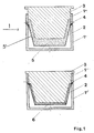
- Fig.1 Eine schematische Darstellung des Verfahrensablaufes beim Einbringen der Suspension unter Druck mit einer gleichzeitigen mechanischen Verdichtung.
- Fig.2 Eine schematische Darstellung des Verfahrensablaufes bei Herstellung der Formteile mit zweimaliger Verdichtung.
- Fig.1 A schematic representation of the process flow when introducing the suspension under pressure with a simultaneous mechanical compression.
- Fig.2 A schematic representation of the process flow in the production of the molded parts with two compression.
Die Einrichtung zur Durchführung des Verfahrens weist einen Gießkasten 1, bestehend aus einem Unterteil 1′ und Oberteil 1˝, eine mit seitlichen und bodenseitigen Perforationen versehene Außenform 2 und einen Verdichtungsstempel 3 auf. An dem Gießkasten 1 sind Zufuhrkanäle 4 für die Eingabe der Suspension vorgesehen. Es ergibt sich folgender Verfahrensablauf: Die Suspension 5 wird durch die Kanäle 4 in die Außenform 2 unter Druck eingegeben. Ist der Füllraum 5′, der durch die Wandungen der Außenform 2 und die Innenwandungen des Stempels 3 begrenzt ist, mit Suspension gefüllt, so wird der Stempel 3 abgesenkt, die Suspensionszufuhr wird unterbrochen. Gleichzeitig wird das überschüssige Wasser aus der Suspension 5 mittels Unterdruck ausgetrieben, was durch die in der Außenform 2 angebrachten Perforationen erleichtert wird. Das so hergestellte Formteil 6 wird anschließend bei erhöhter Temperatur getrocknet und wärmevergütet.The device for performing the method has a
Zur Durchführung des in Fig. 2 dargestellten Verfahrensablaufes weist die Einrichtung folgende Bestandteile auf: Einen Mischer 7, eine Dosierpumpe 8, eine in einem Gießkasten 9 angebrachte, bodenseitig und seitlich perforierte Außenform 10, einen Abscheider 11, einen Vakuumvorratsbehälter 12, eine Vakuumpumpe 13, einen Gießstempel 14, einen Preßstempel 15, eine gesonderte, perforierte Innenform 16 und einen Trockenschrank 17 auf. Der Verfahrensablauf ist folgender: Aus den Bestandteilen Wasser (A), Fasern (B), und Bindemittel (C) unter Zugabe des ausgetriebenen Wassers mit Bindemittelanteilen (D) wird eine Suspension im Mischer 7 hergestellt. Die Suspension wird in die perforierte Außenform 10 gegossen, die zwischen das Ober- und Unterteil des Gießkastens 9 eingelegt ist. Nachdem die eingege bene Suspensionsmenge für den Bodenabschnitt ausreichend ist, wird der Gießvorgang unterbrochen und die Sedimentation der Fasern abgewartet, bis kein Wasser mehr aus dem Abscheider 11 fließt. Der Gießstempel 14 wird zentrisch in die Außenform 10 eingelegt, wobei durch sein Eigengewicht und/oder einen mechanischen Druck das gegossene Faserfließ verdichtet wird. Durch diesen Vorgang wird der Formteilboden 18 hergestellt. Anschließend werden Formteilwandungen 19 durch das Gießen der Suspension in den Zwischenraum zwischen der Außenkontur des Gießstempels 14 und der Innenkontur der Außenform 10 bis zu der Höhe, wo der Gießstempel 14 die größte Breite aufweist, hergestellt. Die Sedimentation der Fasern wird abgewartet, bis kein Wasser mehr aus dem Abscheider 11 fließt. Der Gießstempel 5 wird jetzt aus der Form herausgenommen und der Preßstempel 15 eingefahren. Durch den mechanischen Druck werden ausschließlich die Wandungen 19 des Formteiles verdichtet. Sobald der Preßstempel auf dem Gießkasten 9 aufliegt, wird Vakuum angelegt und das Formteil 20 durch Anlegung von Unterdruck entwässert. Hierdurch sinken die Faserrückstellkräfte des Formteiles 20, so daß am Ende des Herstellungsvorganges kein mechanischer Druck mehr erforderlich ist. Zu diesem Zeitpunkt wird das Vakuum abgeschaltet und der Preßstempel 15 herausgenommen. Das Formteil 20 wird nochmals mittels Vakuum entwässert. Anschließend wird das Formteil 20 mit der Außenform 10 aus dem Gießkasten 9 herausgenommen und auf eine perforierte Innenform 16 aufgelegt. Die perforierte Außenform 10 kann nun zur Herstellung eines weiteren Formteiles eingesetzt werden. Auf der Innenform 16 aufgelegt, wird das Formteil 20 wärmevergütet.2, the device has the following components: a
Claims (16)
Applications Claiming Priority (4)
| Application Number | Priority Date | Filing Date | Title |
|---|---|---|---|
| DE19893922382 DE3922382A1 (en) | 1989-07-07 | 1989-07-07 | MOLDED PART WITH SPACIOUS MOLDING FROM LIGNOCELLULOSE-CONTAINING FIBERS, AND METHOD AND DEVICE FOR THE PRODUCTION THEREOF |
| DE3922382 | 1989-07-07 | ||
| DE8910860U DE8910860U1 (en) | 1989-07-07 | 1989-09-12 | Coffin for burial or cremation |
| DE8910860U | 1989-09-12 |
Publications (3)
| Publication Number | Publication Date |
|---|---|
| EP0406783A2 true EP0406783A2 (en) | 1991-01-09 |
| EP0406783A3 EP0406783A3 (en) | 1991-09-04 |
| EP0406783B1 EP0406783B1 (en) | 1995-05-24 |
Family
ID=25882763
Family Applications (1)
| Application Number | Title | Priority Date | Filing Date |
|---|---|---|---|
| EP90112631A Expired - Lifetime EP0406783B1 (en) | 1989-07-07 | 1990-07-03 | Process for making hollow articles from lignocellulosic fibres |
Country Status (3)
| Country | Link |
|---|---|
| EP (1) | EP0406783B1 (en) |
| AT (1) | ATE123094T1 (en) |
| DE (2) | DE8910860U1 (en) |
Cited By (7)
| Publication number | Priority date | Publication date | Assignee | Title |
|---|---|---|---|---|
| EP0466653A1 (en) * | 1990-07-11 | 1992-01-15 | Alois Koch | Procedure for manufacture of a coffin from formed pulp material |
| FR2711998A1 (en) * | 1993-11-04 | 1995-05-12 | Chanard Alain | Process for recycling waste paper for an ecological and economical insulating objective |
| NL1001959C2 (en) * | 1995-12-21 | 1997-06-24 | Univ Delft Tech | Processing waste flower bulb for cardboard material using adhesive |
| WO1999022069A1 (en) * | 1997-10-25 | 1999-05-06 | Px Technologies Ltd. | Method and device for forming articles from pulp slurry |
| US6210531B1 (en) | 1998-10-26 | 2001-04-03 | Px Technologies, Ltd. | Forming machines |
| EP1548189A1 (en) * | 2003-12-05 | 2005-06-29 | Sonoco Development, Inc. | Apparatus and process for forming three-dimensional fibrous panels |
| RU2270895C1 (en) * | 2004-06-15 | 2006-02-27 | Общество с ограниченной ответственностью "Научно-производственная Компания "РАНКО" | Method for manufacture of molded products from pulp |
Families Citing this family (3)
| Publication number | Priority date | Publication date | Assignee | Title |
|---|---|---|---|---|
| DE4330151A1 (en) * | 1993-09-07 | 1995-03-09 | Markus Brink | Coffin for cremations and burials made of mechanical wood pulp fibre - a material recovered from 100% recycling paper - or similar materials (cellulose), including material-related carrying technique |
| DE19508434A1 (en) * | 1995-03-09 | 1996-09-12 | Duerener Sargfabrik Jacobs Kli | Coffin made using natural fibers and process for its manufacture |
| MY137949A (en) * | 2003-08-01 | 2009-04-30 | Soon Seng Palm Products Sdn Bhd Now Known As Agro Bio Fibre Sdn Bhd | Device and manufacturing process for forming articles from plant fibre |
Family Cites Families (6)
| Publication number | Priority date | Publication date | Assignee | Title |
|---|---|---|---|---|
| GB261529A (en) * | 1925-10-19 | 1926-11-25 | Richard Ellis Hall | Improvements in or relating to the manufacture of reinforced hollow ware articles or containers made from fibrous material |
| US1623731A (en) * | 1926-04-02 | 1927-04-05 | Hutchens Edward | Pulp-forming press |
| CH183698A (en) * | 1935-07-04 | 1936-04-30 | Yngve Hedqvist Oskar | Device for the production of box-like objects from a mass which contains fibers suspended in water. |
| DE879354C (en) * | 1942-06-24 | 1953-06-11 | Norddeutsche Homogenholz Ges M | Process for the production of molded fibrous bodies |
| DE855196C (en) * | 1945-04-14 | 1952-11-10 | Norddeutsche Homogenholz Ges M | Process and device for the production of molded fibrous bodies |
| US4034447A (en) * | 1975-10-02 | 1977-07-12 | Idra Ag | Papier-mache coffin |
-
1989
- 1989-09-12 DE DE8910860U patent/DE8910860U1/en not_active Expired - Lifetime
-
1990
- 1990-07-03 DE DE59009115T patent/DE59009115D1/en not_active Expired - Fee Related
- 1990-07-03 EP EP90112631A patent/EP0406783B1/en not_active Expired - Lifetime
- 1990-07-03 AT AT90112631T patent/ATE123094T1/en active
Cited By (8)
| Publication number | Priority date | Publication date | Assignee | Title |
|---|---|---|---|---|
| EP0466653A1 (en) * | 1990-07-11 | 1992-01-15 | Alois Koch | Procedure for manufacture of a coffin from formed pulp material |
| FR2711998A1 (en) * | 1993-11-04 | 1995-05-12 | Chanard Alain | Process for recycling waste paper for an ecological and economical insulating objective |
| NL1001959C2 (en) * | 1995-12-21 | 1997-06-24 | Univ Delft Tech | Processing waste flower bulb for cardboard material using adhesive |
| WO1999022069A1 (en) * | 1997-10-25 | 1999-05-06 | Px Technologies Ltd. | Method and device for forming articles from pulp slurry |
| US6210531B1 (en) | 1998-10-26 | 2001-04-03 | Px Technologies, Ltd. | Forming machines |
| EP1548189A1 (en) * | 2003-12-05 | 2005-06-29 | Sonoco Development, Inc. | Apparatus and process for forming three-dimensional fibrous panels |
| US7074302B2 (en) | 2003-12-05 | 2006-07-11 | Sonoco Development, Inc. | Apparatus and process for forming three-dimensional fibrous panels |
| RU2270895C1 (en) * | 2004-06-15 | 2006-02-27 | Общество с ограниченной ответственностью "Научно-производственная Компания "РАНКО" | Method for manufacture of molded products from pulp |
Also Published As
| Publication number | Publication date |
|---|---|
| EP0406783A3 (en) | 1991-09-04 |
| DE59009115D1 (en) | 1995-06-29 |
| DE8910860U1 (en) | 1990-11-08 |
| EP0406783B1 (en) | 1995-05-24 |
| ATE123094T1 (en) | 1995-06-15 |
Similar Documents
| Publication | Publication Date | Title |
|---|---|---|
| AT398934B (en) | METHOD AND DEVICE FOR PRODUCING BLOCKS FROM ANY MATERIAL AND BLOCKS AS AN IMMEDIATE PRODUCT OF THIS METHOD | |
| DE3233241A1 (en) | METHOD FOR PRESSING MOLDED PARTS FROM BINDER-CONTAINING ORGANIC FIBER MATS AND DEVICE FOR IMPLEMENTING THE METHOD | |
| EP0048367A1 (en) | Pallet-support and method of producing the same | |
| EP0406783B1 (en) | Process for making hollow articles from lignocellulosic fibres | |
| DE3936904A1 (en) | METHOD FOR PRODUCING ALSO LARGE-SIDED PANELS FROM CERAMIC MATERIAL WITH INCREASED MECHANICAL PROPERTIES | |
| EP0466653B1 (en) | Procedure for manufacture of a coffin from formed pulp material | |
| CH346362A (en) | Device for pressing hollow bodies | |
| DE1752695C3 (en) | Process for producing tablets from a pulp and apparatus for carrying out the process | |
| DE3922382C2 (en) | ||
| DE19622001A1 (en) | System for manufacturing concrete blocks | |
| DE19540189A1 (en) | Press for fibre and plastic composites e.g. for car body panels | |
| EP0115552B1 (en) | Apparatus for manufacturing moulded articles | |
| EP1605101B1 (en) | Process and apparatus for the fabrication of a multilayered concrete plate | |
| EP0130359B1 (en) | Method of manufacturing cross-bars, sections, beams or the like of compressed small size vegetal parts | |
| DE10314974B4 (en) | Process for the production of moldings with a coherent lignocellulose-containing fibers having shaping structure and moldings | |
| DE2909526A1 (en) | PROCESS FOR CREATING HOLES IN BODIES FROM MOLDABLE CHIPPINGS OR DGL. AND DEVICE FOR CARRYING OUT THE PROCEDURE | |
| EP0084074B1 (en) | Method of manufacturing pressed shaped articles of a non-expandable composition | |
| DE2621717C2 (en) | Device for the metered filling of stationary molds | |
| DE288292C (en) | Method and device for producing moldings from cement raw material by semi-dry pressing. | |
| DE2443837A1 (en) | PROCESS FOR MANUFACTURING COMPRESSED BODIES, IN PARTICULAR LIMESTONE SAND STONES AND DEVICE FOR CARRYING OUT THE PROCESS | |
| DE2804754C2 (en) | Process for the production of molded bodies from concrete | |
| DE4342789C2 (en) | Process for the production of molded parts | |
| DE2618599A1 (en) | Perforated vibrating container - for preloading particulate moulding materials to automate control of wall thickness and/or density | |
| EP0184551B1 (en) | Apparatus for making gypsum building plates by the dry process | |
| AT358974B (en) | METHOD AND DEVICE FOR PRODUCING MOLDED BODIES |
Legal Events
| Date | Code | Title | Description |
|---|---|---|---|
| PUAI | Public reference made under article 153(3) epc to a published international application that has entered the european phase |
Free format text: ORIGINAL CODE: 0009012 |
|
| AK | Designated contracting states |
Kind code of ref document: A2 Designated state(s): AT BE CH DE DK ES FR GB GR IT LI LU NL SE |
|
| PUAL | Search report despatched |
Free format text: ORIGINAL CODE: 0009013 |
|
| AK | Designated contracting states |
Kind code of ref document: A3 Designated state(s): AT BE CH DE DK ES FR GB GR IT LI LU NL SE |
|
| 17P | Request for examination filed |
Effective date: 19920302 |
|
| 17Q | First examination report despatched |
Effective date: 19931018 |
|
| GRAA | (expected) grant |
Free format text: ORIGINAL CODE: 0009210 |
|
| AK | Designated contracting states |
Kind code of ref document: B1 Designated state(s): AT BE CH DE DK ES FR GB GR IT LI LU NL SE |
|
| PG25 | Lapsed in a contracting state [announced via postgrant information from national office to epo] |
Ref country code: IT Free format text: LAPSE BECAUSE OF FAILURE TO SUBMIT A TRANSLATION OF THE DESCRIPTION OR TO PAY THE FEE WITHIN THE PRESCRIBED TIME-LIMIT;WARNING: LAPSES OF ITALIAN PATENTS WITH EFFECTIVE DATE BEFORE 2007 MAY HAVE OCCURRED AT ANY TIME BEFORE 2007. THE CORRECT EFFECTIVE DATE MAY BE DIFFERENT FROM THE ONE RECORDED. Effective date: 19950524 Ref country code: GR Free format text: LAPSE BECAUSE OF FAILURE TO SUBMIT A TRANSLATION OF THE DESCRIPTION OR TO PAY THE FEE WITHIN THE PRESCRIBED TIME-LIMIT Effective date: 19950524 Ref country code: NL Free format text: LAPSE BECAUSE OF FAILURE TO SUBMIT A TRANSLATION OF THE DESCRIPTION OR TO PAY THE FEE WITHIN THE PRESCRIBED TIME-LIMIT Effective date: 19950524 Ref country code: GB Effective date: 19950524 Ref country code: DK Effective date: 19950524 Ref country code: ES Free format text: THE PATENT HAS BEEN ANNULLED BY A DECISION OF A NATIONAL AUTHORITY Effective date: 19950524 |
|
| REF | Corresponds to: |
Ref document number: 123094 Country of ref document: AT Date of ref document: 19950615 Kind code of ref document: T |
|
| ET | Fr: translation filed | ||
| REF | Corresponds to: |
Ref document number: 59009115 Country of ref document: DE Date of ref document: 19950629 |
|
| PG25 | Lapsed in a contracting state [announced via postgrant information from national office to epo] |
Ref country code: LU Free format text: LAPSE BECAUSE OF NON-PAYMENT OF DUE FEES Effective date: 19950731 |
|
| NLV1 | Nl: lapsed or annulled due to failure to fulfill the requirements of art. 29p and 29m of the patents act | ||
| GBV | Gb: ep patent (uk) treated as always having been void in accordance with gb section 77(7)/1977 [no translation filed] |
Effective date: 19950524 |
|
| PLBE | No opposition filed within time limit |
Free format text: ORIGINAL CODE: 0009261 |
|
| STAA | Information on the status of an ep patent application or granted ep patent |
Free format text: STATUS: NO OPPOSITION FILED WITHIN TIME LIMIT |
|
| 26N | No opposition filed | ||
| PGFP | Annual fee paid to national office [announced via postgrant information from national office to epo] |
Ref country code: FR Payment date: 19960716 Year of fee payment: 7 |
|
| PGFP | Annual fee paid to national office [announced via postgrant information from national office to epo] |
Ref country code: DE Payment date: 19960717 Year of fee payment: 7 |
|
| PGFP | Annual fee paid to national office [announced via postgrant information from national office to epo] |
Ref country code: AT Payment date: 19960719 Year of fee payment: 7 Ref country code: BE Payment date: 19960719 Year of fee payment: 7 Ref country code: SE Payment date: 19960719 Year of fee payment: 7 |
|
| PGFP | Annual fee paid to national office [announced via postgrant information from national office to epo] |
Ref country code: CH Payment date: 19960722 Year of fee payment: 7 |
|
| PG25 | Lapsed in a contracting state [announced via postgrant information from national office to epo] |
Ref country code: AT Free format text: LAPSE BECAUSE OF NON-PAYMENT OF DUE FEES Effective date: 19970703 |
|
| PG25 | Lapsed in a contracting state [announced via postgrant information from national office to epo] |
Ref country code: SE Effective date: 19970704 |
|
| PG25 | Lapsed in a contracting state [announced via postgrant information from national office to epo] |
Ref country code: BE Free format text: LAPSE BECAUSE OF NON-PAYMENT OF DUE FEES Effective date: 19970731 Ref country code: CH Free format text: LAPSE BECAUSE OF NON-PAYMENT OF DUE FEES Effective date: 19970731 Ref country code: LI Free format text: LAPSE BECAUSE OF NON-PAYMENT OF DUE FEES Effective date: 19970731 |
|
| BERE | Be: lapsed |
Owner name: FRAUNHOFER-GESELLSCHAFT ZUR FORDERUNG DER ANGEWAN Effective date: 19970731 |
|
| REG | Reference to a national code |
Ref country code: CH Ref legal event code: PL |
|
| PG25 | Lapsed in a contracting state [announced via postgrant information from national office to epo] |
Ref country code: FR Free format text: LAPSE BECAUSE OF NON-PAYMENT OF DUE FEES Effective date: 19980331 |
|
| PG25 | Lapsed in a contracting state [announced via postgrant information from national office to epo] |
Ref country code: DE Free format text: LAPSE BECAUSE OF NON-PAYMENT OF DUE FEES Effective date: 19980401 |
|
| EUG | Se: european patent has lapsed |
Ref document number: 90112631.8 |
|
| REG | Reference to a national code |
Ref country code: FR Ref legal event code: ST |