EP0406507B1 - Blockkodierungsschema für die Übertragung von partiellen Bits - Google Patents
Blockkodierungsschema für die Übertragung von partiellen Bits Download PDFInfo
- Publication number
- EP0406507B1 EP0406507B1 EP89810516A EP89810516A EP0406507B1 EP 0406507 B1 EP0406507 B1 EP 0406507B1 EP 89810516 A EP89810516 A EP 89810516A EP 89810516 A EP89810516 A EP 89810516A EP 0406507 B1 EP0406507 B1 EP 0406507B1
- Authority
- EP
- European Patent Office
- Prior art keywords
- bits
- symbol
- symbols
- bit
- block
- Prior art date
- Legal status (The legal status is an assumption and is not a legal conclusion. Google has not performed a legal analysis and makes no representation as to the accuracy of the status listed.)
- Expired - Lifetime
Links
- 230000005540 biological transmission Effects 0.000 title description 16
- 238000000034 method Methods 0.000 claims description 26
- 239000000872 buffer Substances 0.000 claims description 12
- 238000013507 mapping Methods 0.000 description 7
- 230000011664 signaling Effects 0.000 description 5
- 238000010586 diagram Methods 0.000 description 2
- 230000006870 function Effects 0.000 description 2
- 230000006978 adaptation Effects 0.000 description 1
- 230000001419 dependent effect Effects 0.000 description 1
Images


Classifications
-
- H—ELECTRICITY
- H04—ELECTRIC COMMUNICATION TECHNIQUE
- H04L—TRANSMISSION OF DIGITAL INFORMATION, e.g. TELEGRAPHIC COMMUNICATION
- H04L27/00—Modulated-carrier systems
- H04L27/32—Carrier systems characterised by combinations of two or more of the types covered by groups H04L27/02, H04L27/10, H04L27/18 or H04L27/26
- H04L27/34—Amplitude- and phase-modulated carrier systems, e.g. quadrature-amplitude modulated carrier systems
- H04L27/3405—Modifications of the signal space to increase the efficiency of transmission, e.g. reduction of the bit error rate, bandwidth, or average power
- H04L27/3416—Modifications of the signal space to increase the efficiency of transmission, e.g. reduction of the bit error rate, bandwidth, or average power in which the information is carried by both the individual signal points and the subset to which the individual points belong, e.g. using coset coding, lattice coding, or related schemes
- H04L27/3427—Modifications of the signal space to increase the efficiency of transmission, e.g. reduction of the bit error rate, bandwidth, or average power in which the information is carried by both the individual signal points and the subset to which the individual points belong, e.g. using coset coding, lattice coding, or related schemes in which the constellation is the n - fold Cartesian product of a single underlying two-dimensional constellation
- H04L27/3433—Modifications of the signal space to increase the efficiency of transmission, e.g. reduction of the bit error rate, bandwidth, or average power in which the information is carried by both the individual signal points and the subset to which the individual points belong, e.g. using coset coding, lattice coding, or related schemes in which the constellation is the n - fold Cartesian product of a single underlying two-dimensional constellation using an underlying square constellation
-
- H—ELECTRICITY
- H04—ELECTRIC COMMUNICATION TECHNIQUE
- H04L—TRANSMISSION OF DIGITAL INFORMATION, e.g. TELEGRAPHIC COMMUNICATION
- H04L27/00—Modulated-carrier systems
- H04L27/32—Carrier systems characterised by combinations of two or more of the types covered by groups H04L27/02, H04L27/10, H04L27/18 or H04L27/26
- H04L27/34—Amplitude- and phase-modulated carrier systems, e.g. quadrature-amplitude modulated carrier systems
- H04L27/345—Modifications of the signal space to allow the transmission of additional information
- H04L27/3461—Modifications of the signal space to allow the transmission of additional information in order to transmit a subchannel
- H04L27/3477—Modifications of the signal space to allow the transmission of additional information in order to transmit a subchannel by using the outer points of the constellation or of the constituent two-dimensional constellations
Definitions
- Present invention is concerned with coding of data for transmission using trellis-coded modulation, and in particular with a method and apparatus for converting a bit stream representing data into symbols of an expanded two-dimensional symbol set. Each of these symbols is to be used for modulating a carrier to assume a discrete signal value.
- EPA-A-0 122 805 additionally describes the use of non-integer block lengths in coded systems.
- a further object of the invention is a TCM transmission system with a non-integer number of bits per symbol, which allows to combine in the reciever the functions of equalizing and trellis decoding.
- Another object of the invention is to provide a coding scheme for TCM transmission allowing the transmission of a fractional bit number per symbol, which is simple in design.
- the invention achieves the objects mainly by providing a particular combination of trellis encoding on blocks of data bits, and by expanding and block encoding a portion of each block to obtain the selection of symbols from particular symbol subsets.
- An advantage of present invention is that it allows to transmit any fractional number of bits per symbol and thus to freely select any desired data rate (bit rate) for a given symbol rate (Baud rate).
- a further advantage is that with the novel coding scheme, it is possible to make decisons on single symbols for receiver adaptation thus preventing the necessity of waiting for the end of a whole group of symbols to make a decision, which introduces an undesirable delay.
- Another advantage of the invention is that it can be used in systems applying combined equalization and trellis decoding, which results in enhanced performance in the presence of intersymbol interference.
- a further advantage is that the coding technique is designed for two-dimensional trellis-coded systems so that no complicated procedures and circuits need be used which are required for multi-dimensional TCM schemes.
- the coding scheme is also well suited for digital radio and satellite transmission sytems.
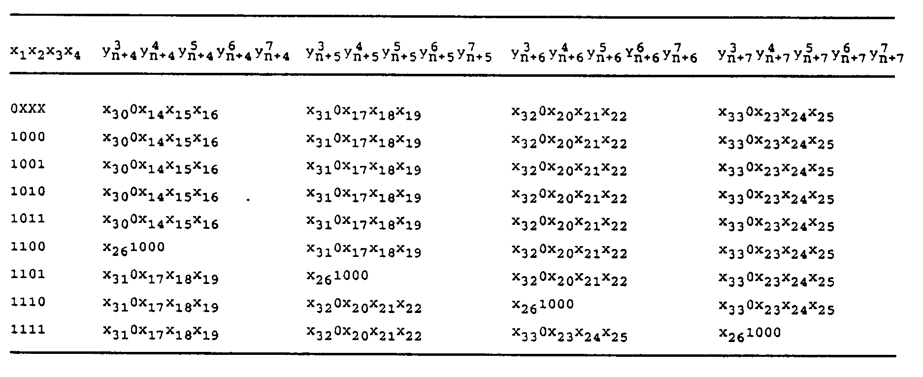
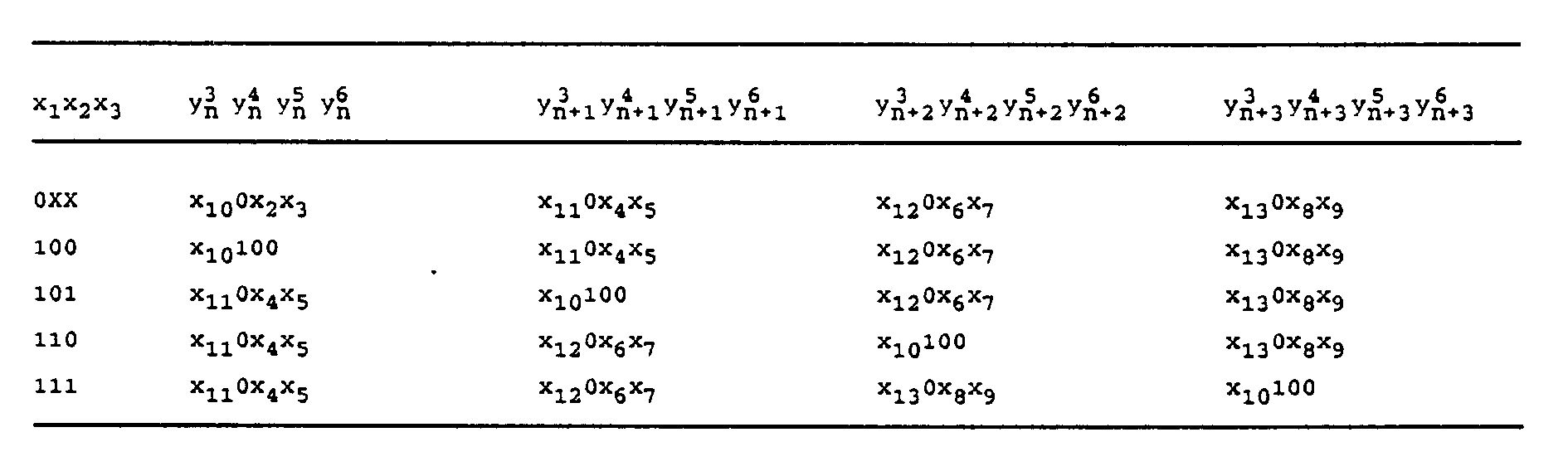
- Table 1 (consisting of partial tables 1A and 1B) shows the mapping of input bits to output bits in the block encoder used in the example of Fig.2; and Table 2 shows the mapping of input bits to output bits in the block encoder used in the example of Fig.3.
- the incoming bit stream is grouped into blocks, and each block will be represented by a fixed number w of symbols.
- a first portion (s) of each block is used to specify sequentially the w different subsets from which the w symbols are to be taken.
- Trellis encoding is employed for this portion to thus achieve the advantages of single-symbol Trellis-Coded Modulation (TCM) which are already known from previous systems.
- TCM Trellis-Coded Modulation
- the second portion (r) of each block is used to select, in w successive intervals, from each of the w subsets specified by the first portion, one specific symbol.
- the remaining (m - m')2 k + 1 information bits determine which symbols from the sequence of 2 k subsets are to be transmitted.
- One bit in the remaining block of (m - m')2 k + 1 information bits determines whether some outer symbol from the chosen 2 k successive subsets is to be transmitted. If not, then the (m - m')2 k bits are used, m - m' at a time, to select 2 k inner subset points.
- X designates input bits of a stored bit block
- Z designates intermediate bits which are either fed into the convolutional encoder for subset specification, or directly used for symbol selection (cf. designations X and Z in Figs.2 and 3).
- estimated bits " ⁇ " delivered by a TCM decoder are mapped into estimated bits " X ⁇ " by performing the inverse of the procedure described above.
- a symbol selector 14 at the output of the coding system selects, in response to the signals on input lines 15 and 16, (which signals are derived from the contents of buffer 13), eight symbols in eight successive time intervals.
- a scanner 18 scans outputs 17 so that in each successive time interval, two bits appear on lines 19. These are provided to a convolutional rate 2/3 encoder 20 which provides in each time interval an expanded group of three bits on lines 15. This three-bit combination specifies, in selector 14, one of the eight symbol subsets.
- the convolutional encoder can be of any design.
- One example is shown in Fig.5 of U.S.Patent 4,077,021.
- Other examples are given in the above-mentioned publication by G.Ungerboeck.
- a second portion r (33 bits) of the bits stored in the buffer is furnished on lines 21 to a block coder 22.
- This is a rate 33/40 coder, i.e. it provides 40 output bits for each group of 33 input bits.
- Block coder 22 implements the procedure steps shown in the bottom of Fig.1; a specific example will be shown and explained with reference to Fig.4 and Table 1.
- the selected symbols are furnished from selector 14 to a sampler 26 which provides 2'743 symbols per second on output lines 27. These are used for modulating a carrier signal.
- Block coder 22A implements the procedure steps shown in the bottom of Fig.1; a specific example will be shown and explained later with reference to Fig.5 and Table 2.
- Fig.4 depicts the 144-symbol set used for the coding system shown in Fig.2.
- the eight symbol subsets into which the whole set is subdivided are designated by letters A through H.
- each position (point) shows by a respective letter to which subset the particular symbol located there belongs.
- Some of the symbols are outer symbols, and they are designated by A', B', etc.
- each subset comprises eighteen symbols, of which sixteen are inner symbols and two are outer symbols.
- the individual identification or address of each symbol in the whole set is given by an 8-bit label (y 0 n , y 1 n , y 2 n , y 3 n , y 4 n , y 5 n , y 6 n , y 7 n ) , as will be shown in the next section.
- the inner group of the constellation consists of 128 points, whereas the outer group consists of sixteen points which is only one eighth of the inner group.
- Fig.5 depicts the 80-symbol set used for the example of Fig.3. Subdivision into eight subsets, each of which has two outer symbols, is similar as explained above with respect to the 144-symbol case. Thus, each subset in the case of Fig.5 comprises ten symbols, of which eight are inner and two are outer symbols. Identification of each individual symbol is achieved by a 7-bit label (y 0 n , y 1 n , y 2 n , y 3 n , y 4 n , y 5 n , y 6 n ) , as will be shown in more detail in the next section.
- the inner group of this constellation consists of 64 points, whereas the outer group consists of sixteen points which is only one quarter of the inner group.
- the first three bits of the labels designate the subset (i.e. all symbols of the A-set have an identical group of three first bits in the label); the remaining label bits distinguish points within the subset.
- the five bits (y 3 n , y 4 n , y 5 n , y 6 n , y 7 n ) representing the subset-internal label would be X1000 for the two outer symbols and X0XXX for the sixteen inner symbols.
- a block coder is used for converting a portion r of each bit block to an expanded bit group which consists of w different q-bit subgroups, each for selecting one particular symbol of a specified symbol subset.
- This encoder implements the steps shown at the bottom of Figure 1, i.e. using one bit of the portion r for determining whether an outer symbol is to be selected, and using the other bits to determine which (if any) of the w symbols is to be the outer symbol, and further for selecting in each of the w time intervals one specific (inner or outer) symbol.
- mapping of input bits to output bits in this block encoder i.e. the particular selection of symbols, is important for an efficient coding procedure. Therefore, two particularly suitable bit mapping examples for the block coder, one for the case of Fig.2 and another one for that of Fig.3, have been drafted. They are shown in Table 1 and Table 2, respectively.
- Table 1 shows the bit mapping for the block coder 22 of Fig.2, i.e. for the case where 33 bits of the current bit block (portion r) are expanded into 40 bits which constitute eight different bit subgroups each consisting of five bits (for selecting one particular symbol out of eighteen symbols of a symbol subset).
- each 49-bit block is designated as x1, x2, ... , x49 .
- the set of eight 8-bit labels 1 0,1,2,3,4,5,6,7 thus selects eight unique members of the 144-point signal constellation which are transmitted over the channel in accordance to the coding rules of single-symbol TCM.
- Table 2 shows the bit mapping for the block coder 22A of Fig.3, i.e. for the case where 13 bits of the current bit block (portion r) are expanded into sixteen bits which constitute four different bit subgroups each consisting of four bits (for selecting one particular symbol out of ten symbols of a symbol subset).
- bits of each 21-bit block are designated as x1, x2, ... , x21 .
- the block coding scheme of present invention has proven to be very useful in combination with a receiver design in which the functions of equalization and trellis decoding are combined.
- a receiver design in which the functions of equalization and trellis decoding are combined.
- Such a receiver has been described in a paper by P.R.Chevillat and E.Eleftheriou "Decoding of Trellis-Encoded Signals in the Presence of Intersymbol Interference and Noise", IEEE Conference Record, ICC'88, June 1988, pp.694-699.
Landscapes
- Engineering & Computer Science (AREA)
- Computer Networks & Wireless Communication (AREA)
- Signal Processing (AREA)
- Error Detection And Correction (AREA)
- Compression, Expansion, Code Conversion, And Decoders (AREA)
Claims (11)
- Verfahren zur Codierung von Daten durch Konvertieren einer die Daten repräsentierenden Bitfolge in Symbole eines erweiterten zweidimensionalen Symbolsatzes, wobei jedes Symbol einen diskreten Wert aus einer begrenzten Anzahl diskreter Werte repräsentiert und das Verfahren folgende Schritte umfaßt:- Unterteilen des Symbolsatzes in eine Vielzahl disjunkter Symbol-Teilsätze, von denen jeder eine Anzahl Symbole enthält, die nicht als ganzzahlige Potenz zur Basis Zwei dargestellt werden kann und wobei jeder Symbol-Teilsatz äußere Symbole, die an der Peripherie des Symbolsatzes lokalisiert sind sowie innere Symbole umfaßt;- Aufspalten der Datenbitfolge in Blöcke fester Länge, wobei jeder Block eine Anzahl Bits enthält, die kein ganzzahliges Vielfaches einer vorgegebenen Zahl m ist und ein jeder solcher Block durch w besagte Symbole repräsentiert wird; und daßdas Verfahren weiterhin durch folgende Schritte gekennzeichnet wird:- Erweiterung jeder der w einzelnen p-Bit-Untergruppen, die aus einem ersten Teil (s) jedes Blockes abgeleitet werden, durch Trellis-Codierung und Verwendung jeder erweiterten Bitgruppe zur Spezifikation einer der t Symbol-Teilsätze;- Blockcodierung, einschließlich Erweiterung, des verbleibenden zweiten Teiles (r) jedes Blockes zur Ableitung von w separaten q-Bit-Untergruppen, wobei durch jede eines der Symbole, die in dem Symbolsatz spezifiziert sind, ausgewählt wird; und- weniger häufige Auswahl der äußeren Symbole im Vergleich zu den inneren Symbolen.
- Vorrichtung zur Codierung von Daten durch Konvertieren einer die Daten repräsentierenden Bitfolge in Symbole eines erweiterten zweidimensionalen Symbolsatzes, wobei jedes Symbol einen diskreten Wert aus einer begrenzten Anzahl diskreter Werte repräsentiert und die Vorrichtung folgende Elemente umfaßt:- Pufferspeichermittel (13) zum Empfangen eines Bitblockes des zu codierenden Datenstromes, wobei die vorgegebene Bitzahl des Blockes kein ganzzahliges Vielfaches einer vorgegebenen Zahl m ist;und diese Vorrichtung weiterhin durch folgende Elemente gekennzeichnet ist:- Symbolauswahlmittel (14) zur Auswahl eines Symbols aus dem erweiterten zweidimensionalen Symbolsatz in Abhängigkeit von zwei Bitgruppen, die an zwei Gruppen Eingänge des Symbolauswahlmittels angelegt werden, wobei eine Bitgruppe an eine erste Gruppe (15) Eingänge angelegt wird, die eine der t disjunkten Symbol-Teilsätze spezifizieren, von denen jeder eine Anzahl Symbole enthält, die nicht als ganzzahlige Potenz zur Basis Zwei dargestellt werden kann und wobei die andere Bitgruppe an eine zweite Gruppe (16) Eingänge angelegt wird, die ein spezielles Symbol aus dem spezifizierten Symbol-Teilsatz auswählen;- erste Abtastmittel (18) zur Auswahl eines jeden der w separaten p-Bit-Untergruppen des ersten Teiles (17, s) der im Pufferspeichermittel gespeicherten Bits in aufeinanderfolgenden Zeitabsschnitten;- Faltungs-Codiermittel (20), welche die Bits jeder p-Bit-Untergruppe (19) empfangen, die von dem ersten Abtastmittel ausgewählt wurde und die weiterhin an ihrem Ausgang eine entsprechende erweiterte Bitgruppe für die erste Gruppe Eingänge des Symbolauswahlmittels bereitstellen;- Blockcodiermittel (22), die mit den Pufferspeichermitteln verbunden sind, um einen zweiten Teil (21, r) der im Pufferspeichermittel gespeicherten Bits zu empfangen und die eine daraus sich ergebende erweiterte Bitgruppe (23) in w separaten q-Bit-Untergruppen an ihrem Ausgang bereitstellen und- zweite Abtastmittel (24), die in aufeinanderfolgenden Zeitabschnitten jede der vom Blockcodiermittel ausgegebenen w separaten q-Bit-Untergruppen auswählen und die entsprechende Bit-Untergruppe (25) an der zweiten Gruppe der Eingänge der Symbolauswahlmittel bereitstellen.
- Verfahren nach Anspruch 1, dadurch gekennzeichnet, daß Daten durch Symbole aus einem 144 Symbole umfassenden Symbolsatz codiert werden, der in acht Teilsätze unterteilt ist, wobei bei diesem Verfahren
jeder dieser Blöcke 49 Bits umfaßt und durch w = 8 Symbole repräsentiert wird, dabei der erste Teil (s) 16 Bits umfaßt und der zweite Teil (r) 33 Bits umfaßt, der Trellis-Codierschritt eine Bitraten-Erweiterung von 2/3 bewirkt und der Blockcodierschritt eine Bitraten-Erweiterung von 33/40 bewirkt. - Verfahren nach Anspruch 3, dadurch gekennzeichnet, daß
innerhalb des Blockcodierschrittes acht Bezeichner erzeugt werden, wobei jeder Bezeichner fünf Bits umfaßt, um ein Symbol aus einem der 18 Symbole umfassenden Teilsätze auszuwählen, die jeweils 16 innere Symbole und zwei äußere Symbole enthalten, einer dieser Bezeichner ein äußeres Symbol auswählt und die verbleibenden Bezeichner innere Symbole auswählen. - Verfahren nach Anspruch 1, dadurch gekennzeichnet, daß Daten durch Symbole aus einem 80 Symbole umfassenden Symbolsatz codiert werden, der in acht Teilsätze unterteilt ist, wobei bei diesem Verfahren jeder dieser Blöcke 21 Bits umfaßt und durch w = 4 Symbole repräsentiert wird, dabei der erste Teil (s) acht Bits umfaßt und der zweite Teil (r) dreizehn Bits umfaßt, der Trellis-Codierschritt eine Bitraten-Erweiterung von 2/3 bewirkt und der Blockcodierschritt eine Bitraten-Erweiterung von 13/16 bewirkt.
- Verfahren nach Anspruch 5, dadurch gekennzeichnet, daß
innerhalb des Blockcodierschrittes vier Bezeichner erzeugt werden, wobei jeder Bezeichner fünf Bits umfaßt, um ein Symbol aus einem der 10 Symbole umfassenden Teilsätze auszuwählen, die jeweils acht innere Symbole und zwei äußere Symbole enthalten, einer dieser Bezeichner ein äußeres Symbol auswählt und die verbleibenden Bezeichner innere Symbole auswählen. - Verfahren gemäß Anspruch 1, dadurch gekennzeichnet, daß der Blockcodierschritt umfaßt:
Codieren des zweiten Teiles (r) zur Erzeugung von w separaten q-Bit-Untergruppen, so daß eine Untergruppe ein äußeres Symbol und (w-1) Untergruppen innere Symbole aus einem spezifizierten Teilsatz auswählen. - Vorrichtung nach Anspruch 2, dadurch gekennzeichnet,
daß- die Pufferspeichermittel (13) eine Kapazität zum Speichern von jeweils 49 Bits umfassen;- die Symbolauswahlmittel (14) ein Alphabet von 144 Symbolen, unterteilt in t = 8 Teilsätze, bereitstellen;- die ersten Abtastmittel (18) acht separate Bitgruppen von je zwei Bit auswählen, jede aus einem ersten Teil (s), der sechzehn Bits umfaßt;- die Faltungs-Codiermittel (20) eine Bitraten-Erweiterung von 2/3 bewirken; und daß- die Blockcodiermittel (22) einen zweiten Teil (r) empfangen, der 33 Bits umfaßt, um diesen auf acht Gruppen zu je fünf Bits zu erweitern. - Vorrichtung nach Anspruch 8, dadurch gekennzeichnet, daß die Blockcodiermittel (22) einen zweiten Teil (r) empfangen der 33 Bits umfaßt (X₁, X₂, ... , X₃₃) und der acht Ausgangs-Bitgruppen zu je fünf Bits


- Vorrichtung nach Anspruch 2, dadurch gekennzeichnet,
daß- die Pufferspeichermittel (13A) eine Kapazität zum Speichern von jeweils 21 Bits umfassen;- die Symbolauswahlmittel (14A) ein Alphabet von 80 Symbolen, unterteilt in t = 8 Teilsätze, bereitstellen;- die ersten Abtastmittel (18A) vier separate Bitgruppen von je zwei Bit auswählen, jede aus einem ersten Teil (s), der acht Bits umfassen;- die Faltungs-Codiermittel (20) eine Bitraten-Erweiterung von 2/3 bewirkten und daß- die Blockcodiermittel (22A) einen zweiten Teil (r) empfangen, der 13 Bits umfaßt, um diesen auf vier Gruppen zu je vier Bits zu erweitern. - Vorrichtung nach Anspruch 10, dadurch gekennzeichnet, daß die Blockcodiermittel (22A) einen zweiten Teil (r) empfangen, der 13 Bits umfaßt (X₁, X₂, ... , X₁₃) und der acht Ausgangs-Bitgruppen zu je fünf Bits


Priority Applications (4)
| Application Number | Priority Date | Filing Date | Title |
|---|---|---|---|
| EP89810516A EP0406507B1 (de) | 1989-07-07 | 1989-07-07 | Blockkodierungsschema für die Übertragung von partiellen Bits |
| DE68915758T DE68915758T2 (de) | 1989-07-07 | 1989-07-07 | Blockkodierungsschema für die Übertragung von partiellen Bits. |
| US07/400,415 US5113401A (en) | 1989-07-07 | 1989-08-30 | Block coding scheme for fractional-bit transmission |
| JP2177641A JPH0691470B2 (ja) | 1989-07-07 | 1990-07-06 | ブロック・コード化方法 |
Applications Claiming Priority (1)
| Application Number | Priority Date | Filing Date | Title |
|---|---|---|---|
| EP89810516A EP0406507B1 (de) | 1989-07-07 | 1989-07-07 | Blockkodierungsschema für die Übertragung von partiellen Bits |
Publications (2)
| Publication Number | Publication Date |
|---|---|
| EP0406507A1 EP0406507A1 (de) | 1991-01-09 |
| EP0406507B1 true EP0406507B1 (de) | 1994-06-01 |
Family
ID=8203163
Family Applications (1)
| Application Number | Title | Priority Date | Filing Date |
|---|---|---|---|
| EP89810516A Expired - Lifetime EP0406507B1 (de) | 1989-07-07 | 1989-07-07 | Blockkodierungsschema für die Übertragung von partiellen Bits |
Country Status (4)
| Country | Link |
|---|---|
| US (1) | US5113401A (de) |
| EP (1) | EP0406507B1 (de) |
| JP (1) | JPH0691470B2 (de) |
| DE (1) | DE68915758T2 (de) |
Families Citing this family (25)
| Publication number | Priority date | Publication date | Assignee | Title |
|---|---|---|---|---|
| US4941154A (en) * | 1989-05-30 | 1990-07-10 | At&T Bell Laboratories | Trellis coding method and arrangement for fractional bit rates |
| FR2664111A1 (fr) * | 1990-06-28 | 1992-01-03 | Alcatel Transmission | Circuit de decodage de codes convolutionnels pour l'execution de l'etape de stockage et d'exploration inverse des chemins survivants d'un algorithme de viterbi. |
| GB9016420D0 (en) * | 1990-07-26 | 1990-09-12 | British Telecomm | Block coded modulation |
| EP0577670A1 (de) | 1991-03-28 | 1994-01-12 | BRITISH TELECOMMUNICATIONS public limited company | Rahmensynchronisierung für QAM |
| WO1992017971A1 (en) * | 1991-03-28 | 1992-10-15 | British Telecommunications Public Limited Company | Tcm scheme with fractional bit rates, framing signals and constellation shaping |
| US5349589A (en) * | 1991-07-01 | 1994-09-20 | Ericsson Ge Mobile Communications Inc. | Generalized viterbi algorithm with tail-biting |
| US5343500A (en) * | 1991-09-03 | 1994-08-30 | At&T Bell Laboratories | Non-linear encoder and decoder for information transmission through non-linear channels |
| US5216694A (en) * | 1991-09-12 | 1993-06-01 | At&T Bell Laboratories | Trellis coding for fractional bits |
| US5377194A (en) * | 1991-12-16 | 1994-12-27 | At&T Corp. | Multiplexed coded modulation with unequal error protection |
| EP0556854B1 (de) * | 1992-02-20 | 1996-09-11 | Mitsubishi Jidosha Kogyo Kabushiki Kaisha | Abgasemissionsregeleinrichtung |
| US5258987A (en) * | 1992-04-16 | 1993-11-02 | At&T Bell Laboratories | Multilevel coding using trellis-coded modulation and reed-solomon codes |
| US5329551A (en) * | 1992-04-16 | 1994-07-12 | At&T Bell Laboratories | Overlapped multilevel codes |
| US5408502A (en) * | 1992-07-13 | 1995-04-18 | General Instrument Corporation | Apparatus and method for communicating digital data using trellis coded QAM with punctured convolutional codes |
| CN1138379C (zh) * | 1993-12-29 | 2004-02-11 | 齐尼思电子公司 | 格式化数据帧的方法和装置 |
| CA2157958C (en) * | 1994-10-11 | 2000-01-18 | Lee-Fang Wei | Trellis coded modulation employing lower dimensionality convolutional encoder |
| US5675590A (en) | 1994-11-23 | 1997-10-07 | At&T Wireless Services, Inc. | Cyclic trellis coded modulation |
| US6889356B1 (en) | 1994-11-23 | 2005-05-03 | Cingular Wireless Ii, Llc | Cyclic trellis coded modulation |
| US5659578A (en) * | 1994-11-23 | 1997-08-19 | At&T Wireless Services, Inc. | High rate Reed-Solomon concatenated trellis coded 16 star QAM system for transmission of data over cellular mobile radio |
| US5703911A (en) * | 1995-08-17 | 1997-12-30 | Chung-Chin Chen | Decoding method for trellis codes with large free distances |
| US5996104A (en) * | 1996-09-13 | 1999-11-30 | Herzberg; Hanan | System for coding system |
| US5812601A (en) * | 1996-11-15 | 1998-09-22 | Telefonaktiebolaget Lm Ericsson | Coding for higher-level modulation |
| US6275966B1 (en) * | 1998-06-03 | 2001-08-14 | Ericsson, Inc. | Error detection for radio transmission including logically combined pseudo-random numbers and related transmitters, receivers, and methods |
| US6519737B1 (en) | 2000-03-07 | 2003-02-11 | International Business Machines Corporation | Computing the CRC bits at a time for data whose length in bits is not a multiple of M |
| WO2011021673A1 (ja) | 2009-08-19 | 2011-02-24 | 相田化学工業株式会社 | 木目金模様を備える装飾金属物品の製造方法および木目金模様を備える装飾金属物品 |
| EP2413530B1 (de) * | 2010-07-27 | 2016-06-29 | ADVA Optical Networking SE | Vorrichtung und Verfahren zur fraktionellen Bitkodierung und -dekodierung |
Family Cites Families (10)
| Publication number | Priority date | Publication date | Assignee | Title |
|---|---|---|---|---|
| CH609510A5 (de) * | 1976-06-18 | 1979-02-28 | Ibm | |
| US4597090A (en) * | 1983-04-14 | 1986-06-24 | Codex Corporation | Block coded modulation system |
| US4755998A (en) * | 1984-02-06 | 1988-07-05 | Codex Corporation | Coded modulation system |
| DE3576060D1 (de) * | 1985-06-14 | 1990-03-22 | Philips Nv | System zum uebertragen von worten, gesichert bei einer kombination eines blockcodes und eines rekurrenten kodes, uebertragungsgeraet zur verwendung in solchem system und empfaengergeraet zur verwendung in solchem system. |
| JPS62105531A (ja) * | 1985-11-01 | 1987-05-16 | Kokusai Denshin Denwa Co Ltd <Kdd> | 逐次復号誤り訂正方式 |
| DE3600905A1 (de) * | 1986-01-15 | 1987-07-16 | Ant Nachrichtentech | Verfahren zum dekodieren von binaersignalen sowie viterbi-dekoder und anwendungen |
| US4761784A (en) * | 1987-01-15 | 1988-08-02 | Racal Data Communications Inc. | Modem and method using multidimensional coded modulation |
| JPS63243890A (ja) * | 1987-03-31 | 1988-10-11 | Toshiba Corp | 半導体集積回路装置 |
| JPS63286781A (ja) * | 1987-05-19 | 1988-11-24 | Mitsubishi Electric Corp | 回路の試験方法 |
| JPS643744A (en) * | 1987-06-26 | 1989-01-09 | Hitachi Ltd | Lsi test method |
-
1989
- 1989-07-07 EP EP89810516A patent/EP0406507B1/de not_active Expired - Lifetime
- 1989-07-07 DE DE68915758T patent/DE68915758T2/de not_active Expired - Fee Related
- 1989-08-30 US US07/400,415 patent/US5113401A/en not_active Expired - Lifetime
-
1990
- 1990-07-06 JP JP2177641A patent/JPH0691470B2/ja not_active Expired - Fee Related
Also Published As
| Publication number | Publication date |
|---|---|
| EP0406507A1 (de) | 1991-01-09 |
| DE68915758T2 (de) | 1994-12-08 |
| US5113401A (en) | 1992-05-12 |
| DE68915758D1 (de) | 1994-07-07 |
| JPH0691470B2 (ja) | 1994-11-14 |
| JPH0346416A (ja) | 1991-02-27 |
Similar Documents
| Publication | Publication Date | Title |
|---|---|---|
| EP0406507B1 (de) | Blockkodierungsschema für die Übertragung von partiellen Bits | |
| US5418798A (en) | Multidimensional trellis-coded communication system | |
| US5548615A (en) | Methods and apparatus for rotationally invariant multilevel coding | |
| EP0577672B1 (de) | TCM-Schema mit nichtganzzahligen Datenraten, Rahmensignalen und Konstellationsumformung | |
| Wei | Trellis-coded modulation with multidimensional constellations | |
| EP0523816B1 (de) | Gerät zur Übertragung von Datenbitgruppen und Verfahren zur Beurteilung der mit der grössten Wahrscheinlichkeit übertragenen Sequenz | |
| EP0134101B1 (de) | Differentielle nichtlineare rekurrente Kanalkodierung mit einem erweiterten Vorrat an Signalisierungsalphabeten | |
| EP0677966B1 (de) | Verkettet kodierte Restseitenbandmodulation für hochauflösende Fernsehsignale | |
| EP0459058B1 (de) | Inband-Kodierung von Nebendaten | |
| EP0122805A2 (de) | Block-codiertes Modulationssystem | |
| EP0540231A2 (de) | Kodierte Modulation mit ungleichen Fehlerschutzebenen | |
| EP0540232A2 (de) | Kodierte Modulation mit ungleichen Fehlerschutzebenen | |
| GB2249700A (en) | A multidimensional coding scheme | |
| EP3306821B1 (de) | Verfahren zum umwandeln oder zurückverwandeln eines datensignals und verfahren und system für datenübertragung und/oder datenempfang | |
| US4939555A (en) | Trellis coding arrangement | |
| US6487244B1 (en) | System and method for transmitting special marker symbol | |
| US4894844A (en) | Signal constellations | |
| US5428641A (en) | Device and method for utilizing zero-padding constellation switching with frame mapping | |
| US5812602A (en) | System and device for, and method of, communicating according to a trellis code of baseband signals chosen from a fixed set of baseband signal points | |
| JP2779973B2 (ja) | 変調方式用トレリスコーディング | |
| US4831635A (en) | Trellis codes with spectral nulls | |
| JPH10224235A (ja) | 符号間干渉チャネル用トレリス符号化方法 | |
| Lin et al. | Fully phase transparent multidimensional trellis-coded MPSK |
Legal Events
| Date | Code | Title | Description |
|---|---|---|---|
| PUAI | Public reference made under article 153(3) epc to a published international application that has entered the european phase |
Free format text: ORIGINAL CODE: 0009012 |
|
| AK | Designated contracting states |
Kind code of ref document: A1 Designated state(s): DE FR GB |
|
| 17P | Request for examination filed |
Effective date: 19901213 |
|
| 17Q | First examination report despatched |
Effective date: 19930713 |
|
| GRAA | (expected) grant |
Free format text: ORIGINAL CODE: 0009210 |
|
| AK | Designated contracting states |
Kind code of ref document: B1 Designated state(s): DE FR GB |
|
| REF | Corresponds to: |
Ref document number: 68915758 Country of ref document: DE Date of ref document: 19940707 |
|
| ET | Fr: translation filed | ||
| PLBE | No opposition filed within time limit |
Free format text: ORIGINAL CODE: 0009261 |
|
| STAA | Information on the status of an ep patent application or granted ep patent |
Free format text: STATUS: NO OPPOSITION FILED WITHIN TIME LIMIT |
|
| 26N | No opposition filed | ||
| PGFP | Annual fee paid to national office [announced via postgrant information from national office to epo] |
Ref country code: FR Payment date: 19960704 Year of fee payment: 8 |
|
| PG25 | Lapsed in a contracting state [announced via postgrant information from national office to epo] |
Ref country code: FR Free format text: LAPSE BECAUSE OF NON-PAYMENT OF DUE FEES Effective date: 19980331 |
|
| REG | Reference to a national code |
Ref country code: FR Ref legal event code: ST |
|
| REG | Reference to a national code |
Ref country code: GB Ref legal event code: IF02 |
|
| PGFP | Annual fee paid to national office [announced via postgrant information from national office to epo] |
Ref country code: DE Payment date: 20030704 Year of fee payment: 15 |
|
| PG25 | Lapsed in a contracting state [announced via postgrant information from national office to epo] |
Ref country code: DE Free format text: LAPSE BECAUSE OF NON-PAYMENT OF DUE FEES Effective date: 20050201 |
|
| REG | Reference to a national code |
Ref country code: GB Ref legal event code: 746 Effective date: 20080704 |
|
| PGFP | Annual fee paid to national office [announced via postgrant information from national office to epo] |
Ref country code: GB Payment date: 20080718 Year of fee payment: 20 |
|
| REG | Reference to a national code |
Ref country code: GB Ref legal event code: PE20 Expiry date: 20090706 |
|
| PG25 | Lapsed in a contracting state [announced via postgrant information from national office to epo] |
Ref country code: GB Free format text: LAPSE BECAUSE OF EXPIRATION OF PROTECTION Effective date: 20090706 |