EP0406121A2 - Device for supporting and transporting sheets of glass - Google Patents
Device for supporting and transporting sheets of glass Download PDFInfo
- Publication number
- EP0406121A2 EP0406121A2 EP90401885A EP90401885A EP0406121A2 EP 0406121 A2 EP0406121 A2 EP 0406121A2 EP 90401885 A EP90401885 A EP 90401885A EP 90401885 A EP90401885 A EP 90401885A EP 0406121 A2 EP0406121 A2 EP 0406121A2
- Authority
- EP
- European Patent Office
- Prior art keywords
- base
- back wall
- bars
- bar
- upright
- Prior art date
- Legal status (The legal status is an assumption and is not a legal conclusion. Google has not performed a legal analysis and makes no representation as to the accuracy of the status listed.)
- Withdrawn
Links
Images


Classifications
-
- B—PERFORMING OPERATIONS; TRANSPORTING
- B65—CONVEYING; PACKING; STORING; HANDLING THIN OR FILAMENTARY MATERIAL
- B65D—CONTAINERS FOR STORAGE OR TRANSPORT OF ARTICLES OR MATERIALS, e.g. BAGS, BARRELS, BOTTLES, BOXES, CANS, CARTONS, CRATES, DRUMS, JARS, TANKS, HOPPERS, FORWARDING CONTAINERS; ACCESSORIES, CLOSURES, OR FITTINGS THEREFOR; PACKAGING ELEMENTS; PACKAGES
- B65D85/00—Containers, packaging elements or packages, specially adapted for particular articles or materials
- B65D85/30—Containers, packaging elements or packages, specially adapted for particular articles or materials for articles particularly sensitive to damage by shock or pressure
- B65D85/48—Containers, packaging elements or packages, specially adapted for particular articles or materials for articles particularly sensitive to damage by shock or pressure for glass sheets
Abstract
Description
La présente invention concerne un dispositif pour supporter et transporter un empilement de feuilles de verre, telles que des vitrages d'automobile, en particulier des vitres latérales et des vitres de custode.The present invention relates to a device for supporting and transporting a stack of glass sheets, such as automobile glazing, in particular side windows and quarter windows.
On connaît de nombreux dispositifs pour supporter et transporter des articles en feuilles.Many devices are known for supporting and transporting sheet articles.
Ces dispositifs sont constitués de bacs ou conteneurs en bois, gerbables, mais non encastrables, ou par des bacs ou palettes métalliques rigides, gerbables, encastrables ou non encastrables.These devices consist of wooden boxes or containers, stackable, but not built-in, or by rigid metal boxes or pallets, stackable, built-in or not built-in.
Ces dispositifs présentent de nombreux inconvénients.These devices have many drawbacks.
En particulier, le calage des empilements de feuilles de verre dans ces dispositifs est malaisé.In particular, the timing of the stacks of glass sheets in these devices is difficult.
D'autre part, l'introduction des articles en feuille ne peut être effectué que par la face avant du dispositif, car les autres faces latérales sont fixes et fermées.On the other hand, the introduction of the sheet articles can only be carried out by the front face of the device, since the other lateral faces are fixed and closed.
La face dorsale (opposée à la face avant ouverte et formant dosseret d'appui de l'empilement de feuilles de verre) ne s'adapte pas à tous les vitrages. En effet, la forme et les dimensions de ces vitrages sont variables.The dorsal face (opposite the open front face and forming the backsplash of the stack of glass sheets) does not adapt to all glazing. Indeed, the shape and dimensions of these glazings are variable.
La fixation généralement par cerclage, des feuilles de verre à ces dispositifs connus, est longue et fastidieuse.The fixing, generally by strapping, of the glass sheets to these known devices, is long and tedious.
Le but de la présente invention est de remédier aux inconvénients ci-dessus.The object of the present invention is to remedy the above drawbacks.
L'invention vise ainsi un dispositif pour supporter et transporter un empilement de feuilles de verre comportant une base recevant cet empilement par la tranche des feuilles de verre, cette base étant surmontée à l'un de ses bords par une paroi dorsale servant d'appui pour l'empilement de feuilles de verre, le bord de la base opposé à la paroi dorsale comprenant à chaque extrémité un montant dont l'extrémité supérieure est reliée par une barre à l'extrémité adjacente du bord supérieur de la paroi dorsale.The invention thus relates to a device for supporting and transporting a stack of glass sheets comprising a base receiving this stack by the edge of the glass sheets, this base being surmounted at one of its edges by a back wall serving as a support. for stacking glass sheets, the edge of the base opposite the back wall comprising at each end an upright, the upper end of which is connected by a bar to the adjacent end of the upper edge of the back wall.
Suivant l'invention, ce dispositif est caractérisé en ce que la base porte deux barres espacées sensiblement parallèles à ses bords perpendiculaires à la paroi dorsale, ces barres étant montées de façon articulée à la base pour pouvoir pivoter entre une position dans laquelle elles reposent sur la base et une position dans laquelle elles s'étendent à une hauteur variable au-dessus de la base.According to the invention, this device is characterized in that the base carries two spaced apart bars substantially parallel to its edges perpendicular to the back wall, these bars being mounted in an articulated manner at the base so as to be able to pivot between a position in which they rest on the base and a position in which they extend at a variable height above the base.
Les barres précitées peuvent être rabattues vers l'empilement de feuille de verre, de sorte que celui-ci en appui contre la face dorsale est calé de chaque côté par ces barres.The aforementioned bars can be folded back towards the glass sheet stack, so that the latter pressing against the dorsal face is wedged on each side by these bars.
Par ailleurs, le montage pivotant de ces barres permet à celles-ci de s'effacer en position de repos pour ne pas gêner l'introduction des feuilles de verre dans le dispositif, tout en permettant en position de service, redressée par rapport à la base, de s'adapter à des dimensions et formes variables d'articles en feuille.Furthermore, the pivoting mounting of these bars allows them to disappear in the rest position so as not to hinder the introduction of the glass sheets into the device, while allowing in the service position, straightened relative to the base, to adapt to variable dimensions and shapes of sheet articles.
Selon une version avantageuse de l'invention, les montants sont fixés de façon amovible à la base et l'extrémité de chaque montant opposée à la base est fixée de façon articulée à la barre de liaison avec la paroi dorsale, cette barre de liaison étant elle-même fixée de façon articulée à cette paroi dorsale de sorte que le montant peut être replié vers la barre de liaison et que l'ensemble formé par le montant replié et la barre peut être pivoté vers le haut, au-dessus de la paroi dorsale.According to an advantageous version of the invention, the uprights are removably attached to the base and the end of each upright opposite the base is hingedly attached to the link bar with the back wall, this link bar being itself hingedly attached to this back wall so that the upright can be folded back towards the connecting bar and that the assembly formed by the folded upright and the bar can be pivoted upwards, above the wall dorsal.
Dans la position pivotée vers le haut ci-dessus, les faces latérales du dispositif sont entièrement dégagées, de sorte que les feuilles de verre peuvent également être introduites dans le dispositif par ces faces latérales.In the above pivoted position, the side faces of the device are fully exposed, so that the glass sheets can also be introduced into the device through these side faces.
Selon une version préférée de l'invention, la paroi dorsale est constituée de barres espacées reliant la base au bord supérieur de la paroi dorsale, au moins les deux barres d'extrémité étant fixées de façon réglable au bord supérieur de la paroi dorsale et à la base.According to a preferred version of the invention, the back wall consists of spaced apart bars connecting the base to the upper edge of the back wall, at least the two end bars being adjustably fixed to the upper edge of the back wall and to the base.
Cette disposition facilite considérablement le calage des feuilles de verre contre la face dorsale du dispositif.This arrangement considerably facilitates the wedging the glass sheets against the dorsal side of the device.
De préférence, la base présente des faces latérales ajourées pour permettre l'introduction de la fourche d'un engin de manutention.Preferably, the base has perforated side faces to allow the introduction of the fork of a handling machine.
Par ailleurs, le dispositif selon l'invention permet de gerber et d'encastrer plusieurs dispositifs les uns sur ou dans les autres, ce qui facilite leur stockage.Furthermore, the device according to the invention allows stacking and embedding several devices one on or in the other, which facilitates their storage.
D'autres particularités et avantages de l'invention apparaîtront encore dans la description ci-après.Other features and advantages of the invention will appear in the description below.
Aux dessins annexés donnés à titre d'exemples non limitatifs :
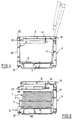
- - la figure 1 est une vue en perspective d'un dispositif selon l'invention, supportant un empilement de feuilles de verre,
- - la figure 2 est une vue en élévation de l'avant du dispositif,
- - la figure 3 est une vue analogue à la figure 2, montrant la mise en oeuvre des barres de calage contre un empilement de feuilles de verre,
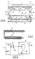
- - la figure 4 est une vue en élévation du dispositif suivant une autre face latérale de celui-ci,
- - la figure 5 est une vue analogue à la figure 4, montrant l'une des barres de calage en appui contre l'empilement des feuilles de verre,
- - la figure 6 est une vue analogue à la figure 3, montrant la fixation de l'empilement des feuilles de verre au moyen d'un lien, ou film étirable emprisonnant les barres de calage latérales,
- - la figure 7 est une vue agrandie en coupe longitudinale partielle d'une barre de calage et de son articulation à la base du dispositif,
- - la figure 8 est une vue agrandie partielle, d'une barre réglable de la face dorsale et du trou de fixation correspondant.
- FIG. 1 is a perspective view of a device according to the invention, supporting a stack of glass sheets,
- FIG. 2 is an elevation view of the front of the device,
- FIG. 3 is a view similar to FIG. 2, showing the implementation of the wedging bars against a stack of glass sheets,
- FIG. 4 is an elevation view of the device along another lateral face of the latter,
- FIG. 5 is a view similar to FIG. 4, showing one of the wedging bars pressing against the stack of glass sheets,
- FIG. 6 is a view similar to FIG. 3, showing the fixing of the stack of glass sheets by means of a link, or stretch film trapping the lateral wedging bars,
- FIG. 7 is an enlarged view in partial longitudinal section of a setting bar and of its articulation at the base of the device,
- - Figure 8 is a partial enlarged view of an adjustable bar of the dorsal face and the corresponding fixing hole.
Dans la réalisation des figures annexées, le dispositif pour supporter et transporter un empilement de feuilles de verre 1, telles que vitres latérales ou custodes d'automobile, comporte une base 2, sensiblement rectangulaire, par exemple en bois, recevant cet empilement par la tranche des feuilles de verre. Cette base 2 est surmontée à l'un de ses bords 3 par une paroi dorsale 4 servant d'appui pour l'empilement de feuilles de verre 1. Le bord 5 de la base 2 opposé à la paroi dorsale 4 comprend à chaque extrémité un montant Sa dont l'extrémité supérieure 5b est reliée par une barre 6 à l'extrémité adjacente 7a du bord supérieur 7 de la paroi dorsale 4.In the embodiment of the appended figures, the device for supporting and transporting a stack of
La base 2 est composée de barreaux 8 s'étendant perpendiculairement aux bords 3 et 5.The
Conformément à l'invention, la base 2 porte deux barres espacées 9 sensiblement parallèles à ses deux bords perpendiculaires à la paroi dorsale 4, ces barres 9 étant montées de façon articulée à la base 2 pour pouvoir pivoter entre une position dans laquelle elles reposent sur la base 2 (voir figure 2) et une position dans laquelle elles s'étendent à une hauteur variable au-dessus de la base 2 (voir figure 3).According to the invention, the
Dans la réalisation représentée, les barres 9 présentent à chaque extrémité un bras 11 sensiblement perpendiculaire à la barre 9 et dont l'extrémité opposée à celle-ci est fixée de façon articulée au bord avant 5 de la base 2 qui est parallèle à la paroi dorsale 4.In the embodiment shown, the
Les montants 5a sont fixés de façon amovible par emboîtement aux extrémités opposées 5c du bord 5 de la base 2.The
De plus, l'extrémité 5b de chaque montant 5a opposée à la base 2 est fixée de façon articulée en 12 à la barre de liaison 6 avec la paroi dorsale 4. Cette barre de liaison 6 est elle-même fixée de façon articulée en 13 à cette paroi dorsale 4. Ainsi, chaque montant Sa peut être replié vers la barre de liaison 6 (voir position en pointillés représentée sur la figure 4). De plus, l'ensemble formé par le montant replié 5a et la barre 6 peut être pivoté vers le haut, autour de l'articulation 13, au-dessus de la paroi dorsale 4, comme également montré en pointillés sur la figure 4.In addition, the
Dans cette position pivotée, les faces latérales du dispositif sont totalement dégagées, de même que sa face avant (pour l'empilage, la fixation des vitrages au dosseret 4, ou dépilage au déchargement).In this pivoted position, the lateral faces of the device are completely free, as is its front face (for stacking, fixing the glazing to the backsplash 4, or unstacking during unloading).
Des moyens sont prévus pour maintenir le montant 5a en position repliée vers la barre de liaison 6. Ces moyens peuvent être constitués par un crochet 14 reliant la barre 6 à l'extrémité du montant replié 5a. Dans cette position, la barre 6 est retenue en position horizontale par une butée 15.Means are provided for maintaining the upright 5a in the folded position towards the connecting
Par ailleurs, des moyens sont prévus pour maintenir le montant 5a en position pivotée vers le haut au-dessus de la paroi dorsale 4. Ces moyens sont formés par une butée 15 ménagée aux extrémités opposées 7a du bord supérieur 7 de la paroi dorsale, contre laquelle vient en appui l'extrémité 6a de la barre 6 adjacente à l'articulation 13.Furthermore, means are provided for holding the upright 5a in the pivoted upward position above the back wall 4. These means are formed by a
On voit également sur les figures 1, 2 et 3 que la paroi dorsale est constituée de barres espacées 16, 17 reliant la base 2 au bord supérieur 7 de cette paroi dorsale 4. Les deux barres d'extrémité 17 sont fixées de façon réglable au bord supérieur 7 de la paroi dorsale 4 et à la base 2. Ce réglage est réalisé par introduction de tétons portés par les barres 17 dans des trous 18, comme on le verra plus en détail plus loin, ce qui permet de rapprocher ou d'espacer ces barres 17 l'une de l'autre en fonction des dimensions de l'empilement de feuilles 1.It can also be seen in FIGS. 1, 2 and 3 that the back wall consists of spaced apart
Par ailleurs, la base 2 présente des faces latérales ajourées 19, 20 pour permettre l'introduction de la fourche d'un engin de manutention ou de levage.Furthermore, the
D'autre part, la face inférieure de la base 2 comporte à chaque coin un doigt 21 en saillie vers le bas. Les montants 5a comportent à leur extrémité supérieure 5b une ouverture 22 apte à recevoir chacun, un doigt en saillie 21 de la base 2 et le bord supérieur 7 de la paroi dorsale 4, comporte à chaque extrémité 7a une ouverture 23 apte à recevoir chacune l'un des deux autres doigts 21 en saillie de la base 2. Cette face inférieure de la base 2 ainsi que le haut des montants 7 et 5 peuvent être avantageusement remplacés par ceux décrits dans le brevet français 2 506 728 de la demanderesse.On the other hand, the underside of the
On peut ainsi gerber plusieurs dispositifs les uns sur les autres, comme indiqué en pointillés sur la figure 6.It is thus possible to stack several devices on top of each other, as indicated by dotted lines in FIG. 6.
La figure 7 montre en détail comment les barres de calage 9 sont montées pivotantes sur la base 2.FIG. 7 shows in detail how the
Dans cette réalisation, ces barres 9 sont constituées par une tige ou tube plié engagé dans un perçage 24 pratiqué dans une barre 8 de façon à permettre le pivotement. La partie de la barre 9 destinée à venir en contact avec l'empilement de feuilles 1 est recouverte par un manchon en caoutchouc 25 évitant tout risque de dégradation des feuilles de verre et permettant d'absorber les chocs et les vibrations lors du transport.In this embodiment, these
La figure 8 montre la fixation amovible d'une barre 17 dans un trou 18 pratiqué dans une plaque 26 fixée en haut de la paroi dorsale 4.FIG. 8 shows the removable fixing of a
Le téton 27 fixé à la barre 17 présente une tête élargie 27a qui s'engage dans l'ouverture 18 et se verrouille dans la partie basse rétrécie 18a de celle-ci.The
Le dispositif pour supporter et transporter l'empilement de feuilles de verre 1, que l'on vient de décrire, présente les principaux avantages suivants.The device for supporting and transporting the stack of
Les barres de calage 9 montées pivotantes, permettent d'assurer un calage latéral efficace des articles en verre 1 tout en étant aptes à s'adapter à des feuilles de verre de dimensions différentes, comme le montre la figure 3.The wedging bars 9 pivotally mounted, ensure efficient lateral wedging of the
Ces barres de calage 9 peuvent être maintenues en appui sur les côtés de l'empilement de feuilles de verre 1 à l'aide de liens appropriés flexibles ou non.These wedging
Le calage peut être complété par un lien 28 entourant l'empilement 1 comme indiqué sur la figure 6, ainsi que les barres verticales 16, 17 de la face dorsale 4.The setting can be completed by a
Le pivotement des montants 5a et des barres supérieures 6 vers le haut permet de dégager entièrement l'une ou les deux faces latérales du dispositif, de sorte que les feuilles de verre peuvent être chargées facilement sur la base 2 non seulement par la face avant, mais également par l'une ou l'autre de ces faces latérales.The pivoting of the
Le fait que les barres 17 de la face dorsale 4 soient réglables, permet d'ajuster la position de celles-ci en fonction des dimensions des feuilles de verre 1, ce qui facilite leur calage contre la face dorsale 4.The fact that the
Par ailleurs, du fait que toutes les faces latérales de la base 2 soient ajourées, toutes ces faces peuvent être pénétrées par les fourches d'un engin de manutention, ce qui facilite considérablement le déplacement du dispositif.Furthermore, the fact that all the lateral faces of the
Etant donné que les dispositifs sont gerbables les uns sur les autres et encastrables les uns dans les autres, ces dispositifs occupent un espace réduit, ce qui facilite leur stockage.Since the devices are stackable on top of each other and built into each other, these devices occupy a reduced space, which facilitates their storage.
Bien entendu, l'invention n'est pas limitée aux exemples de réalisation que l'on vient de décrire, et on peut apporter à ceux-ci de nombreuses modifications sans sortir du cadre de l'invention.Of course, the invention is not limited to the exemplary embodiments which have just been described, and many modifications can be made to them without departing from the scope of the invention.
Claims (9)
Applications Claiming Priority (2)
| Application Number | Priority Date | Filing Date | Title |
|---|---|---|---|
| FR8908816A FR2649082B1 (en) | 1989-06-30 | 1989-06-30 | DEVICE FOR SUPPORTING AND TRANSPORTING GLASS SHEETS |
| FR8908816 | 1989-06-30 |
Publications (2)
| Publication Number | Publication Date |
|---|---|
| EP0406121A2 true EP0406121A2 (en) | 1991-01-02 |
| EP0406121A3 EP0406121A3 (en) | 1991-03-13 |
Family
ID=9383346
Family Applications (1)
| Application Number | Title | Priority Date | Filing Date |
|---|---|---|---|
| EP19900401885 Withdrawn EP0406121A3 (en) | 1989-06-30 | 1990-06-29 | Device for supporting and transporting sheets of glass |
Country Status (4)
| Country | Link |
|---|---|
| EP (1) | EP0406121A3 (en) |
| DE (1) | DE406121T1 (en) |
| ES (1) | ES2019859A4 (en) |
| FR (1) | FR2649082B1 (en) |
Cited By (5)
| Publication number | Priority date | Publication date | Assignee | Title |
|---|---|---|---|---|
| FR2740435A1 (en) * | 1995-10-16 | 1997-04-30 | Ppg Ind Glass Sa | Stockage container for vehicle windscreens |
| FR2757831A1 (en) * | 1996-12-27 | 1998-07-03 | Jefmag | Pallet for handling tall articles, e.g. doors or window frames |
| EP1106532A1 (en) * | 1999-12-10 | 2001-06-13 | Glaverbel | Device to support and transport sheets of glass |
| CN104640790A (en) * | 2013-01-28 | 2015-05-20 | 李赛克奥地利有限公司 | Device having pivotable compartments |
| CN104843612A (en) * | 2015-05-27 | 2015-08-19 | 安徽安凯汽车股份有限公司 | Bus foreside windscreen storing and transferring tool |
Citations (3)
| Publication number | Priority date | Publication date | Assignee | Title |
|---|---|---|---|---|
| FR2387863A1 (en) * | 1977-04-21 | 1978-11-17 | Juergens Walter | Window pane transportation frame - has lateral retaining wing and hinged fixed hoop acting as width wise pane separator |
| FR2506728A1 (en) * | 1981-05-29 | 1982-12-03 | Boussois Sa | DEVICE FOR HANDLING SHEET ITEMS |
| EP0216690A2 (en) * | 1985-09-16 | 1987-04-01 | Saint-Gobain Vitrage International | Handling device for sheet-shaped articles |
-
1989
- 1989-06-30 FR FR8908816A patent/FR2649082B1/en not_active Expired - Lifetime
-
1990
- 1990-06-29 EP EP19900401885 patent/EP0406121A3/en not_active Withdrawn
- 1990-06-29 DE DE1990401885 patent/DE406121T1/en active Pending
- 1990-06-29 ES ES90401885T patent/ES2019859A4/en active Pending
Patent Citations (3)
| Publication number | Priority date | Publication date | Assignee | Title |
|---|---|---|---|---|
| FR2387863A1 (en) * | 1977-04-21 | 1978-11-17 | Juergens Walter | Window pane transportation frame - has lateral retaining wing and hinged fixed hoop acting as width wise pane separator |
| FR2506728A1 (en) * | 1981-05-29 | 1982-12-03 | Boussois Sa | DEVICE FOR HANDLING SHEET ITEMS |
| EP0216690A2 (en) * | 1985-09-16 | 1987-04-01 | Saint-Gobain Vitrage International | Handling device for sheet-shaped articles |
Cited By (7)
| Publication number | Priority date | Publication date | Assignee | Title |
|---|---|---|---|---|
| FR2740435A1 (en) * | 1995-10-16 | 1997-04-30 | Ppg Ind Glass Sa | Stockage container for vehicle windscreens |
| FR2757831A1 (en) * | 1996-12-27 | 1998-07-03 | Jefmag | Pallet for handling tall articles, e.g. doors or window frames |
| EP1106532A1 (en) * | 1999-12-10 | 2001-06-13 | Glaverbel | Device to support and transport sheets of glass |
| BE1013176A3 (en) * | 1999-12-10 | 2001-10-02 | Glaverbel | Container for transportation of materials rigid sheets. |
| CN104640790A (en) * | 2013-01-28 | 2015-05-20 | 李赛克奥地利有限公司 | Device having pivotable compartments |
| CN104640790B (en) * | 2013-01-28 | 2017-06-23 | 李赛克奥地利有限公司 | Device with pivotable lattice section |
| CN104843612A (en) * | 2015-05-27 | 2015-08-19 | 安徽安凯汽车股份有限公司 | Bus foreside windscreen storing and transferring tool |
Also Published As
| Publication number | Publication date |
|---|---|
| ES2019859A4 (en) | 1991-07-16 |
| EP0406121A3 (en) | 1991-03-13 |
| FR2649082B1 (en) | 1991-11-22 |
| FR2649082A1 (en) | 1991-01-04 |
| DE406121T1 (en) | 1991-05-02 |
Similar Documents
| Publication | Publication Date | Title |
|---|---|---|
| EP0778169B1 (en) | Tarpaulin arrangement for lorries | |
| BE1007277A4 (en) | Glove with lid and folding tablet. | |
| EP0208624A1 (en) | Multiple purpose carrying container device | |
| EP1666365A1 (en) | Palletcontainer with two support surfaces | |
| EP0442780B1 (en) | Pallet for transport of glass panels | |
| EP0406121A2 (en) | Device for supporting and transporting sheets of glass | |
| CH657975A5 (en) | STORAGE AND EXPOSURE DEVICE. | |
| EP1257458B1 (en) | Trolley basket for self-service shop | |
| FR2533202A1 (en) | Variable geometry positioning apparatus, for loads whose periphery is or is not fragile and especially for casks or handling vats. | |
| FR2531018A1 (en) | Movable cover for lorry loads | |
| FR2755675A1 (en) | Storage and transport of bumpers | |
| FR2711625A1 (en) | Transport device for stems of bananas | |
| EP0216690A2 (en) | Handling device for sheet-shaped articles | |
| EP0554185B1 (en) | Storage unit comprising a carrying case and a support | |
| EP0279999B1 (en) | Crate support for trolleys and trolley with such a support | |
| FR2578959A1 (en) | Improvements to open-hearth fireplaces equipped with a retractable glass wall | |
| FR2707962A1 (en) | Blocking device for a movable container for collecting household waste | |
| FR2577202A1 (en) | Rack for packaging a batch of objects, particularly heavy and voluminous objects such as bottles of liquefied gas | |
| FR2653093A1 (en) | Device for supporting and holding bags in the open position particularly postal bags | |
| FR2775871A1 (en) | Folding fish trap with mesh walls | |
| FR2757831A1 (en) | Pallet for handling tall articles, e.g. doors or window frames | |
| BE1007147A4 (en) | Process and device for handling, loading and transporting long objects on avehicle roof | |
| FR2634101A1 (en) | Device for force-feeding poultry | |
| FR2728857A1 (en) | BUILT-IN HANDLING TROLLEY | |
| FR2813871A1 (en) | Folding frame for supporting pocketed sack for transporting car doors has grid at top which supports sack and is mounted on uprights which are pivoted on base, tops of uprights being connected to grid by lockable bars |
Legal Events
| Date | Code | Title | Description |
|---|---|---|---|
| PUAI | Public reference made under article 153(3) epc to a published international application that has entered the european phase |
Free format text: ORIGINAL CODE: 0009012 |
|
| 17P | Request for examination filed |
Effective date: 19900705 |
|
| AK | Designated contracting states |
Kind code of ref document: A2 Designated state(s): BE DE ES GB IT LU |
|
| PUAL | Search report despatched |
Free format text: ORIGINAL CODE: 0009013 |
|
| ITCL | It: translation for ep claims filed |
Representative=s name: BARZANO' E ZANARDO ROMA S.P.A. |
|
| GBC | Gb: translation of claims filed (gb section 78(7)/1977) | ||
| AK | Designated contracting states |
Kind code of ref document: A3 Designated state(s): BE DE ES GB IT LU |
|
| DET | De: translation of patent claims | ||
| 17Q | First examination report despatched |
Effective date: 19921001 |
|
| STAA | Information on the status of an ep patent application or granted ep patent |
Free format text: STATUS: THE APPLICATION IS DEEMED TO BE WITHDRAWN |
|
| 18D | Application deemed to be withdrawn |
Effective date: 19931012 |