EP0406113A2 - Commande du dosage dans un distributeur d'adhésif - Google Patents
Commande du dosage dans un distributeur d'adhésif Download PDFInfo
- Publication number
- EP0406113A2 EP0406113A2 EP90401861A EP90401861A EP0406113A2 EP 0406113 A2 EP0406113 A2 EP 0406113A2 EP 90401861 A EP90401861 A EP 90401861A EP 90401861 A EP90401861 A EP 90401861A EP 0406113 A2 EP0406113 A2 EP 0406113A2
- Authority
- EP
- European Patent Office
- Prior art keywords
- control rod
- pneumatic
- cartridge
- piston
- adhesive
- Prior art date
- Legal status (The legal status is an assumption and is not a legal conclusion. Google has not performed a legal analysis and makes no representation as to the accuracy of the status listed.)
- Granted
Links
Images


Classifications
-
- B—PERFORMING OPERATIONS; TRANSPORTING
- B05—SPRAYING OR ATOMISING IN GENERAL; APPLYING FLUENT MATERIALS TO SURFACES, IN GENERAL
- B05C—APPARATUS FOR APPLYING FLUENT MATERIALS TO SURFACES, IN GENERAL
- B05C17/00—Hand tools or apparatus using hand held tools, for applying liquids or other fluent materials to, for spreading applied liquids or other fluent materials on, or for partially removing applied liquids or other fluent materials from, surfaces
- B05C17/005—Hand tools or apparatus using hand held tools, for applying liquids or other fluent materials to, for spreading applied liquids or other fluent materials on, or for partially removing applied liquids or other fluent materials from, surfaces for discharging material from a reservoir or container located in or on the hand tool through an outlet orifice by pressure without using surface contacting members like pads or brushes
- B05C17/015—Hand tools or apparatus using hand held tools, for applying liquids or other fluent materials to, for spreading applied liquids or other fluent materials on, or for partially removing applied liquids or other fluent materials from, surfaces for discharging material from a reservoir or container located in or on the hand tool through an outlet orifice by pressure without using surface contacting members like pads or brushes with pneumatically or hydraulically actuated piston or the like
-
- B—PERFORMING OPERATIONS; TRANSPORTING
- B05—SPRAYING OR ATOMISING IN GENERAL; APPLYING FLUENT MATERIALS TO SURFACES, IN GENERAL
- B05C—APPARATUS FOR APPLYING FLUENT MATERIALS TO SURFACES, IN GENERAL
- B05C17/00—Hand tools or apparatus using hand held tools, for applying liquids or other fluent materials to, for spreading applied liquids or other fluent materials on, or for partially removing applied liquids or other fluent materials from, surfaces
- B05C17/005—Hand tools or apparatus using hand held tools, for applying liquids or other fluent materials to, for spreading applied liquids or other fluent materials on, or for partially removing applied liquids or other fluent materials from, surfaces for discharging material from a reservoir or container located in or on the hand tool through an outlet orifice by pressure without using surface contacting members like pads or brushes
- B05C17/00553—Hand tools or apparatus using hand held tools, for applying liquids or other fluent materials to, for spreading applied liquids or other fluent materials on, or for partially removing applied liquids or other fluent materials from, surfaces for discharging material from a reservoir or container located in or on the hand tool through an outlet orifice by pressure without using surface contacting members like pads or brushes with means allowing the stock of material to consist of at least two different components
Definitions
- This invention pertains to an improved, pneumatically-actuated dispenser for an adhesive, such as a two-part epoxy adhesive.
- This invention provides dosage control for the adhesive dispenser.
- Two-part adhesives such as two-part epoxy adhesives
- Two-part adhesives are used widely, in large doses at construction sites and elsewhere, particularly but not exclusively to set studs, anchors, and other hardware into holes bored or formed otherwise in concrete or masonry.
- Such adhesives are available commercially in two-chamber cartridges, which fit into various manually-actuated or pneumatically-actuated dispensers.
- a commercial source for such adhesives in such cartridges, for such manually-actuated dispensers, and for such pneumatically-actuated dispensers is ITW Ramset/Red Head (a division of Illinois Tool Works Inc.) of Wood Dale, Illinois.
- a single dose may not use all contents of such a cartridge, which may contain enough of such adhesive, or of each part of such adhesive, to provide two, three, or more doses. It is known to provide a visible scale, on an exposed surface of such a cartridge, as a way to measure each such dose.
- a manually actuated or pneumatically actuated dispenser it has been necessary heretofore for the user to judge visually, as by movement of a rod of the dispenser vis-a-vis such a scale if provided, when each dose has been dispensed.
- This invention provides an improved, pneumatically actuatable dispenser for an adhesive, as provided in a cartridge of a known type.
- a cartridge has a chamber containing the adhesive, a nozzle mounted to a first end of the cartridge, and a plunger accessible from a second end of the cartridge and displaceable through the chamber, toward the nozzle, so as to force the adhesive into the nozzle, through which the adhesive is injected, as into a hole bored or formed otherwise in concrete or masonry.
- each chamber contains one of two parts of the adhesive
- the cartridge has a mixing nozzle, which is mounted to a first end of the cartridge, and which is arranged to receive one of the parts of the adhesive from each chamber and to mix such parts.
- each chamber has a plunger, which is accessible from a second end of the cartridge, and which is displaceable through such chamber, toward the nozzle, in which the parts of the adhesive are mixed, and through which the mixed parts of the adhesive are injected.
- the improved dispenser comprises a frame, which is adapted to hold such a cartridge, and a pneumatic mechanism, which is connectable to a source of pressurized air, such as an air cylinder or an air compressor, and which is attached to the frame so as to support the frame with such a cartridge held by the frame.
- a source of pressurized air such as an air cylinder or an air compressor
- the pneumatic mechanism comprises a pneumatic cylinder, which is attached to the frame, and a pneumatic piston, which is arranged to be pneumatically driven within the pneumatic cylinder, selectively in a forward direction or in a reverse direction.
- the pneumatic piston may be thus described as double-acting.
- the pneumatic mechanism comprises a piston rod for each cartridge chamber. If one piston rod is used for such a cartridge having a single chamber, the piston rod is arranged to drive the plunger of the cartridge toward the nozzle of the cartridge when the pneumatic piston is driven in a forward direction and to withdraw from the plunger when the pneumatic piston is driven in a reverse direction. If a pair of piston rods are used for such a cartridge having two chambers, each piston rod is arranged to drive the plunger of a respective one of the chambers toward the nozzle of tho cartridge when the pneumatic piston is driven in a forward direction and to withdraw from the same plunger when the pneumatic piston is driven in a reverse direction.
- the pneumatic mechanism comprises several pneumatic valves, namely a manually actuatable first valve, a manually actuatable second valve, and a mechanically actuatable third valve.
- the first valve is arranged, when actuated manually with the pneumatic mechanism connected to the source of pressurized air, to deliver pressurized air from the source to the pneumatic cylinder so as to drive the pneumatic piston in the forward direction.
- the second valve is arranged, when actuated manually with the pneumatic mechanism connected to the source of pressurized air, to deliver pressurized air from the source to the pneumatic cylinder so as to drive the pneumatic piston in the reverse direction.
- the first and second valves are similar to valves used similarly on adhesive dispensers as known heretofore.
- the third valve which is novel in an adhesive dispenser, is arranged, when actuated mechanically (in a manner to be later described) while the first valve is connected to a source of pressurized air and actuated, to block pressurized air from flowing from the first valve into the pneumatic cylinder and simultaneously to vent pressurized air, as delivered previously by the first valve, from the pneumatic cylinder to ambient atmosphere.
- Novel means are provided for limiting conjoint movement of the pneumatic piston and the piston rod, or piston rods, in the forward direction so as to enable such dispenser to dispense an adjustably controlled dose of an adhesive, or of the mixed parts of an adhesive, from such a cartridge held by the frame.
- Such means are adjustable by the user.
- the means mentioned in the preceding paragraph are provided by a first control rod, a second control rod, means operable manually and selectively by a user for certain purposes described below, and an actuator for the third valve.
- the first control rod which is similar to rods used on adhesive dispensers as known heretofore, is arranged to be conjointly driven with the pneumatic piston, along an exterior surface of such a cartridge held by the frame, without interfering with the cartridge.
- the second control rod is arranged to be selectively linked to or unlinked from the first control rod so as to move conjointly with the first control rod, in parallel relation to the first control rod, when linked to the first rod, and so as to be independently movable when unlinked from the first control rod whereby the second control rod can return to a home position.
- the last-mentioned means are operable manually and selectively by a user to link the second control rod to the first control rod, at any position within a range of possible positions along the first control rod, or to unlink the second control rod from the first control rod.
- the means described in the preceding sentence comprise a linking lever, which is attached to one end of the second control rod so as to retain the linking lever on the end of the second control rod but to permit a limited range of pivotal movement of the linking lever on the end of the second control rod.
- the linking lever has an aperture, through which the first control rod extends with a loose fit allowing the first control rod to pass freely through the aperture except when pivotal movement of the linking lever causes the linking lever frictionally to engage the first control rod.
- Coacting means are provided, namely means for biasing the second control rod in the reverse direction and means operable manually by a user to position the linking lever selectively in a pivotal position permitting the first control rod to pass freely through the aperture or in a pivotal position causing the linking lever frictionally to engage the first control rod as mentioned.
- the means operable manually by a user to position the linking lever comprises a cam, which is mounted operatively, more preferably on the pneumatic cylinder or less preferably to the linking lever, and which is arranged to be manually adjusted between a condition wherein the cam engages and is interposed between the linking lever and adjacent structure so as to position the linking lever in the pivotal position permitting the first control rod to pass freely through the aperture and a condition wherein the cam permits the means for biasing the second control rod in the rearward direction to pivot the linking lever, via the second control rod, to a pivotal position causing the linking lever frictionally to engage the first control rod as mentioned.
- the actuator mentioned above is positionable adjustably along the second control rod, at any position within a range of possible positions along the second control, for conjoint movement with the second control rod. Also, the actuator is arranged to actuate the third valve (so as to block pressurized air from flowing from the first valve into the pneumatic cylinder and simultaneously to vent pressurized air, as delivered previously by the first valve, from the pneumatic cylinder) upon conjoint movement of the first control rod, the second control rod, and the actuator from respective dose-initiating positions relative to the pneumatic cylinder to respective dose-concluding positions relative thereto.
- the third valve so as to block pressurized air from flowing from the first valve into the pneumatic cylinder and simultaneously to vent pressurized air, as delivered previously by the first valve, from the pneumatic cylinder
- the piston rod, or piston rods can begin to drive the plunger, or plungers, of such a cartridge held by the frame toward the nozzle of the cartridge.
- the plunger, or plungers, of such a cartridge has, or have, been displaced by a distance correlating to a controlled dose of adhesive, or of the mixed parts of an adhesive, from the cartridge.
- the actuator mentioned above can be adjustably positioned along the second control rod so as to enable the dispenser, when the second control rod is linked to the first control rod, to dispense a control dosage of an adhesive, or of the mixed parts of an adhesive, from such a cartridge held by the frame with such dose being less than full contents of such cartridge, e.g., with such dose being one-third of such contents.
- the pneumatic mechanism may comprise a manually actuatable fourth valve, which is arranged, when actuated with the pneumatic mechanism connected to the source of pressurized air, to divert pressurized air entering the pneumatic mechanism, along with a hose connected to the fourth valve and, preferably, a nozzle connected to the hose.
- the fourth valve and the hose can be advantageously used to blow water, debris, or both from a hole bored or formed otherwise in concrete or masonry, just before an adhesive is dispensed into the hole.
- a similar arrangement of such a valve and a hose, either with or without a nozzle connected to the hose, can be advantageously used, in like manner, in any pneumatically actuatable dispenser for an adhesive, as provided in such a cartridge, if the dispenser comprises a frame, which is adapted to hold the cartridge, and a pneumatic mechanism, which is connectable to a source of pressurized air, which is attached to the frame, and which is operable to dispense an adhesive from such a cartridge held by the frame.
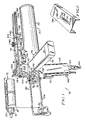
- a pneumatically actuated dispenser 10 for a two-part adhesive such as a two-part epoxy adhesive
- a cartridge 12 constituting a preferred embodiment of this invention.
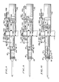
- the cartridge 12 which appears in FIGURE 1 and also in FIGURES 8, 9, and 10, is an example of cartridges with which the dispenser 10 is useful.
- the cartridge 12 has two chambers 14, which are tubular with circular cross-sections, and a replaceable mixing nozzle 16, which is attached at a first or front end of the cartridge 12 by a threaded connector 18, and which has an elongate tip, as shown in FIGURES 8, 9, and 10.
- Each chamber 14 contains one part of the adhesive, typically but not necessarily in gel, paste, semi-liquid, or high viscosity liquid form, and has a plunger 20 (one shown; see FIGURES 8 through 10) which seals each adhesive part within its cartridge chamber, and which is accessible from a second or back end of the cartridge 12, and which is displaceable through such chamber 14, toward the nozzle 16.
- the nozzle 16 is arranged to receive one part of the adhesive from each chamber 14, to mix the parts of the adhesive, and to inject the mixed parts of the adhesive, as into a hole (not shown) bored or formed otherwise in concrete or masonry, just after water and debris have been blown from the hole in a manner to be later described.
- the adhesive may be thus used to set a stud, anchor, or other hardware (not shown) in the hole.
- the cartridge 12 is formed with a longitudinal valley 22, which extends along its upper, exterior surface.
- Such cartridges containing two-part epoxy adhesives are available commercially from ITW Ramset/Red Head (a division of Illinois Tool Works Inc.) of Wood Dale, Illinois.
- the front frame 30 comprises a cradle 32, which is fabricated from sheet steel, and which fits under and partially around the nozzle 16, so as to limit axial movement of the connector 18 when the connector 18 is threaded onto the cartridge 12, and a wire bracket 34, which is fabricated from steel wire, and which has a bight 36 adapted to fit under a front portion of a cartridge exemplified by the cartridge 12.
- the wire bracket 34 which is welded to the cradle 32 at spaced locations near the bight 36, is secured at its opposite ends 38 to the pneumatic mechanism, via a mounting plate 40, which is mounted integrally to a front surface of a lower mounting block 42.
- the pneumatic mechanism 50 comprises a pneumatic cylinder 52, a handle 54 extending downwardly from the lower mounting block 42, and a handle 56 extending laterally from the lower mounting block 42, and is connectable to a source 58 of pressurized air, under regulated pressure, such as an air compressor, which is preferred, or an air cylinder.
- the source 58 is represented diagrammatically in FIGURE 12.
- the pneumatic mechanism 50 is connectable to the source 58 of pressurized air, via a conventional fitting 60, which is provided at a lower end of the downwardly extending handle 54, and a flexible pneumatic line 62, which is shown fragmentarily in FIGURE 1, and diagrammatically in FIGURES 11 and 12, and a pressure regulator 64, which is shown diagrammatically in FIGURE 12.
- a double-acting pneumatic piston 70 (see FIGURES 8 through 12) is arranged, in a conventional manner, to be pneumatically driven within the pneumatic cylinder 52, selectively in a forward direction or in a reverse direction.
- Two piston rods 72 are provided, which operate in tandem, one for each chamber of a cartridge like the cartridge 12.
- Each piston rod 72 extends through a suitably sealed aperture in a front end of the pneumatic cylinder 52, and through suitable apertures in the lower mounting block 42 and in the mounting plate 40, and is provided at its distal end with an enlarged boss 74, on which is mounted a plunger-engaging element 76 made of synthetic rubber or equivalent material.
- Each piston rod 72 is arranged, via the plunger-engaging element 76 mounted on the enlarged boss 74 on the distal end of such piston rod 72, to drive the plunger 20 of a respective one of the chambers of a cartridge exemplified by the cartridge 12, as held by the front frame 30, when the pneumatic piston 70 is driven in a forward direction and to withdraw from the same plunger when the pneumatic piston 70 is driven oppositely, i.e., in a reverse direction.
- the enlarged bosses 74 and the plunger-engaging elements 76 conform approximately, in outer diameter, to the plungers of such a cartridge, e.g., the plungers 20.
- the pneumatic mechanism 50 comprises several pneumatic valves, namely a manually actuatable first valve 80, a manually actuatable second valve 82, a mechanically actuatable third valve 84, and a manually actuatable fourth valve 86, each as represented diagrammatically in FIGURES 11 and 12.
- the first valve 80 is mounted in the downwardly extending handle 54, so as to be manually actuatable via an external button 92 carried on a stem 94 (see FIGURE 12) of the first valve 80.
- the second valve 82 is mounted in the laterally extending handle 56 so as to be manually actuatable via an external button 96 carried on a stem 98 (see FIGURE 12) of the second valve 82.
- the third valve 84 is mounted on the pneumatic cylinder 52 so as to be mechanically actuatable in a manner to be later described.
- the fourth valve 86 is mounted in the downwardly extending handle 54, beneath the first valve 80, so as to be manually actuatable via an external button 102 carried on a stem 104 (see FIGURE 12) of the fourth valve 86.
- the first valve 83 is arranged, when actuated with the pneumatic mechanism 50 connected to the source 58 of pressurized air, to deliver pressurized air from the source 58 to the pneumatic cylinder 52 so as to drive the pneumatic piston 70 in the forward direction.
- the second valve 82 is arranged, when actuated with the pneumatic mechanism 50 connected to the source 58 of pressurized air, to deliver pressurized air from the source 58 to the pneumatic cylinder 52 so as to drive the pneumatic piston 70 in the reverse direction.
- Pneumatic lines connected to and from the first valve 80 and pneumatic lines connected to and from the second valve 82 are represented diagrammatically in FIGURES 11 and 12. If the first valve 80 and the second valve 82 should be simultaneously actuated with the pneumatic mechanism 50 connected to the source of pressurized air, the pneumatic piston 70 would stall and would not be pneumatically driven in either direction.
- the third valve 84 is arranged, when actuated while the first valve 80 is actuated, to block pressurized air from flowing from the first valve 80 into the pneumatic cylinder 52 and simultaneously to vent pressurized air, as delivered previously by the first valve 80, from the pneumatic cylinder 52, through the third valve 84 and through a port 106 (see FIGURE 1) to ambient atmosphere, whereby the pneumatic piston 70 tends to be immediately arrested. If each part of an adhesive provided in a cartridge exemplified by the cartridge 12 is provided in gel, paste, semi-liquid, or high viscosity liquid form, as mentioned above, inertial movement of the pneumatic piston 70 tends to be very insignificant.
- the first control rod 112 extends through a suitably sealed aperture in the front end of the pneumatic cylinder 52, and through suitable apertures in the lower mounting block 42 and in the mounting plate 40, and is arranged to be conjointly driven with the pneumatic piston 70, along an upper, exterior surface of a cartridge exemplified by the cartridge 12, as held by the front frame 30, and along a longitudinal valley exemplified by the valley 22 of the cartridge 12. If the cartridge bears a visible scale (not shown) on its upper, exterior surface, a user can judge visually, by movement of the first control rod 112 vis-a-vis the scale, movement of the pneumatic piston 70, conjointly with the first control rod 112, as in adhesive dispensers as known heretofore.
- the second control rod 114 is arranged to be selectively linked to or unlinked from the first control rod 112 so as to remove conjointly with the first control rod 112, in parallel relation to the first control rod 112, when linked to the first control rod 112, and so as to be independently movable when unlinked from the first control rod 112.
- the second control rod 114 is mounted for axial movement, in the forward direction and in the reverse direction, by an upper mounting block 120, which is mounted integrally on the lower mounting block 42, and which has a suitable aperture for the second control rod 114, and by a mounting strap 122, which extends rearwardly from the upper mounting block 120, and which has a bent end 124 having a suitable aperture for the second control rod 114.
- a rearmost end 126 of the second control rod 114 is threaded.
- a cap nut 128 is threaded onto the threaded end 126.
- a coiled spring 130 which is deployed around the second control rod 114, between the bent end 124 of the mounting strap 122 and the cap nut 128, biases the second control rod 114 in the rearward direction.
- the means 116 mentioned above as operable manually and selectively by a user prevent the second control rod 114, as biased by the coiled spring 130, from being pulled through the upper mounting block 120.
- Such means 116 comprise a linking lever 140 having an aperture 142, through which the first control rod 112 passes with sufficient clearance to permit the linking lever 140 to pivot from a position at a right angle to the first control rod 112 through an angle as large as about 10° relative to the first control rod 112, and an aperture 144, through which the second control rod 114 passes with sufficient clearance to permit the linking lever 140 to pivot through a similar angle relative to the second control rod 114, i.e., through an angle as large as about 10° relative to the second control rod 114.
- the adjacent end 146 of the second control rod 114 is fitted with a retaining clip 148, which prevents the second control rod 114, as biased by the coil spring 130, from being pulled through the aperture 144 in the linking lever 140.
- the upper mounting block 120 is offset on the lower mounting block 42, as shown in FIGURES 1, 5, and 6.
- Such means 116 also comprise a cam 150, which is mounted to the upper mounting block 120, via a vertical pin 152, for free rotation in either rotational sense about a vertical axis defined by the vertical pin 152, and which is cylindrical, except for a flat surface 154 truncating its cylindrical periphery, and except for knurling on its cylindrical periphery.
- the cam 150 engages and is interposed between upper portions of the linking lever 140 and adjacent structure provided by the upper mounting block 120, so as to position upper portions of the linking lever 140 away from the upper mounting block 120 when lower portions of the linking lever 140 bear against the lower mounting block 42, unless the cam 150 is rotated so that the flat surface 154 faces and engages the linking lever 140. If the cam 150 is rotated so that the flat surface 154 faces and engages the linking lever 140, the linking lever 140 is permitted to pivot, as biased by the coiled spring 130 biasing the second control rod 114, from a position at a right angle to the first control rod 112 through the aforesaid angles (as large as about 10°) relative to the first control rod 112 and the second control rod 114 respectively.
- the linking lever 140 when the linking lever 140 is disposed at right angles relative to the first control rod 112 and the second control rod 114 respectively, the first control rod 112 and the second control rod 114 are unlinked from each other, as occurs when the linking lever 140 is in a home position wherein the cam 152 (but not the flat surface 154) engages the linking lever 140 or when the linking lever 140 (in or away from the home position) is actuted manually.
- the actuator 118 comprises a block 158 having a suitable aperture, through which the second control rod 114 passes, and a thumb screw 160, which has a threaded shank 162.
- the thumb screw 160 can be manually loosened, so as to permit the actuator 118 to be adjustably positioned along the second control rod 114, and can be manually tightened, so as to secure the actuator 118 in a selected position along the second control rod 114.
- the actuator 118 can be adjustably positioned within a range of possible positions along the second control rod 114. The range is defined by a retaining clip 164, which is mounted in an annular groove on the second control rod 114, and by the third valve 84. See FIGURE 1.
- the actuator 118 is arranged to actuate the third valve 84 in a manner described below (so as to block pressurized air from flowing from the first valve 80 into the pneumatic cylinder 52 and simultaneously to vent pressurized air, as delivered previously by the first valve 80, from the pneumatic cylinder 52) upon conjoint movement of the first control rod 112, the second control rod 114, and the actuator 118 from respective dose-initiating positions relative to the pneumatic cylinder 52 (see e.g., FIGURE 9) where the piston rod 72 can begin (via the enlarged bosses 74 and the plunger-engaging elements 76) to drive the plungers of a cartridge exemplified by the cartridge 12, as held by the front frame 30, toward the nozzle of the cartridge to respective dose-concluding positions relative to the pneumatic cylinder 52 (see, e.g., FIGURE 10) where the plungers of the cartridge have been displaced by a distance correlating to a controlled dose of the mixed parts of an adhesive from the cartridge.
- the linking lever 140 must be manually pivoted so as to assume right angles relative to the first control rod 112 and the second control rod 114 respectively (see, e.g., FIGURE 9 wherein the linking lever 140 is shown, in phantom lines, at right angles relative thereto) whereupon the coiled spring 130 can pull the linking lever 140, via the second control rod 114, in the rearward direction until lower portions of the linking lever 140 engage the lower mounting block 42, at the home position noted above.
- the cam 150 must remain rotated (or be again rotated) so that the flat surface 154 faces and engages the linking lever 140, whereby the linking lever 140 again links the first control rod 112 and the second control rod 114 to each other.
- a cover 170 which has an elongate slot 172 for the threaded shank 162 of the thumb screw 160, and which has an aperture for the vertical pin 152 mounting the cam 150, is bolted onto the upper mounting block 120.
- the cover 170 covers the third valve 84, as a precaution against accidental or deliberate actuation of the third valve 84 by a user during injection of a dose, and covers the second control rod 114, the upper mounting block 120, the mounting strap 122, and the coiled spring 130, as a precaution against the user pinching his or her fingers.
- the cover 170 is provided with visible indicia 180, to which a user can refer when positioning the actuator 118, via the thumb screw 160, along the second control rod 114.
- means 180 are provided for ensuring rapid actuation of the third valve 84 by the actuator 118.
- the third valve 84 has an external stem 182, which is used to actuate the third valve 84, and which is biased outwardly.
- the block 158 of the actuator 118 does not directly engage the external stem 182.
- Such means 180 comprise a stepped, tubular structure 184, which is mounted to the third valve 84, over the stem 182, via a bracket 186 and a nut 188, which is threaded onto a threaded portion 190 of the structure 184, as shown.
- a spool 192 which is movable axially within the tubular structure 184, is biased toward the stem 182 by a coiled spring 194.
- a pair of detent balls 196 which are biased, in radially inward directions, by a pair of coiled springs 198, which are held by set screws 200, coact with an annular groove 202 in the spool 192 so as to retain the spool 192 in a position where the spool 192 bears against the stem 182, but where the spool 192 does not displace the outwardly biased stem 182 by any significant amount.
- the spring 194 is deployed within the tubular structure 184, between the spool 192 and a button 204, which has an external stem 206, and which is retained within the tubular structure 184 (except for the external stem 206) by a cap 208 having a suitable aperture for the external stem 206. The spring 194 biases the stem 206 outwardly.
- the block 158 of the actuator 118 is arranged to engage the outwardly biased stem 206 of the button 204, upon conjoint movement of the actuator 118 with the second control rod 114 over a distance approaching a distance correlating to a control dose, whereupon the button 204 is displaced so as to compress the coiled spring 194.
- the button 204 engages the spool 192
- the button 204 upon further movement dislodges the spool 192, so as to cam the balls 196 from the annular groove 202, onto the cylindrical surface of the spool 192, whereupon the spool 192 displaces the outwardly biased stem 182, so as to actuate the third valve 84 with a snap-action.
- the snap-action assures that the third valve 84 performs its desired functions and averts a situation wherein the first and second valves tend to be simultaneously open to air flow.
- the actuator 118 is moved back, i,e., in the reverse direction, the spool 192, the detent balls 196, the coiled spring 194, and the button 204 are returned by the outwardly biased stem 182, which bears against the spool 192, to the positions wherein they appear in FIGURE 4.
- FIGURE 5 Internal details of the fourth valve 86 are shown in FIGURE 5.
- a ball 210 which serves as a valve closure, is biased against a valve seat 212 by a coiled spring 214.
- a rounded button 216 which is carried integrally at an inner end of the stem 104, prevents the stem 104 from being pulled out of the valve 86.
- the button 102 on the stem 104 is depressed manually, the button 216 cams the ball 210 from the seat 212, whereby pressurized air entering the pneumatic mechanism 50 from the source 58 is diverted so as to exit through the seat 212.
- a hose 218 is connected to the valve 86, via a conventional coupling 220, so as to receive pressurized air exiting through the seat 212.
- the spring 214 returns the ball 210 onto the seat 212, and the ball 210 cams the button 216 so as to express the stem 104 and the button 102 as far as the button 216 permits.
- a nozzle 222 is connected to the hose 218.
- pressurized air passing through the hose 218, to the nozzle 222 can be readily directed by a user so as to blow water, debris, or both from a hole (not shown) bored of formed otherwise in concrete or masonry, just before the mixed parts of an adhesive are injected into the hole by the adhesive dispenser 10. This is done to maximize the bonding capability of the adhesive in an anchoring application.
- a cam 230 mounted rotatably on an upper portion of the linking lever 140, as by a threaded pin 232 receiving a nut 234, may be alternatively substituted for the cam 150 mounted on the upper mounting block 120 by the vertical pin 152.
- the cam 230 is selected so as to have a thickness equal approximately to the distance by which the upper mounting block 120 is offset on the lower mounting block 42.
- the cam 230 is cylindrical, except for a flat surface 236, on its cylindrical periphery, and except for knurling on its cylindrical periphery.
- the flat surface 236 enables the cam 230 to clear the cover 170 (see FIGURE 14) when it is desired to allow the linking lever 140 to pivot from a position at a right angle to the first control rod 112 through the aforesaid (non-right) angles (as large as about 10°) relative to the first control rod 112 and the second control rod 114 respectively.
- the cam 230 engages and is interposed between the linking lever 140 and adjacent structure provided by the upper mounting block 120 (see FIGURE 15) when it is desired to position the linking lever 140 at right angles relative to the first control rod 112 and the second control rod 114 respectively.
- directional terms e.g., “downwardly”, and “laterally”, upper”, “lower”, and terms of like import, refer to the dispenser 10 in a convenient orientation, in which the dispenser 10 appears in FIGURE 1 and other views of the drawings, but are not intended to limit the dispenser provided by this invention to any particular orientation.
Landscapes
- Engineering & Computer Science (AREA)
- Mechanical Engineering (AREA)
- Coating Apparatus (AREA)
- Application Of Or Painting With Fluid Materials (AREA)
- Nozzles (AREA)
Applications Claiming Priority (2)
| Application Number | Priority Date | Filing Date | Title |
|---|---|---|---|
| US373424 | 1989-06-30 | ||
| US07/373,424 US5020693A (en) | 1989-06-30 | 1989-06-30 | Dosage control for adhesive dispenser |
Publications (3)
| Publication Number | Publication Date |
|---|---|
| EP0406113A2 true EP0406113A2 (fr) | 1991-01-02 |
| EP0406113A3 EP0406113A3 (en) | 1991-06-26 |
| EP0406113B1 EP0406113B1 (fr) | 1994-11-02 |
Family
ID=23472353
Family Applications (1)
| Application Number | Title | Priority Date | Filing Date |
|---|---|---|---|
| EP90401861A Expired - Lifetime EP0406113B1 (fr) | 1989-06-30 | 1990-06-28 | Commande du dosage dans un distributeur d'adhésif |
Country Status (7)
| Country | Link |
|---|---|
| US (1) | US5020693A (fr) |
| EP (1) | EP0406113B1 (fr) |
| JP (1) | JP2822269B2 (fr) |
| KR (1) | KR0129771B1 (fr) |
| AU (1) | AU629953B2 (fr) |
| CA (1) | CA2017770C (fr) |
| DE (1) | DE69013772T2 (fr) |
Cited By (7)
| Publication number | Priority date | Publication date | Assignee | Title |
|---|---|---|---|---|
| GB2336878A (en) * | 1998-01-23 | 1999-11-03 | Ian Alexander Durrant | Dispensing gun with a reversible ratchet mechanism and a piston with a hollow rigid member and a flexible member |
| US6286718B1 (en) | 1998-01-23 | 2001-09-11 | Ian Alexander Durrant | Dispensing gun |
| EP2468419A1 (fr) * | 2010-12-23 | 2012-06-27 | P C Cox Limited | Distributeur pneumatique bidirectionnel |
| US8499977B2 (en) | 2009-10-22 | 2013-08-06 | P. C. Cox Limited | Plunger |
| US8528793B2 (en) | 2010-12-23 | 2013-09-10 | P. C. Cox Limited | Actuator |
| US8607824B2 (en) | 2010-12-23 | 2013-12-17 | P.C. Cox Limited | Valve and dispenser using the valve |
| US8870093B2 (en) | 2010-12-23 | 2014-10-28 | P.C. Cox Limited | Dispenser |
Families Citing this family (30)
| Publication number | Priority date | Publication date | Assignee | Title |
|---|---|---|---|---|
| DE9017322U1 (fr) * | 1990-12-21 | 1992-04-16 | Thera Patent Gmbh & Co Kg Gesellschaft Fuer Industrielle Schutzrechte, 8031 Seefeld, De | |
| US5203839A (en) * | 1991-06-14 | 1993-04-20 | Skaggs Kenneth R | Apparatus for dispensing adhesive materials |
| US5224629A (en) * | 1992-03-19 | 1993-07-06 | Hsich Rong Fuh | Control structure for a pneumatic sealant gun |
| EP0607102B1 (fr) * | 1993-01-15 | 1999-03-17 | Wilhelm A. Keller | Appareil distributeur pour au moins deux composants |
| US5390825A (en) * | 1993-03-10 | 1995-02-21 | Rockel; Christopher M. | Portable, self contained, two-part adhesive dispensing device |
| US5411180A (en) * | 1993-05-07 | 1995-05-02 | Innovative Technology Sales, Inc. | Self-contained hydraulic dispensing mechanism with pressure relief regulator |
| US5381931A (en) * | 1994-03-04 | 1995-01-17 | Chang; Peter J. Y. | Caulk dispensing device with multi-position thrust selection dial |
| US5720418A (en) * | 1995-08-14 | 1998-02-24 | Illinois Tool Works Inc. | Adjustable tool for dispensing viscous material, such as two-part adhesive |
| US5651397A (en) * | 1995-11-15 | 1997-07-29 | Minnesota Mining And Manufacturing Company | Dual chamber dispensing cartridge refilling device |
| US5816445A (en) * | 1996-01-25 | 1998-10-06 | Stainless Steel Coatings, Inc. | Method of and apparatus for controlled dispensing of two-part bonding, casting and similar fluids and the like |
| US6554991B1 (en) * | 1997-06-24 | 2003-04-29 | Large Scale Proteomics Corporation | Automated system for two-dimensional electrophoresis |
| US6234359B1 (en) * | 1998-03-20 | 2001-05-22 | Liquid Control Corporation | System for reloading dispensing tools |
| US6308868B1 (en) * | 1999-09-20 | 2001-10-30 | Liquid Control Corporation | High pressure cartridge feed system |
| US7080936B1 (en) * | 2001-06-13 | 2006-07-25 | Simpson Frank B | Wrap spring clutch syringe ram and frit mixer |
| EP1279379B9 (fr) * | 2001-07-26 | 2006-12-13 | Ernst Mühlbauer GmbH & Co.KG | Méthode et dispositif destinés à l'obtention d'une masse à plusieurs composantes, en particulier pour des applications dentaires |
| DE10229731A1 (de) | 2002-07-02 | 2004-01-15 | Hilti Ag | Auspressvorrichtung mit Dosiervorrichtung |
| DE10343575B4 (de) * | 2003-09-18 | 2006-06-29 | Hilti Ag | Auspressgerät mit Dosiervorrichtung |
| JP5023424B2 (ja) * | 2004-07-26 | 2012-09-12 | パナソニック株式会社 | 接着剤塗布装置およびその塗布方法 |
| NL1026872C2 (nl) * | 2004-08-19 | 2006-02-21 | Bostik Findley B V | Kitpistool, bijbehorende verpakking met kitcomponent, mengeenheid en verbindingsstuk, en werkwijze voor gebruik daarvan. |
| US9517488B2 (en) | 2004-12-30 | 2016-12-13 | Plas-Pak Industries, Inc. | Component delivery system utilizing film bags |
| US20100108709A1 (en) | 2004-12-30 | 2010-05-06 | Plas-Pak Industries | Cartridge delivery system utilizing film bags |
| US7140797B2 (en) * | 2005-02-18 | 2006-11-28 | Plas-Pak Industries, Inc. | Multi-cartridge dispenser |
| US7905375B2 (en) * | 2008-07-31 | 2011-03-15 | Albion Engineering Company | Dispensing device arranged to reduce the risk of strain and injury during use |
| US8814456B2 (en) * | 2009-02-19 | 2014-08-26 | S.C. Johnson & Son, Inc. | Applicator for automatically dispensing self-adhesive products |
| US8440600B2 (en) * | 2009-02-19 | 2013-05-14 | S.C. Johnson & Son, Inc. | Array of self-adhering articles and merchandise display system for identifying product types to users |
| US8851339B2 (en) * | 2009-02-19 | 2014-10-07 | S.C. Johnson & Son, Inc. | Applicator for self-adhesive products |
| US7919447B1 (en) | 2010-03-12 | 2011-04-05 | S.C. Johnson, Inc | Array of self-adhesive cleaning products |
| EP2606985A1 (fr) * | 2011-12-21 | 2013-06-26 | Sika Technology AG | Système d'entraînement d'un dispositif de dosage et de mélange |
| US20150136626A1 (en) * | 2013-10-15 | 2015-05-21 | Black Mountain Industries, Inc. | Ratchet Strap Keeper |
| US9931665B2 (en) * | 2014-10-28 | 2018-04-03 | Flextronics Ap, Llc | Motorized adhesive dispensing module |
Citations (3)
| Publication number | Priority date | Publication date | Assignee | Title |
|---|---|---|---|---|
| FR984352A (fr) * | 1949-04-08 | 1951-07-05 | Approvisionnement General Pour | Pistolet doseur pour la distribution de liquides, émulsions et suspensions |
| DE1784336A1 (de) * | 1968-07-29 | 1971-08-19 | Helmut Roos | Spritzpistole zum Ausfugen und Verspachteln von Fertigteilelementen und sonstigen Flaechen und Fugen |
| EP0276665A2 (fr) * | 1987-01-26 | 1988-08-03 | Wilhelm A. Keller | Distributeur par compression pour cartouches doubles |
Family Cites Families (10)
| Publication number | Priority date | Publication date | Assignee | Title |
|---|---|---|---|---|
| US3401847A (en) * | 1967-04-03 | 1968-09-17 | Thermon Mfg Co | Pneumatically powered applicator |
| US3530587A (en) * | 1968-09-30 | 1970-09-29 | Robert Leo Anderson | Impression gun |
| US3890922A (en) * | 1974-03-22 | 1975-06-24 | George F Nordenholt | Sealant applying apparatus |
| US4067479A (en) * | 1975-07-31 | 1978-01-10 | Products Research & Chemical Corporation | Two part material meter-mix dispenser apparatus |
| US4376496A (en) * | 1979-10-12 | 1983-03-15 | The Coca-Cola Company | Post-mix beverage dispensing system syrup package, valving system, and carbonator therefor |
| US4376498A (en) * | 1980-10-02 | 1983-03-15 | Davis George B Jun | Hand-held pneumatic caulking gun |
| US4511283A (en) * | 1983-03-18 | 1985-04-16 | Duval Henry H | Method and apparatus for sealing of pavement seams |
| US4826050A (en) * | 1984-11-28 | 1989-05-02 | Murphy Allan P | Spraying and dosing apparatus |
| DE3518780A1 (de) * | 1985-05-24 | 1986-11-27 | DETEC Kunststofftechnik GmbH, 6080 Groß-Gerau | Dosier- und mischvorrichtung fuer mehrkomponenten-kunststoffe |
| US4690310A (en) * | 1985-12-11 | 1987-09-01 | Progressive Assembly Machine Co., Inc. | Sleeve pump |
-
1989
- 1989-06-30 US US07/373,424 patent/US5020693A/en not_active Expired - Fee Related
-
1990
- 1990-05-29 CA CA002017770A patent/CA2017770C/fr not_active Expired - Fee Related
- 1990-06-27 AU AU57935/90A patent/AU629953B2/en not_active Ceased
- 1990-06-28 DE DE69013772T patent/DE69013772T2/de not_active Expired - Fee Related
- 1990-06-28 EP EP90401861A patent/EP0406113B1/fr not_active Expired - Lifetime
- 1990-06-29 KR KR1019900009680A patent/KR0129771B1/ko not_active IP Right Cessation
- 1990-06-29 JP JP2172543A patent/JP2822269B2/ja not_active Expired - Lifetime
Patent Citations (3)
| Publication number | Priority date | Publication date | Assignee | Title |
|---|---|---|---|---|
| FR984352A (fr) * | 1949-04-08 | 1951-07-05 | Approvisionnement General Pour | Pistolet doseur pour la distribution de liquides, émulsions et suspensions |
| DE1784336A1 (de) * | 1968-07-29 | 1971-08-19 | Helmut Roos | Spritzpistole zum Ausfugen und Verspachteln von Fertigteilelementen und sonstigen Flaechen und Fugen |
| EP0276665A2 (fr) * | 1987-01-26 | 1988-08-03 | Wilhelm A. Keller | Distributeur par compression pour cartouches doubles |
Cited By (10)
| Publication number | Priority date | Publication date | Assignee | Title |
|---|---|---|---|---|
| GB2336878A (en) * | 1998-01-23 | 1999-11-03 | Ian Alexander Durrant | Dispensing gun with a reversible ratchet mechanism and a piston with a hollow rigid member and a flexible member |
| US6286718B1 (en) | 1998-01-23 | 2001-09-11 | Ian Alexander Durrant | Dispensing gun |
| GB2336878B (en) * | 1998-01-23 | 2002-03-20 | Ian Alexander Durrant | Improved dispensing gun |
| US8499977B2 (en) | 2009-10-22 | 2013-08-06 | P. C. Cox Limited | Plunger |
| EP2468419A1 (fr) * | 2010-12-23 | 2012-06-27 | P C Cox Limited | Distributeur pneumatique bidirectionnel |
| US8528793B2 (en) | 2010-12-23 | 2013-09-10 | P. C. Cox Limited | Actuator |
| US8607824B2 (en) | 2010-12-23 | 2013-12-17 | P.C. Cox Limited | Valve and dispenser using the valve |
| US8616415B2 (en) | 2010-12-23 | 2013-12-31 | P.C. Cox Limited | Dispenser |
| AU2011253920B2 (en) * | 2010-12-23 | 2014-03-27 | Sulzer Mixpac Ag | Dispenser |
| US8870093B2 (en) | 2010-12-23 | 2014-10-28 | P.C. Cox Limited | Dispenser |
Also Published As
| Publication number | Publication date |
|---|---|
| DE69013772T2 (de) | 1995-06-01 |
| US5020693A (en) | 1991-06-04 |
| CA2017770C (fr) | 1996-12-03 |
| JP2822269B2 (ja) | 1998-11-11 |
| JPH0347558A (ja) | 1991-02-28 |
| EP0406113B1 (fr) | 1994-11-02 |
| CA2017770A1 (fr) | 1990-12-31 |
| AU5793590A (en) | 1991-01-03 |
| DE69013772D1 (de) | 1994-12-08 |
| AU629953B2 (en) | 1992-10-15 |
| EP0406113A3 (en) | 1991-06-26 |
| KR0129771B1 (ko) | 1998-04-08 |
| KR910000241A (ko) | 1991-01-29 |
Similar Documents
| Publication | Publication Date | Title |
|---|---|---|
| EP0406113B1 (fr) | Commande du dosage dans un distributeur d'adhésif | |
| US6565539B1 (en) | Device for applying a flowable medium, notably a tissue adhesive | |
| US3894663A (en) | Multiple dose paste dispenser | |
| EP0486455A2 (fr) | Applicateur de matière pateuse à poussée variable | |
| US20110108573A1 (en) | Dispensing assembly comprising a cartridge with bag | |
| US4758233A (en) | Cream applicator | |
| DE2537022A1 (de) | Geraet zum messen, mischen und ausgeben von zwei komponenten aufweisenden materialien | |
| CA2490641C (fr) | Pistolet vaporisateur pour produits visqueux ou semi-visqueux | |
| WO1992022432A1 (fr) | Applicateur de cire en pate | |
| EP0590844B1 (fr) | Améliorations dans les applicateurs actionnés par du gaz | |
| AU690902B2 (en) | Dispenser gun for viscous or semi-viscous products | |
| EP0758564B1 (fr) | Outil de distribution | |
| US6089412A (en) | Multipurpose dispenser system | |
| EP0220027A3 (fr) | Distributeur de produits visqueux | |
| US3712516A (en) | Mechanism for ejecting plastic materials | |
| GB2171351A (en) | Fastener dispensing and affixing device | |
| US10610885B1 (en) | Dispensing tool | |
| US6000581A (en) | Dispenser gun for viscous or semi-viscous products | |
| EP1084809B1 (fr) | Pistolet pulvérisateur pour dispenser du polyuréthane mélangé avec un gaz | |
| US6708847B2 (en) | Dispenser for mixing then dispensing multiple components | |
| US4836346A (en) | Quickly-releasable clutch | |
| AU6905091A (en) | Improvements in or relating to adhesive dispensers | |
| AU2002311729A1 (en) | Dispenser |
Legal Events
| Date | Code | Title | Description |
|---|---|---|---|
| PUAI | Public reference made under article 153(3) epc to a published international application that has entered the european phase |
Free format text: ORIGINAL CODE: 0009012 |
|
| AK | Designated contracting states |
Kind code of ref document: A2 Designated state(s): BE DE FR GB SE |
|
| PUAL | Search report despatched |
Free format text: ORIGINAL CODE: 0009013 |
|
| AK | Designated contracting states |
Kind code of ref document: A3 Designated state(s): BE DE FR GB SE |
|
| 17P | Request for examination filed |
Effective date: 19911226 |
|
| 17Q | First examination report despatched |
Effective date: 19930216 |
|
| GRAA | (expected) grant |
Free format text: ORIGINAL CODE: 0009210 |
|
| AK | Designated contracting states |
Kind code of ref document: B1 Designated state(s): BE DE FR GB SE |
|
| REF | Corresponds to: |
Ref document number: 69013772 Country of ref document: DE Date of ref document: 19941208 |
|
| ET | Fr: translation filed | ||
| EAL | Se: european patent in force in sweden |
Ref document number: 90401861.1 |
|
| PLBE | No opposition filed within time limit |
Free format text: ORIGINAL CODE: 0009261 |
|
| STAA | Information on the status of an ep patent application or granted ep patent |
Free format text: STATUS: NO OPPOSITION FILED WITHIN TIME LIMIT |
|
| 26N | No opposition filed | ||
| PGFP | Annual fee paid to national office [announced via postgrant information from national office to epo] |
Ref country code: FR Payment date: 20010531 Year of fee payment: 12 |
|
| PGFP | Annual fee paid to national office [announced via postgrant information from national office to epo] |
Ref country code: SE Payment date: 20010601 Year of fee payment: 12 |
|
| PGFP | Annual fee paid to national office [announced via postgrant information from national office to epo] |
Ref country code: GB Payment date: 20010604 Year of fee payment: 12 Ref country code: DE Payment date: 20010604 Year of fee payment: 12 |
|
| PGFP | Annual fee paid to national office [announced via postgrant information from national office to epo] |
Ref country code: BE Payment date: 20010622 Year of fee payment: 12 |
|
| REG | Reference to a national code |
Ref country code: GB Ref legal event code: IF02 |
|
| PG25 | Lapsed in a contracting state [announced via postgrant information from national office to epo] |
Ref country code: GB Free format text: LAPSE BECAUSE OF NON-PAYMENT OF DUE FEES Effective date: 20020628 |
|
| PG25 | Lapsed in a contracting state [announced via postgrant information from national office to epo] |
Ref country code: SE Free format text: LAPSE BECAUSE OF NON-PAYMENT OF DUE FEES Effective date: 20020629 |
|
| PG25 | Lapsed in a contracting state [announced via postgrant information from national office to epo] |
Ref country code: BE Free format text: LAPSE BECAUSE OF NON-PAYMENT OF DUE FEES Effective date: 20020630 |
|
| BERE | Be: lapsed |
Owner name: *ILLINOIS TOOL WORKS INC. Effective date: 20020630 |
|
| PG25 | Lapsed in a contracting state [announced via postgrant information from national office to epo] |
Ref country code: DE Free format text: LAPSE BECAUSE OF NON-PAYMENT OF DUE FEES Effective date: 20030101 |
|
| EUG | Se: european patent has lapsed | ||
| GBPC | Gb: european patent ceased through non-payment of renewal fee |
Effective date: 20020628 |
|
| PG25 | Lapsed in a contracting state [announced via postgrant information from national office to epo] |
Ref country code: FR Free format text: LAPSE BECAUSE OF NON-PAYMENT OF DUE FEES Effective date: 20030228 |
|
| REG | Reference to a national code |
Ref country code: FR Ref legal event code: ST |