EP0405880B1 - Method and apparatus for applying a reflective sleeve to a traffic cone - Google Patents
Method and apparatus for applying a reflective sleeve to a traffic cone Download PDFInfo
- Publication number
- EP0405880B1 EP0405880B1 EP90306913A EP90306913A EP0405880B1 EP 0405880 B1 EP0405880 B1 EP 0405880B1 EP 90306913 A EP90306913 A EP 90306913A EP 90306913 A EP90306913 A EP 90306913A EP 0405880 B1 EP0405880 B1 EP 0405880B1
- Authority
- EP
- European Patent Office
- Prior art keywords
- traffic cone
- mandrel
- platform
- sleeve
- reflective
- Prior art date
- Legal status (The legal status is an assumption and is not a legal conclusion. Google has not performed a legal analysis and makes no representation as to the accuracy of the status listed.)
- Expired - Lifetime
Links
Images


Classifications
-
- B—PERFORMING OPERATIONS; TRANSPORTING
- B65—CONVEYING; PACKING; STORING; HANDLING THIN OR FILAMENTARY MATERIAL
- B65H—HANDLING THIN OR FILAMENTARY MATERIAL, e.g. SHEETS, WEBS, CABLES
- B65H75/00—Storing webs, tapes, or filamentary material, e.g. on reels
- B65H75/50—Methods of making reels, bobbins, cop tubes, or the like by working an unspecified material, or several materials
-
- B—PERFORMING OPERATIONS; TRANSPORTING
- B65—CONVEYING; PACKING; STORING; HANDLING THIN OR FILAMENTARY MATERIAL
- B65H—HANDLING THIN OR FILAMENTARY MATERIAL, e.g. SHEETS, WEBS, CABLES
- B65H81/00—Methods, apparatus, or devices for covering or wrapping cores by winding webs, tapes, or filamentary material, not otherwise provided for
- B65H81/06—Covering or wrapping elongated cores
-
- E—FIXED CONSTRUCTIONS
- E01—CONSTRUCTION OF ROADS, RAILWAYS, OR BRIDGES
- E01F—ADDITIONAL WORK, SUCH AS EQUIPPING ROADS OR THE CONSTRUCTION OF PLATFORMS, HELICOPTER LANDING STAGES, SIGNS, SNOW FENCES, OR THE LIKE
- E01F9/00—Arrangement of road signs or traffic signals; Arrangements for enforcing caution
- E01F9/60—Upright bodies, e.g. marker posts or bollards; Supports for road signs
- E01F9/623—Upright bodies, e.g. marker posts or bollards; Supports for road signs characterised by form or by structural features, e.g. for enabling displacement or deflection
- E01F9/654—Upright bodies, e.g. marker posts or bollards; Supports for road signs characterised by form or by structural features, e.g. for enabling displacement or deflection in the form of three-dimensional bodies, e.g. cones; capable of assuming three-dimensional form, e.g. by inflation or erection to form a geometric body
-
- E—FIXED CONSTRUCTIONS
- E01—CONSTRUCTION OF ROADS, RAILWAYS, OR BRIDGES
- E01F—ADDITIONAL WORK, SUCH AS EQUIPPING ROADS OR THE CONSTRUCTION OF PLATFORMS, HELICOPTER LANDING STAGES, SIGNS, SNOW FENCES, OR THE LIKE
- E01F9/00—Arrangement of road signs or traffic signals; Arrangements for enforcing caution
- E01F9/60—Upright bodies, e.g. marker posts or bollards; Supports for road signs
- E01F9/688—Free-standing bodies
-
- Y—GENERAL TAGGING OF NEW TECHNOLOGICAL DEVELOPMENTS; GENERAL TAGGING OF CROSS-SECTIONAL TECHNOLOGIES SPANNING OVER SEVERAL SECTIONS OF THE IPC; TECHNICAL SUBJECTS COVERED BY FORMER USPC CROSS-REFERENCE ART COLLECTIONS [XRACs] AND DIGESTS
- Y10—TECHNICAL SUBJECTS COVERED BY FORMER USPC
- Y10T—TECHNICAL SUBJECTS COVERED BY FORMER US CLASSIFICATION
- Y10T156/00—Adhesive bonding and miscellaneous chemical manufacture
- Y10T156/10—Methods of surface bonding and/or assembly therefor
- Y10T156/1002—Methods of surface bonding and/or assembly therefor with permanent bending or reshaping or surface deformation of self sustaining lamina
- Y10T156/1028—Methods of surface bonding and/or assembly therefor with permanent bending or reshaping or surface deformation of self sustaining lamina by bending, drawing or stretch forming sheet to assume shape of configured lamina while in contact therewith
- Y10T156/1033—Flexible sheet to cylinder lamina
Definitions
- the present invention relates to methods and apparatus for adhesively applying a reflective sleeve to a traffic cone.
- traffic cone includes, but is not limited to, bodies integrally formed from a flexible polymeric material and having a base portion for supporting an upright, generally conical or cylindrical member.
- a 15.28 cm (6 inch) wide reflective band may be placed nominally 7.62 cm (3 inches) from the top of the traffic cone and a 10.08 cm (4 inch) wide reflective sleeve placed two inches below the six inch band.
- the reflective bands must be located within a tolerance of ⁇ 0.32 cm (0.125 inch). Such reflective sheeting may be applied manually, but such a process is slow and therefore expensive and requires considerable skill if accuracy is desired.
- U.K. Patent No. 2,096,214 A entitled “Portable Road Markers”, commonly assigned to the assignee of the present invention discloses a method and apparatus for applying a narrow pressure sensitive adhesive tape having a reflective surface opposite the adhesive surface, to a traffic cone or "bollard".
- the method provides for rotating the tape applying apparatus relative to the traffic cone and means for severing the tape when a sufficient length has been applied to the traffic cone.
- Means are also provided so that the traffic cone and the tape applying apparatus may be axially shifted relative to each other so that the tape may be applied in a generally helical fashion, although it is contemplated that the tape may be applied in one or more concentric bands.
- the U.K. '214 patent discusses the difficulties in applying a preformed adjustable sleeve of adhesively secured reflective material to a precise location on a traffic cone.
- an apparatus for applying a reflective sleeve having spaced end edges to a traffic cone comprising: a frame, a mandrel having a longitudinal axis mounted on said frame for receiving the traffic cone and including means for securing the traffic cone on said mandrel, and means mounted on said frame for rotating said mandrel about said longitudinal axis to wind the sleeve onto the traffic cone characterised by: a platform mounted on said frame for supporting the reflective sleeve with a pressure sensitive adhesive surface of the reflective sleeve exposed; means mounted on said frame for shifting said mandrel with the traffic cone secured thereon between a first position and a second position so that a tangent line of the traffic cone nearest to said platform is parallel to and spaced from an end edge of the sleeve; and means mounted on said frame for shifting said platform between a first position to a second position with said mandrel in said second position to place the pressure sensitive adhesive surface of adhesive sleeve
- a method for applying a reflective sleeve onto a traffic cone comprising the steps of: providing a traffic cone; providing a reflective sleeve having one major surface coated with a pressure sensitive and having spaced end edges; providing a frame, providing a mandrel having a longitudinal axis mounted on said frame for receiving the traffic cone and including means for securing the traffic cone on said mandrel, and rotating said mandrel about said longitudinal axis to wind the sleeve onto the traffic cone characterised by: providing a platform mounted on said frame for supporting the reflective sleeve with a pressure sensitive adhesive surface of the reflective sleeve exposed; shifting said mandrel with the traffic cone secured thereon between a first position and a second position so that a tangent line of the traffic cone nearest to said platform is parallel to and spaced from an end edge of the sleeve; and shifting said platform between a first position to a second position with said mandrel
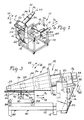
- Figure 1 is a isometric view of an apparatus according to the present invention with a mandrel in a first, or raised, position.
- Figure 2 is another isometric view of the apparatus of Figure 1 with a traffic cone mounted on the mandrel in the first position.
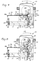
- Figure 3 is a side view of a portion of the apparatus of Figures 1 and 2 with the mandrel lowered to a second position spaced from a platform in a first, or lowered position, and supporting a pair of reflective sleeves.
- Figure 4 is a front view of a portion of the apparatus of Figures 1-3 with the platform raised to a second position to place the traffic cone in contact with the reflective sleeves and with the reflective sleeves partially applied to the traffic cone.
- Figure 5 is a front view of the portion of the apparatus shown in Figure 4 with the reflective sleeves applied to the traffic cone and the platform lowered to its first position.
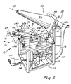
- Figure 6 is an isometric view of a portion of the apparatus of Figures 1-5 with the reflective sleeves applied to the traffic cone and the mandrel raised to its first position.
- Figure 7 is a plan view of a traffic cone with the reflective sleeves applied and removed from the apparatus of Figures 1-6.
- Figure 8 is a schematic representation of a pneumatic circuit for controlling the apparatus of this invention.
- the apparatus 10 comprises frame 12 for supporting the remainder of the apparatus.
- Platform 14 is horizontally mounted on the frame and will explained in greater detail hereinafter.
- Upwardly extending brackets 16 and 18 are mounted on the back edge of frame 12.
- Rod 20 extends between brackets 16 and 18 and is pivotally mounted thereon.
- Double acting first pneumatic cylinder 22 is connected at one end to frame 12 and the shaft thereof is connected by crank arm 24 to rod 20.
- Pneumatic motor 26 is mounted on rod 20.
- Bearing 30 is mounted on motor 26.
- Mandrel 32 includes longitudinal axis 33 and is rotatively supported by bearing 30 and connected to motor 26 to extend over platform 14.
- Mandrel 32 includes stationary portion 34 and adjustable portion 36 which is capable of reciprocal movement along axis 33 with respect to the stationary portion.
- the adjustable portion is biased by a spring or the like (not shown) outwardly from the stationary portion with sufficient force to maintain the position shown in Figure 1.
- Extension of the shaft of pneumatic cylinder 22 in direction 38 will cause rotation of rod 20, motor 26, bearing 30 and mandrel 32 in direction 40 about an axis 41 extending through rod 20 and generally perpendicular to the longitudinal axis 33 of the mandrel.
- Retraction of the shaft in opposite direction 42 will cause rotation of rod 20 and mandrel 32 in opposite rotational direction 44 about axis 41.
- traffic cone 50 includes base 52 and upright member 54, both shown generally frusto conical in shape, although the present invention may also be employed with traffic cones having a generally cylindrical upright member and therefore would require a generally cylindrical mandrel.
- traffic cone 50 is constructed of a monolithic molded polymeric material such as plasticized polyvinyl chloride or polyolefins such as polyethylene.
- the following are examples of commercially available traffic cones which may be used with the present invention: Model 28 PVCS available from Work Area Protection Corp. of St. Charles, Illinois; Model TC-28FL available from Service and Materials Co. of Elwood, Indiana; Model 2850-7 available from the Lakeside Plastics Inc. of Oshkosh, Wisconsin.
- Traffic cone 50 may be mounted on the apparatus by mandrel 32 by sliding the traffic cone on the mandrel until the interior of the traffic cone encounters stationary portion 34.
- stationary portion 34 is adapted to frictionally grip traffic cone 50 to secure it thereon.
- a concentric ring 56 of Safety-Walk tm brand sheeting available from Minnesota Mining and Manufacturing Co. of St. Paul, Minnesota may be adhered to the stationary portion for gripping the traffic cone when pushed onto the mandrel. The frictional sheeting provides sufficient force to hold the traffic cone in position while the reflective sleeves are applied, yet permits easy manual removal.
- Both portions 34, 36 of mandrel 32 are tapered at the nominal taper of the traffic cone to be used with the apparatus.
- adjustable portion 36 is biased to an extreme position away from stationary portion 34, as shown in Figure 1. Due to the large tolerances inherent in the manufacture of traffic cones as well as the deformable nature of the polymeric material normally used to construct traffic cones, the internal taper of individual traffic cones may not match the nominal taper of mandrel 32. This results in misplacement of the traffic cone on the mandrel and deformation of the traffic cone in areas that the reflective sleeves are to be applied. In either case, the reflective sleeves may not be accurately or reliably applied to the traffic cone.
- the illustrated mandrel 32 is constructed to accommodate the variations in traffic cones due to the reciprocal movement of adjustable portion 36 with respect to stationary portion 34. If the taper of a particular traffic cone is less than the nominal taper of the mandrel, adjustable portion 36 of the mandrel will be retracted slightly as the traffic cone is slid onto the mandrel and contacts stationary portion 34. If a traffic cone has a taper that is greater than nominal, adjustable portion 36 will be pushed closer to stationary portion 34 of the mandrel.
- the mandrel securely holds the traffic cone in a desired location relative to the platform and each of the portions 34, 36 of mandrel 32 underlay and support the segments of traffic cone 50 on which the reflective sleeves are to be applied.
- a mandrel may be constructed with more than two portions to more closely conform to the actual taper of individual traffic cones. This may also be desirable if more than two reflective sleeves are to be applied to a traffic cone.
- a pair of sleeves 60a and 60b are shown for application to the traffic cone. Although two sleeves are illustrated, the method and apparatus of the present invention are equally adapted to apply one or more than two sleeves to a traffic cone.
- the sleeves although varying in dimensions, each include longitudinal edges 62a, 62b and spaced end edges 64a, 64b, respectively. If the upright member of the traffic cone is frusto conical in shape, then the longitudinal edges of the reflective sleeves will be arcuate and concentric to accommodate the variation in the circumference of the upright member along its length. If the upright member is cylindrical, then the longitudinal edges are linear and parallel and all sleeves would be the same length.
- One major surface of the sleeves includes a reflective material or coating and the opposite major surface is coated with a pressure sensitive adhesive.
- Model Nos. 3840 and 3810 brand reflective sheeting available from Minnesota Mining and Manufacturing Co. of St. Paul, Minnesota are examples of reflective sheeting that may be used with the traffic cones listed above, as well as others, in the process and with the apparatus of this invention.
- the location means includes stops 66.
- the stops contact the longitudinal and end edges of the reflective sleeves 60a, 60b as shown to precisely determine the location of the sleeves with respect to the platform and specifically to align a pair of end edges 64a, 64b of each sleeve along a line 68 as shown in Figure 2.
- a cushion or resilient strip 70 is mounted on the platform to support end edges 64a, 64b of sleeves 60a, 60b as the sleeves are applied to the traffic cone, as will be explained in greater detail hereinafter.
- cushion 70 is mounted within a recessed groove (not shown) formed in the platform so that the upper surface of the cushion is generally flush with the platform.
- Stops 66 may be made adjustable, such by threadedly securing them to the platform and by providing alternate threaded holes (not shown) in the platform so that the stops may be resecured to the platform in different locations to accommodate sleeves of different dimensions. Further, stops 66 may be eccentrically mounted to the platform so that rotation of a stop about the threaded connection enables a finer adjustment in the location of sleeves 60a, 60b with respect to the platform. Alternatively, recesses (not shown) could be formed in the platform for receipt of the reflective sleeves.
- the position of platform 14 relative to frame 12 and mandrel 32 may be adjusted.
- the adjustment of the platform is accomplished by slidingly mounting the platform on rails 72 and 74, enabling movement of the platform in opposite directions 76 and 78 parallel to line 68.
- Platform 14 may be secured in a desired longitudinal position relative to the mandrel by screws 82 which are threadedly engaged with the platform and may be tightened to contact rails 72 and 74.
- screws 84 are provided and threadedly engaged with the platform so that the position of the platform may be adjusted vertically with respect to the frame and secured to rails 72 and 74 in a desired position by screws 84.
- mandrel 32 and traffic cone 50 have been lowered from the first position shown in Figures 1 and 2 to a second position.
- the tangent line 86 of the portion of upright member 54 of traffic cone 50 closest to end edges 64a, 64b of the reflective sleeves 60a, 60b respectively is parallel to and spaced therefrom.
- Longitudinal axis 33 of the mandrel is inclined downwardly with respect to the platform at the angle of taper of the traffic cone. If traffic cone 50 included a cylindrical upright member (not shown), longitudinal axis 33 of the mandrel and tangent line 86 of the traffic cone would be parallel to each other and to the line 68 on the platform.
- Means are provided to shift the platform between first and second positions in order to place the end edge of the reflective sleeve in contact with the traffic cone at the nearest tangent point of the traffic cone.
- the platform may be shifted in any desired manner, in the illustrated embodiment, the platform is rotated about an axis 87 generally parallel to the tangent line 68 of the traffic cone when the traffic cone and the mandrel are in their second position.
- Axis 87 is also generally perpendicular to axis 41 about which the mandrel rotates between its first and second positions.
- one edge 88 of the platform 14 is hingedly mounted to frame 12 to form axis 87.
- Double acting second pneumatic cylinder 90 is mounted with one end mounted on frame 12 and the other end connected to platform 14 spaced from the hinged connection 88.
- second pneumatic cylinder 90 By activating second pneumatic cylinder 90 and extending its shaft in direction 92, platform 14 rotates upwardly in rotational direction 94 from its first position to its second, upper position, shown in Figure 4. Retraction of the shaft of the second pneumatic cylinder 90 in direction 96 will rotate platform 14 in opposite rotational direction 98 back to its first position.
- edges 64a, 64b of the reflective sleeves aligned with line 68 on the platform is determined so that when the platform is rotated to its second position, the edges 64a, 64b and the pressure sensitive adhesive surface of the sleeves are brought into contact with the tangent line 86 of the traffic cone.
- platform 14 may be constructed so that it may be raised vertically, eliminating the hinged connection 88.
- traffic cone 50 is rotated in direction 100 about longitudinal axis 33 of mandrel 32 (which is axially aligned with the longitudinal axis of the traffic cone) by activating motor 26 so as to wind the reflective sleeves 60a, 60b about the traffic cone.
- Reflective sleeves 60a, 60b are preferably constructed so that end edges 64a, 64b of each sleeve overlap slightly when applied to the traffic cone to ensure effective adherence thereto.
- the traffic cone is rotated through 11 ⁇ 4 turns to ensure effective application of the reflective sleeves thereto.
- platform 14 is rotated in direction 98 back to its first position by retracting the shaft of the second pneumatic cylinder 90 in direction 96, as shown in Figure 5.
- mandrel 32 may be shifted back to its first position by retracting the shaft of first pneumatic cylinder 22 in direction 44, as shown in Figure 6.
- motor 26 is again activated so as to quickly rotate the mandrel and traffic cone in opposite rotational direction 102. This returns mandrel 32 and motor 16 to their original positions and acts to loosen or dislodge the traffic cone from the mandrel.
- the traffic cone with reflective sleeves 60a, 60b applied may then be easily removed from the mandrel.
- Figure 7 illustrates a traffic cone with the reflective sleeves in place and ready for use.
- FIG. 8 is a schematic representation of one such pneumatic circuit 112 for activating and controlling the first and second pneumatic cylinders 22 and 90 and the pneumatic motor 26.
- the pneumatic circuit is connected to a source of compressed air (not shown) which may conveniently be regulated to a pressure of approximately 4.1 x 10⁶Pa (60 p.s.i).
- the pneumatic circuit 112 includes portions of pneumatic conduit 114 connecting the various components of the circuit, which also includes time delay 116 (such as a PA-40 tm brand time delay available from Numatics Incorporated of Highland,Michigan) and limit switch 118 (neither shown in any of the previous Figures).
- time delay 116 such as a PA-40 tm brand time delay available from Numatics Incorporated of Highland,Michigan
- limit switch 118 either shown in any of the previous Figures.
- the operator of the apparatus depresses foot switch 110, which activates first pneumatic cylinder 22 to shift the mandrel from its first position to its second position.
- the limit switch 118 is mounted on the frame adjacent the brackets 16 and 18.
- the location of the second position of the mandrel is determined by an adjustable screw (not shown) mounted on the mandrel so as to come in contact with limit switch 118 as the mandrel moves in rotational direction 40 and thereby interrupt the supply of compressed air to first pneumatic cylinder 22 and prevent further movement of the mandrel.
- the flow of the compressed air to second pneumatic cylinder 90 is regulated so that the movement of the platform from its first to its second position is achieved only after the mandrel and traffic cone have achieved their second position.
- a second time delay could be utilized in conjunction with foot switch 110 to control movement of the platform.
- time delay 116 initiates the activation of motor 26 in rotational direction 100 only after the platform reaches its second position and places the traffic cone in contact with the pressure sensitive adhesive surface of the reflective sleeves.
- removal of the operators foot from foot switch 110 reactivates the first and the second pneumatic cylinders 22 and 90, respectively, to return the mandrel and the platform to their respective first positions.
- the motor 26 is likewise activated to rotate the mandrel in rotational direction 102, which returns the motor to its initial position. After removal of the traffic cone, the apparatus is in position for receipt of a new traffic cone and reflective sleeves.
- electrical or other known power and control devices may be substituted for the pneumatic devices and pneumatic circuit discussed herein, if desired.
Description
- The present invention relates to methods and apparatus for adhesively applying a reflective sleeve to a traffic cone.
- It has been known in the past to apply a sleeve of reflective material to a traffic cone. For the purposes of this invention, the term "traffic cone" includes, but is not limited to, bodies integrally formed from a flexible polymeric material and having a base portion for supporting an upright, generally conical or cylindrical member.
- In the case of traffic cones, it is desirable to adhesively apply reflectorized sheeting material to the extetior of the upright member in order to enhance the visibility of the traffic cone at night or other times of poor visibility. Application of reflective sleeves to a traffic cone has become even more important recently as the latest edition of the Manual on Uniform Traffic Devices (Section 6C-3 Cone design) promulgated by the Federal Highway Administration (the contents of which are incorporated herein by reference) requires that traffic cones for use on freeways be at least 71 cm (28 inches) in height and if utilized at night, must include two reflective bands 7.62 cm (3 inches) in width, one placed a maximum of 5.08 cm (2 inches) from the top of the traffic cone and the other band spaced a maximum of 15.28 cm (6 inches) from the first band. Alternatively, a 15.28 cm (6 inch) wide reflective band may be placed nominally 7.62 cm (3 inches) from the top of the traffic cone and a 10.08 cm (4 inch) wide reflective sleeve placed two inches below the six inch band. Preferably, the reflective bands must be located within a tolerance of ± 0.32 cm (0.125 inch). Such reflective sheeting may be applied manually, but such a process is slow and therefore expensive and requires considerable skill if accuracy is desired.
- U.K. Patent No. 2,096,214 A entitled "Portable Road Markers", commonly assigned to the assignee of the present invention, discloses a method and apparatus for applying a narrow pressure sensitive adhesive tape having a reflective surface opposite the adhesive surface, to a traffic cone or "bollard". The method provides for rotating the tape applying apparatus relative to the traffic cone and means for severing the tape when a sufficient length has been applied to the traffic cone. Means are also provided so that the traffic cone and the tape applying apparatus may be axially shifted relative to each other so that the tape may be applied in a generally helical fashion, although it is contemplated that the tape may be applied in one or more concentric bands. On page 2, lines 44-79, the U.K. '214 patent discusses the difficulties in applying a preformed adjustable sleeve of adhesively secured reflective material to a precise location on a traffic cone.
- Therefore, it would be desirable to provide a method and apparatus for quickly and accurately applying one or more reflective sleeves to a traffic cone.
- According to one aspect of the present invention there is provided an apparatus for applying a reflective sleeve having spaced end edges to a traffic cone, comprising:
a frame,
a mandrel having a longitudinal axis mounted on said frame for receiving the traffic cone and including means for securing the traffic cone on said mandrel, and
means mounted on said frame for rotating said mandrel about said longitudinal axis to wind the sleeve onto the traffic cone characterised by:
a platform mounted on said frame for supporting the reflective sleeve with a pressure sensitive adhesive surface of the reflective sleeve exposed;
means mounted on said frame for shifting said mandrel with the traffic cone secured thereon between a first position and a second position so that a tangent line of the traffic cone nearest to said platform is parallel to and spaced from an end edge of the sleeve; and
means mounted on said frame for shifting said platform between a first position to a second position with said mandrel in said second position to place the pressure sensitive adhesive surface of adhesive sleeve along said end edge thereof in contact with the traffic cone at the nearest tangent line. - According to a second aspect of the present invention there is provided a method for applying a reflective sleeve onto a traffic cone, comprising the steps of:
providing a traffic cone;
providing a reflective sleeve having one major surface coated with a pressure sensitive and having spaced end edges;
providing a frame,
providing a mandrel having a longitudinal axis mounted on said frame for receiving the traffic cone and including means for securing the traffic cone on said mandrel, and
rotating said mandrel about said longitudinal axis to wind the sleeve onto the traffic cone characterised by:
providing a platform mounted on said frame for supporting the reflective sleeve with a pressure sensitive adhesive surface of the reflective sleeve exposed;
shifting said mandrel with the traffic cone secured thereon between a first position and a second position so that a tangent line of the traffic cone nearest to said platform is parallel to and spaced from an end edge of the sleeve; and
shifting said platform between a first position to a second position with said mandrel in said second position to place the pressure sensitive adhesive surface of adhesive sleeve along said end edge thereof in contact with the traffic cone at the nearest tangent line. - The present invention will be further described with reference to the accompanying drawing wherein like reference numerals refer to like parts in the several views, and wherein:
- Figure 1 is a isometric view of an apparatus according to the present invention with a mandrel in a first, or raised, position.
- Figure 2 is another isometric view of the apparatus of Figure 1 with a traffic cone mounted on the mandrel in the first position.
- Figure 3 is a side view of a portion of the apparatus of Figures 1 and 2 with the mandrel lowered to a second position spaced from a platform in a first, or lowered position, and supporting a pair of reflective sleeves.
- Figure 4 is a front view of a portion of the apparatus of Figures 1-3 with the platform raised to a second position to place the traffic cone in contact with the reflective sleeves and with the reflective sleeves partially applied to the traffic cone.
- Figure 5 is a front view of the portion of the apparatus shown in Figure 4 with the reflective sleeves applied to the traffic cone and the platform lowered to its first position.
- Figure 6 is an isometric view of a portion of the apparatus of Figures 1-5 with the reflective sleeves applied to the traffic cone and the mandrel raised to its first position.
- Figure 7 is a plan view of a traffic cone with the reflective sleeves applied and removed from the apparatus of Figures 1-6.
- Figure 8 is a schematic representation of a pneumatic circuit for controlling the apparatus of this invention.
- Referring now to the drawing, there is shown apparatus according to the present invention generally designated by the
reference numeral 10. Generally, theapparatus 10 comprisesframe 12 for supporting the remainder of the apparatus.Platform 14 is horizontally mounted on the frame and will explained in greater detail hereinafter. Upwardly extendingbrackets frame 12.Rod 20 extends betweenbrackets pneumatic cylinder 22 is connected at one end toframe 12 and the shaft thereof is connected bycrank arm 24 torod 20.Pneumatic motor 26 is mounted onrod 20.Bearing 30 is mounted onmotor 26. Mandrel 32 includeslongitudinal axis 33 and is rotatively supported by bearing 30 and connected tomotor 26 to extend overplatform 14. Mandrel 32 includesstationary portion 34 andadjustable portion 36 which is capable of reciprocal movement alongaxis 33 with respect to the stationary portion. The adjustable portion is biased by a spring or the like (not shown) outwardly from the stationary portion with sufficient force to maintain the position shown in Figure 1. Extension of the shaft ofpneumatic cylinder 22 indirection 38 will cause rotation ofrod 20,motor 26, bearing 30 andmandrel 32 indirection 40 about anaxis 41 extending throughrod 20 and generally perpendicular to thelongitudinal axis 33 of the mandrel. Retraction of the shaft in opposite direction 42 will cause rotation ofrod 20 andmandrel 32 in oppositerotational direction 44 aboutaxis 41. - As is shown in Figure 2,
traffic cone 50 includesbase 52 andupright member 54, both shown generally frusto conical in shape, although the present invention may also be employed with traffic cones having a generally cylindrical upright member and therefore would require a generally cylindrical mandrel. Preferably,traffic cone 50 is constructed of a monolithic molded polymeric material such as plasticized polyvinyl chloride or polyolefins such as polyethylene. The following are examples of commercially available traffic cones which may be used with the present invention: Model 28 PVCS available from Work Area Protection Corp. of St. Charles, Illinois; Model TC-28FL available from Service and Materials Co. of Elwood, Indiana; Model 2850-7 available from the Lakeside Plastics Inc. of Oshkosh, Wisconsin. -
Traffic cone 50 may be mounted on the apparatus bymandrel 32 by sliding the traffic cone on the mandrel until the interior of the traffic cone encountersstationary portion 34. Preferably,stationary portion 34 is adapted to frictionallygrip traffic cone 50 to secure it thereon. For instance, aconcentric ring 56 of Safety-Walktm brand sheeting available from Minnesota Mining and Manufacturing Co. of St. Paul, Minnesota may be adhered to the stationary portion for gripping the traffic cone when pushed onto the mandrel. The frictional sheeting provides sufficient force to hold the traffic cone in position while the reflective sleeves are applied, yet permits easy manual removal. - Both
portions mandrel 32 are tapered at the nominal taper of the traffic cone to be used with the apparatus. When a traffic cone is not mounted on the mandrel,adjustable portion 36 is biased to an extreme position away fromstationary portion 34, as shown in Figure 1. Due to the large tolerances inherent in the manufacture of traffic cones as well as the deformable nature of the polymeric material normally used to construct traffic cones, the internal taper of individual traffic cones may not match the nominal taper ofmandrel 32. This results in misplacement of the traffic cone on the mandrel and deformation of the traffic cone in areas that the reflective sleeves are to be applied. In either case, the reflective sleeves may not be accurately or reliably applied to the traffic cone. - The illustrated
mandrel 32 is constructed to accommodate the variations in traffic cones due to the reciprocal movement ofadjustable portion 36 with respect tostationary portion 34. If the taper of a particular traffic cone is less than the nominal taper of the mandrel,adjustable portion 36 of the mandrel will be retracted slightly as the traffic cone is slid onto the mandrel and contactsstationary portion 34. If a traffic cone has a taper that is greater than nominal,adjustable portion 36 will be pushed closer tostationary portion 34 of the mandrel. - In either of the above situations, the mandrel securely holds the traffic cone in a desired location relative to the platform and each of the
portions mandrel 32 underlay and support the segments oftraffic cone 50 on which the reflective sleeves are to be applied. Of course, a mandrel may be constructed with more than two portions to more closely conform to the actual taper of individual traffic cones. This may also be desirable if more than two reflective sleeves are to be applied to a traffic cone. -
Platform 14 is also shown in more detail in Figure 2. A pair ofsleeves 60a and 60b are shown for application to the traffic cone. Although two sleeves are illustrated, the method and apparatus of the present invention are equally adapted to apply one or more than two sleeves to a traffic cone. The sleeves, although varying in dimensions, each includelongitudinal edges 62a, 62b and spacedend edges 64a, 64b, respectively. If the upright member of the traffic cone is frusto conical in shape, then the longitudinal edges of the reflective sleeves will be arcuate and concentric to accommodate the variation in the circumference of the upright member along its length. If the upright member is cylindrical, then the longitudinal edges are linear and parallel and all sleeves would be the same length. - One major surface of the sleeves includes a reflective material or coating and the opposite major surface is coated with a pressure sensitive adhesive. Model Nos. 3840 and 3810 brand reflective sheeting available from Minnesota Mining and Manufacturing Co. of St. Paul, Minnesota are examples of reflective sheeting that may be used with the traffic cones listed above, as well as others, in the process and with the apparatus of this invention.
- Means are provided to precisely locate the sleeves with respect to the platform. In the illustrated embodiment, the location means includes stops 66. The stops contact the longitudinal and end edges of the
reflective sleeves 60a, 60b as shown to precisely determine the location of the sleeves with respect to the platform and specifically to align a pair ofend edges 64a, 64b of each sleeve along aline 68 as shown in Figure 2. Preferably, a cushion orresilient strip 70 is mounted on the platform to supportend edges 64a, 64b ofsleeves 60a, 60b as the sleeves are applied to the traffic cone, as will be explained in greater detail hereinafter. Conveniently,cushion 70 is mounted within a recessed groove (not shown) formed in the platform so that the upper surface of the cushion is generally flush with the platform. -
Stops 66 may be made adjustable, such by threadedly securing them to the platform and by providing alternate threaded holes (not shown) in the platform so that the stops may be resecured to the platform in different locations to accommodate sleeves of different dimensions. Further, stops 66 may be eccentrically mounted to the platform so that rotation of a stop about the threaded connection enables a finer adjustment in the location ofsleeves 60a, 60b with respect to the platform. Alternatively, recesses (not shown) could be formed in the platform for receipt of the reflective sleeves. - Further, the position of
platform 14 relative to frame 12 andmandrel 32 may be adjusted. In the illustrated embodiment, the adjustment of the platform is accomplished by slidingly mounting the platform onrails opposite directions line 68.Platform 14 may be secured in a desired longitudinal position relative to the mandrel byscrews 82 which are threadedly engaged with the platform and may be tightened to contactrails rails - In Figure 3,
mandrel 32 andtraffic cone 50 have been lowered from the first position shown in Figures 1 and 2 to a second position. In the second position, thetangent line 86 of the portion ofupright member 54 oftraffic cone 50 closest to endedges 64a, 64b of thereflective sleeves 60a, 60b respectively, is parallel to and spaced therefrom.Longitudinal axis 33 of the mandrel is inclined downwardly with respect to the platform at the angle of taper of the traffic cone. Iftraffic cone 50 included a cylindrical upright member (not shown),longitudinal axis 33 of the mandrel andtangent line 86 of the traffic cone would be parallel to each other and to theline 68 on the platform. - Means are provided to shift the platform between first and second positions in order to place the end edge of the reflective sleeve in contact with the traffic cone at the nearest tangent point of the traffic cone. Although the platform may be shifted in any desired manner, in the illustrated embodiment, the platform is rotated about an
axis 87 generally parallel to thetangent line 68 of the traffic cone when the traffic cone and the mandrel are in their second position.Axis 87 is also generally perpendicular toaxis 41 about which the mandrel rotates between its first and second positions. - As shown, one
edge 88 of theplatform 14 is hingedly mounted to frame 12 to formaxis 87. Double acting secondpneumatic cylinder 90 is mounted with one end mounted onframe 12 and the other end connected toplatform 14 spaced from the hingedconnection 88. By activating secondpneumatic cylinder 90 and extending its shaft indirection 92,platform 14 rotates upwardly inrotational direction 94 from its first position to its second, upper position, shown in Figure 4. Retraction of the shaft of the secondpneumatic cylinder 90 indirection 96 will rotateplatform 14 in oppositerotational direction 98 back to its first position. The location ofedges 64a, 64b of the reflective sleeves aligned withline 68 on the platform is determined so that when the platform is rotated to its second position, theedges 64a, 64b and the pressure sensitive adhesive surface of the sleeves are brought into contact with thetangent line 86 of the traffic cone. Of course,platform 14 may be constructed so that it may be raised vertically, eliminating the hingedconnection 88. - The relative motion of
mandrel 32 supportingtraffic cone 50 andplatform 14 supportingreflective sleeves 60a, 60b places the traffic cone in contact with the reflective sleeves without disturbing the position of the sleeves. If the rotative motion ofmandrel 32 indirection 40 is allowed to placetraffic cone 50 in contact with the reflective sleeves, the traffic cone will first encounter theupper sleeve 60a. Continued rotative motion of the traffic cone required to fully contact the bothsleeves 60a, 60b will tend to pull the sleeves indirection 76, with obvious disadvantageous results for the accuracy in placement of the reflective sleeves on the traffic cone. - As is then also shown in Figure 4, once the traffic cone is placed in contact with the reflective sleeves,
traffic cone 50 is rotated indirection 100 aboutlongitudinal axis 33 of mandrel 32 (which is axially aligned with the longitudinal axis of the traffic cone) by activatingmotor 26 so as to wind thereflective sleeves 60a, 60b about the traffic cone.Reflective sleeves 60a, 60b are preferably constructed so that end edges 64a, 64b of each sleeve overlap slightly when applied to the traffic cone to ensure effective adherence thereto. Preferably, the traffic cone is rotated through 1¼ turns to ensure effective application of the reflective sleeves thereto. Afterreflective sleeves 60a, 60b are wound upontraffic cone 50,platform 14 is rotated indirection 98 back to its first position by retracting the shaft of the secondpneumatic cylinder 90 indirection 96, as shown in Figure 5. - With
platform 14 disengaged,mandrel 32 may be shifted back to its first position by retracting the shaft of firstpneumatic cylinder 22 indirection 44, as shown in Figure 6. During the process of raisingmandrel 32 to its first position,motor 26 is again activated so as to quickly rotate the mandrel and traffic cone in oppositerotational direction 102. This returnsmandrel 32 andmotor 16 to their original positions and acts to loosen or dislodge the traffic cone from the mandrel. The traffic cone withreflective sleeves 60a, 60b applied may then be easily removed from the mandrel. Figure 7 illustrates a traffic cone with the reflective sleeves in place and ready for use. - Although each of the steps of the present invention may be controlled manually, in the preferred embodiment of the invention, the motion and timing of the mandrel and platform are automatically controlled by a pneumatic circuit and activated by
foot switch 110, shown in Figures 1 and 2. Figure 8 is a schematic representation of one suchpneumatic circuit 112 for activating and controlling the first and secondpneumatic cylinders pneumatic motor 26. The pneumatic circuit is connected to a source of compressed air (not shown) which may conveniently be regulated to a pressure of approximately 4.1 x 10⁶Pa (60 p.s.i). Thepneumatic circuit 112 includes portions ofpneumatic conduit 114 connecting the various components of the circuit, which also includes time delay 116 (such as a PA-40tm brand time delay available from Numatics Incorporated of Highland,Michigan) and limit switch 118 (neither shown in any of the previous Figures). - In operation, the operator of the apparatus depresses
foot switch 110, which activates firstpneumatic cylinder 22 to shift the mandrel from its first position to its second position. The limit switch 118 is mounted on the frame adjacent thebrackets rotational direction 40 and thereby interrupt the supply of compressed air to firstpneumatic cylinder 22 and prevent further movement of the mandrel. The flow of the compressed air to secondpneumatic cylinder 90 is regulated so that the movement of the platform from its first to its second position is achieved only after the mandrel and traffic cone have achieved their second position. Alternatively, a second time delay could be utilized in conjunction withfoot switch 110 to control movement of the platform. - Further,
time delay 116 initiates the activation ofmotor 26 inrotational direction 100 only after the platform reaches its second position and places the traffic cone in contact with the pressure sensitive adhesive surface of the reflective sleeves. After the application of the reflective sleeves to the traffic cones, removal of the operators foot fromfoot switch 110 reactivates the first and the secondpneumatic cylinders motor 26 is likewise activated to rotate the mandrel inrotational direction 102, which returns the motor to its initial position. After removal of the traffic cone, the apparatus is in position for receipt of a new traffic cone and reflective sleeves. Of course, electrical or other known power and control devices may be substituted for the pneumatic devices and pneumatic circuit discussed herein, if desired. - The present invention has now been described with reference to an embodiment thereof. It will be apparent to those skilled in the art that many changes can be made in the embodiments described without departing from the scope of the present invention. Thus, the scope of the present invention should not be limited to the structures described in this application, but only by structures described by the language of the claims and the equivalents of those structures.
Claims (8)
- Apparatus (10) for applying a reflective sleeve (60a) having spaced end edges to a traffic cone (50), comprising:
a frame (12),
a mandrel (32) having a longitudinal axis mounted on said frame (12) for receiving the traffic cone (50) and including means for securing the traffic cone on said mandrel, and
means mounted on said frame (12) for rotating said mandrel (32) about said longitudinal axis to wind the sleeve (60a) onto the traffic cone (50) characterised by:
a platform (14) mounted on said frame for supporting the reflective sleeve (60a) with a pressure sensitive adhesive surface of the reflective sleeve exposed;
means mounted on said frame for shifting said mandrel (32) with the traffic cone (50) secured thereon between a first position and a second position so that a tangent line of the traffic cone nearest to said platform is parallel to and spaced from an end edge of the sleeve; and
means mounted on said frame (12) for shifting said platform (14) between a first position to a second position with said mandrel (32) in said second position to place the pressure sensitive adhesive surface of adhesive sleeve (60a) along said end edge thereof in contact with the traffic cone (50) at the nearest tangent line. - The apparatus (10) of claim 1, further characterized by comprising means for delaying the shifting of said platform (14) from said first position to said second position until said mandrel (32) is in said second position.
- The apparatus (10) of claim 1, further characterized in that said mandrel is rotated between said first position and said second position,
- The apparatus of claim 3, further characterized in that said platform (14) is rotated between said first position and said second position.
- The apparatus (10) of claim 1, further characterized in that said mandrel (32) includes a stationary portion (34) and an adjustable portion (36) mounted on said stationary portion and adapted for reciprocal movement with respect to said stationary portion, and including means for resiliently urging said adjustable portion away from said stationary portion, said stationary portion and said adjustable portion each having a tapered exterior adapted for receipt of the traffic cone (50), wherein said adjustable portion (36) is shifted towards said stationary portion (34) when the traffic cone is mounted on said mandrel so that the traffic cone is securely mounted thereon and supported when the reflective sleeve (60a) is applied.
- The apparatus (10) of claim 1, further characterized in that said platform (14) includes means for locating an edge of the reflective sleeve (60a) on said platform with respect to the nearest tangent line of the traffic cone (50) when said platform (14) and said mandrel (32) are in their second positions.
- A method for applying a reflective sleeve (60a) onto a traffic cone (50), comprising the steps of:
providing a traffic cone (50);
providing a reflective sleeve (60a) having one major surface coated with a pressure sensitive adhesive and having spaced end edges (64a);
providing a frame (12),
providing a mandrel (12) having a longitudinal axis mounted on said frame (12) for receiving the traffic cone (50) and including means for securing the traffic cone on said mandrel, and
rotating said mandrel (12) about said longitudinal axis to wind the sleeve (60a) onto the traffic cone (50) characterised by:
providing a platform (14) mounted on said frame (12) for supporting the reflective sleeve (60a) with a pressure sensitive adhesive surface of the reflective sleeve exposed;
shifting said mandrel (12) with the traffic cone (50) secured thereon between a first position and a second position so that a tangent line of the traffic cone nearest to said platform is parallel to and spaced from an end edge of the sleeve; and
shifting said platform (14) between a first position to a second position with said mandrel (12) in said second position to place the pressure sensitive adhesive surface of adhesive sleeve (60a) along said end edge thereof in contact with the traffic cone (50) at the nearest tangent line. - The method of claim 7, further characterized by the steps of:(a) providing a second reflective sleeve (60b) having a pressure sensitive adhesive surface; and(b) aligning an end edge (64b) of the second sleeve (60b) with the end edge (64a) of the first sleeve (60a);(c) whereby the traffic cone (50) will contact both sleeves (60a, 60b) simultaneously and both sleeves will be wound upon the traffic cone when the traffic cone is rotated.
Applications Claiming Priority (2)
| Application Number | Priority Date | Filing Date | Title |
|---|---|---|---|
| US371919 | 1989-06-27 | ||
| US07/371,919 US5047107A (en) | 1989-06-27 | 1989-06-27 | Method and apparatus for applying a reflective sleeve to a traffic cone |
Publications (3)
| Publication Number | Publication Date |
|---|---|
| EP0405880A2 EP0405880A2 (en) | 1991-01-02 |
| EP0405880A3 EP0405880A3 (en) | 1991-01-30 |
| EP0405880B1 true EP0405880B1 (en) | 1993-04-21 |
Family
ID=23465957
Family Applications (1)
| Application Number | Title | Priority Date | Filing Date |
|---|---|---|---|
| EP90306913A Expired - Lifetime EP0405880B1 (en) | 1989-06-27 | 1990-06-25 | Method and apparatus for applying a reflective sleeve to a traffic cone |
Country Status (8)
| Country | Link |
|---|---|
| US (1) | US5047107A (en) |
| EP (1) | EP0405880B1 (en) |
| JP (1) | JP2875858B2 (en) |
| AU (1) | AU624719B2 (en) |
| CA (1) | CA2018860A1 (en) |
| DE (1) | DE69001398T2 (en) |
| ES (1) | ES2040057T3 (en) |
| IE (1) | IE64027B1 (en) |
Cited By (1)
| Publication number | Priority date | Publication date | Assignee | Title |
|---|---|---|---|---|
| CN105730802A (en) * | 2016-04-29 | 2016-07-06 | 福建欣弘机电设备有限公司 | Paper sticking machine for cup |
Families Citing this family (11)
| Publication number | Priority date | Publication date | Assignee | Title |
|---|---|---|---|---|
| US5451287A (en) * | 1993-12-17 | 1995-09-19 | Minnesota Mining And Manufacturing Company | Machine for wrapping tubular markers with a reflective material |
| US5565055A (en) * | 1995-05-08 | 1996-10-15 | Avery Dennison Corporation | Decoration of articles |
| US5805338A (en) * | 1996-04-10 | 1998-09-08 | Minnesota Minning And Manufacturing Company | Pillowed flexible cube-corner sheeting and methods of manufacture |
| AU6775698A (en) * | 1997-11-12 | 1999-05-31 | Minnesota Mining And Manufacturing Company | Multicolored retroreflective banded sleeve for a traffic device and method of making |
| US7165592B1 (en) * | 2002-12-10 | 2007-01-23 | Berran Industrial Group, Inc. | Strip material applicator apparatus |
| NL1025330C2 (en) * | 2004-01-27 | 2005-08-01 | Theodorus Carolus Josep Simons | Device and method for picking up a pawn. |
| US7306398B2 (en) * | 2005-01-06 | 2007-12-11 | Doran Jr John Terrence | Highway marker transfer vehicle |
| US8389117B2 (en) * | 2008-10-30 | 2013-03-05 | Eastman Chemical Company | Hot melt adhesives for roll-applied labels |
| WO2010099314A1 (en) * | 2009-02-25 | 2010-09-02 | L . B. Foster Company | Composite rail joint end post |
| US8747017B2 (en) * | 2011-04-20 | 2014-06-10 | Stefan Albrecht Dag | Resilient inflatable delineators |
| KR102440145B1 (en) * | 2021-06-30 | 2022-09-05 | 주식회사 기성이엔지 | Labacon Alignment Device in Labacon Horizontal Load Type Installation and Recovery Unit |
Family Cites Families (25)
| Publication number | Priority date | Publication date | Assignee | Title |
|---|---|---|---|---|
| US2081911A (en) * | 1932-12-03 | 1937-06-01 | Burt Co Ltd F N | Applying machine |
| US3455758A (en) * | 1965-12-02 | 1969-07-15 | Horizons Research Inc | Method and apparatus for the manufacture of plastic belts |
| US3616055A (en) * | 1969-05-16 | 1971-10-26 | David H Mages | Optical plate mounter |
| SE351575B (en) * | 1970-09-02 | 1972-12-04 | Polytype Ag | |
| US3709112A (en) * | 1970-09-10 | 1973-01-09 | G Ebinger | Guide picket |
| US3768383A (en) * | 1970-11-03 | 1973-10-30 | Tucker Ass Inc | Directional marker device for automobile roadbeds |
| US3952690A (en) * | 1972-01-18 | 1976-04-27 | Flexicade Ltd. | Highway barricade |
| US3920348A (en) * | 1974-09-09 | 1975-11-18 | Olympic Machine Inc | Traffic lane indicator |
| US3963362A (en) * | 1974-11-27 | 1976-06-15 | Carlisle Corporation | Road marker |
| FR2406696A1 (en) * | 1977-10-19 | 1979-05-18 | Electroformage Plastiques Cie | Tubular marker post for highway - has fascia panel forming reflective windows and locked in place by clip-on cap |
| US4123181A (en) * | 1977-12-02 | 1978-10-31 | Astro Optics Corporation | Roadside barrier marker system |
| US4111581A (en) * | 1978-01-03 | 1978-09-05 | Auriemma Robert S | Highway marker |
| US4197807A (en) * | 1978-06-23 | 1980-04-15 | Campbell Bruce E | Collapsible traffic cone marker |
| US4245922A (en) * | 1979-04-02 | 1981-01-20 | Auriemma Robert S | Traffic delineator post |
| US4221498A (en) * | 1979-05-07 | 1980-09-09 | Astro Optics Corporation | Roadside barrier reflector |
| US4343567A (en) * | 1980-02-27 | 1982-08-10 | Robert D. Cunningham | Self-erecting roadway marking post |
| GB2139116B (en) * | 1980-10-17 | 1985-08-29 | Minnesota Mining & Mfg | Portable road markers |
| GB2096214B (en) * | 1980-10-17 | 1985-08-21 | Minnesota Mining & Mfg | Portable road markers |
| FR2500505A1 (en) * | 1981-02-24 | 1982-08-27 | Pinoteau Lucien | Reflecting road beacon embedded in ground - defines traffic islands from carriageways and has semi rigid rubber body resilient to shock impacts |
| US4571118A (en) * | 1984-01-20 | 1986-02-18 | Carsonite International Corporation | Simulated tubular highway safety device |
| FR2516564A1 (en) * | 1981-11-19 | 1983-05-20 | Cormier Bernard | Retroreflective signal for traffic route edges - has cylindrical surface to reflect light from any direction |
| US4397710A (en) * | 1982-01-22 | 1983-08-09 | The Meyercord Co. | Machine for applying indicia to tapered or straight cylindrical articles |
| GB2140547A (en) * | 1983-04-22 | 1984-11-28 | John Roach Bichard | Traffic warning signal cone with flashing light |
| JPS60260261A (en) * | 1984-06-07 | 1985-12-23 | Fuji Xerox Co Ltd | Circuit for conference telephone set |
| US4573763A (en) * | 1984-12-18 | 1986-03-04 | Eagle Industries, Inc. | Three-dimensional flexible reflectors |
-
1989
- 1989-06-27 US US07/371,919 patent/US5047107A/en not_active Expired - Fee Related
-
1990
- 1990-06-08 IE IE206390A patent/IE64027B1/en not_active IP Right Cessation
- 1990-06-13 AU AU57105/90A patent/AU624719B2/en not_active Ceased
- 1990-06-13 CA CA002018860A patent/CA2018860A1/en not_active Abandoned
- 1990-06-25 EP EP90306913A patent/EP0405880B1/en not_active Expired - Lifetime
- 1990-06-25 DE DE90306913T patent/DE69001398T2/en not_active Expired - Fee Related
- 1990-06-25 ES ES199090306913T patent/ES2040057T3/en not_active Expired - Lifetime
- 1990-06-26 JP JP2165888A patent/JP2875858B2/en not_active Expired - Lifetime
Cited By (1)
| Publication number | Priority date | Publication date | Assignee | Title |
|---|---|---|---|---|
| CN105730802A (en) * | 2016-04-29 | 2016-07-06 | 福建欣弘机电设备有限公司 | Paper sticking machine for cup |
Also Published As
| Publication number | Publication date |
|---|---|
| US5047107A (en) | 1991-09-10 |
| CA2018860A1 (en) | 1990-12-27 |
| DE69001398T2 (en) | 1993-10-21 |
| AU624719B2 (en) | 1992-06-18 |
| JPH0351407A (en) | 1991-03-05 |
| EP0405880A2 (en) | 1991-01-02 |
| IE902063A1 (en) | 1991-01-16 |
| DE69001398D1 (en) | 1993-05-27 |
| IE64027B1 (en) | 1995-06-28 |
| ES2040057T3 (en) | 1993-10-01 |
| JP2875858B2 (en) | 1999-03-31 |
| AU5710590A (en) | 1991-01-03 |
| EP0405880A3 (en) | 1991-01-30 |
Similar Documents
| Publication | Publication Date | Title |
|---|---|---|
| EP0405880B1 (en) | Method and apparatus for applying a reflective sleeve to a traffic cone | |
| US4115172A (en) | Apparatus and method for applying puncture sealant material to a tire | |
| EP0790121A3 (en) | Apparatus for applying an apex filler to a bead ring | |
| EP1112411A4 (en) | Apparatus for retrieving conical roadway warning markers | |
| EP0340147A3 (en) | Apparatus for the manufacture of a pneumatic tire | |
| EP0196521B1 (en) | Bead filler applicator | |
| KR920700896A (en) | Method and apparatus for attaching bead apex | |
| US5330125A (en) | Method and apparatus for formation and holding of a loose starting flap of a replacement paper roll, typically a paper roll in a printing machine roll changer | |
| US4949700A (en) | Ingot support device in slicing apparatus | |
| US6282766B1 (en) | Roll cutter | |
| CA1293142C (en) | Supplementary device for inserting screws by means of a power-driven screw driver | |
| US5451287A (en) | Machine for wrapping tubular markers with a reflective material | |
| CA2140692A1 (en) | Tool Fixture for Abrading Apparatus | |
| US4061525A (en) | Tire bead covering apparatus | |
| US4491162A (en) | Hand held duplicator tool | |
| JP2834487B2 (en) | Tire assembly method | |
| US4722132A (en) | Splicing method for tire sheet material | |
| US4805684A (en) | Tire tread grooving method and apparatus | |
| JPH0737255B2 (en) | Label sticker | |
| CN1071367A (en) | The method and apparatus of the thin plate reshaping of processing | |
| US6557323B1 (en) | Wipe down brush system for overhead stretch wrapper and method of operating the same | |
| US4761195A (en) | Tire building machine server | |
| GB2139116A (en) | Portable road markers | |
| JP2873767B2 (en) | Cutting equipment such as adhesive tape | |
| US4755253A (en) | Splicing apparatus |
Legal Events
| Date | Code | Title | Description |
|---|---|---|---|
| PUAI | Public reference made under article 153(3) epc to a published international application that has entered the european phase |
Free format text: ORIGINAL CODE: 0009012 |
|
| PUAL | Search report despatched |
Free format text: ORIGINAL CODE: 0009013 |
|
| AK | Designated contracting states |
Kind code of ref document: A2 Designated state(s): DE ES FR GB IT SE |
|
| AK | Designated contracting states |
Kind code of ref document: A3 Designated state(s): DE ES FR GB IT SE |
|
| 17P | Request for examination filed |
Effective date: 19910102 |
|
| 17Q | First examination report despatched |
Effective date: 19911203 |
|
| ITF | It: translation for a ep patent filed |
Owner name: BARZANO' E ZANARDO ROMA S.P.A. |
|
| GRAA | (expected) grant |
Free format text: ORIGINAL CODE: 0009210 |
|
| AK | Designated contracting states |
Kind code of ref document: B1 Designated state(s): DE ES FR GB IT SE |
|
| REF | Corresponds to: |
Ref document number: 69001398 Country of ref document: DE Date of ref document: 19930527 |
|
| ET | Fr: translation filed | ||
| ITTA | It: last paid annual fee | ||
| REG | Reference to a national code |
Ref country code: ES Ref legal event code: FG2A Ref document number: 2040057 Country of ref document: ES Kind code of ref document: T3 |
|
| PLBE | No opposition filed within time limit |
Free format text: ORIGINAL CODE: 0009261 |
|
| STAA | Information on the status of an ep patent application or granted ep patent |
Free format text: STATUS: NO OPPOSITION FILED WITHIN TIME LIMIT |
|
| 26N | No opposition filed | ||
| EAL | Se: european patent in force in sweden |
Ref document number: 90306913.6 |
|
| PGFP | Annual fee paid to national office [announced via postgrant information from national office to epo] |
Ref country code: SE Payment date: 19950511 Year of fee payment: 6 |
|
| PGFP | Annual fee paid to national office [announced via postgrant information from national office to epo] |
Ref country code: ES Payment date: 19950612 Year of fee payment: 6 |
|
| PG25 | Lapsed in a contracting state [announced via postgrant information from national office to epo] |
Ref country code: SE Effective date: 19960626 Ref country code: ES Free format text: LAPSE BECAUSE OF EXPIRATION OF PROTECTION Effective date: 19960626 |
|
| EUG | Se: european patent has lapsed |
Ref document number: 90306913.6 |
|
| PGFP | Annual fee paid to national office [announced via postgrant information from national office to epo] |
Ref country code: FR Payment date: 19970521 Year of fee payment: 8 |
|
| PGFP | Annual fee paid to national office [announced via postgrant information from national office to epo] |
Ref country code: DE Payment date: 19970522 Year of fee payment: 8 |
|
| PGFP | Annual fee paid to national office [announced via postgrant information from national office to epo] |
Ref country code: GB Payment date: 19980526 Year of fee payment: 9 |
|
| PG25 | Lapsed in a contracting state [announced via postgrant information from national office to epo] |
Ref country code: FR Free format text: LAPSE BECAUSE OF NON-PAYMENT OF DUE FEES Effective date: 19990226 |
|
| PG25 | Lapsed in a contracting state [announced via postgrant information from national office to epo] |
Ref country code: DE Free format text: LAPSE BECAUSE OF NON-PAYMENT OF DUE FEES Effective date: 19990401 |
|
| REG | Reference to a national code |
Ref country code: FR Ref legal event code: ST |
|
| PG25 | Lapsed in a contracting state [announced via postgrant information from national office to epo] |
Ref country code: GB Free format text: LAPSE BECAUSE OF NON-PAYMENT OF DUE FEES Effective date: 19990625 |
|
| REG | Reference to a national code |
Ref country code: ES Ref legal event code: FD2A Effective date: 19990601 |
|
| GBPC | Gb: european patent ceased through non-payment of renewal fee |
Effective date: 19990625 |
|
| PG25 | Lapsed in a contracting state [announced via postgrant information from national office to epo] |
Ref country code: IT Free format text: LAPSE BECAUSE OF NON-PAYMENT OF DUE FEES Effective date: 20050625 |