EP0404877B1 - Raccord de passage d'alimentation pour dispositif medical implantable - Google Patents
Raccord de passage d'alimentation pour dispositif medical implantable Download PDFInfo
- Publication number
- EP0404877B1 EP0404877B1 EP89910721A EP89910721A EP0404877B1 EP 0404877 B1 EP0404877 B1 EP 0404877B1 EP 89910721 A EP89910721 A EP 89910721A EP 89910721 A EP89910721 A EP 89910721A EP 0404877 B1 EP0404877 B1 EP 0404877B1
- Authority
- EP
- European Patent Office
- Prior art keywords
- lead
- pacemaker
- electrical
- tubular channel
- electrical lead
- Prior art date
- Legal status (The legal status is an assumption and is not a legal conclusion. Google has not performed a legal analysis and makes no representation as to the accuracy of the status listed.)
- Expired - Lifetime
Links
Images
Classifications
-
- H—ELECTRICITY
- H01—ELECTRIC ELEMENTS
- H01R—ELECTRICALLY-CONDUCTIVE CONNECTIONS; STRUCTURAL ASSOCIATIONS OF A PLURALITY OF MUTUALLY-INSULATED ELECTRICAL CONNECTING ELEMENTS; COUPLING DEVICES; CURRENT COLLECTORS
- H01R13/00—Details of coupling devices of the kinds covered by groups H01R12/70 or H01R24/00 - H01R33/00
- H01R13/40—Securing contact members in or to a base or case; Insulating of contact members
- H01R13/405—Securing in non-demountable manner, e.g. moulding, riveting
- H01R13/41—Securing in non-demountable manner, e.g. moulding, riveting by frictional grip in grommet, panel or base
-
- A—HUMAN NECESSITIES
- A61—MEDICAL OR VETERINARY SCIENCE; HYGIENE
- A61N—ELECTROTHERAPY; MAGNETOTHERAPY; RADIATION THERAPY; ULTRASOUND THERAPY
- A61N1/00—Electrotherapy; Circuits therefor
- A61N1/18—Applying electric currents by contact electrodes
- A61N1/32—Applying electric currents by contact electrodes alternating or intermittent currents
- A61N1/36—Applying electric currents by contact electrodes alternating or intermittent currents for stimulation
- A61N1/372—Arrangements in connection with the implantation of stimulators
- A61N1/375—Constructional arrangements, e.g. casings
- A61N1/3752—Details of casing-lead connections
Definitions
- the present invention relates to an electrical connector used with an implantable medical device, such as a pacemaker, for connecting an implantable electrical lead to the electrical circuits within a hermetically sealed housing of the medical device. More particularly, the present invention relates to a feedthrough/connector for use with a sealed implantable pacemaker that combines the connector function with the feedthrough function and that eliminates the need for the cast or other preformed epoxy connector that has heretofore been used on implantable pacemakers.
- Modern pacemakers monitor the activity of a heart and provide a stimulation pulse in the absence of normal heart activity.
- such devices are relatively small, light-weight and implantable.
- pacemakers In order to sense and stimulate the heart, however, such pacemakers must be used with a pacemaker lead --an electrical conductor that carries electrical signals between the heart and the pacemaker.
- the pacemaker lead can be inserted into the heart transvenously through a relatively simple and well-known surgical procedure.
- one end of the lead (designated herein as the "connecting end”) must be electrically and mechanically secured to the pacemaker in a way that provides for a long-term safe and secure, yet detachable, connection.
- Those skilled in the pacemaker art have long sought for a simple, yet reliable and safe, means for making this detachable electrical and mechanical connection between the pacemaker device and the connecting end of the pacemaker lead.
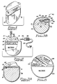
- a pacemaker 10 electrically includes a battery 14 that powers electrical circuits 12.
- the pacemaker electrical circuits 12 and battery 14 are mechanically housed and hermetically sealed in a suitable housing 16.
- this housing or case 16 is shaped to include a flat side or platform 20 to which a suitable epoxy connector 22 can be bonded.
- a platinum wire 24, or other suitable conductive element connects the terminal 18 to a conductive connector block 26 that is fitted within the connector 22.
- a pacemaker lead 28, having a proximal electrode 30, connects to the pacemaker electrical circuits by inserting the proximal electrode 30 into a receiving channel 31 of the connector 22 until the electrode 30 is in contact with the connector block 24.
- a set screw 32 is then securely tightened using a torque wrench 34 to firmly hold the electrode 30 in both mechanical and electrical connection with the connector block 26.
- a septum (not shown) is typically placed over the set screw 32 in order to prevent body fluids from seeping through the set screw hole.
- sealing ribs or ridges 36 on the connecting end of the pacemaker lead are designed to tightly engage the inside edges of the receiving channel 31 in order to prevent any body fluids from entering into the receiving channel 31 once the connecting end of the lead has been pushed into the connector 22.
- prior art connectors 22 are cast in place from epoxy to the platform or header 20 of the pacemaker, or a premolded connector is bonded to the platform 20 using a suitable sealing and bonding agent. Further, once the electrical connection is made from the terminal post 18 to the connector block 26, and the connector is attached to the housing, all remaining voids within the connector 22, not including the receiving channel 31 into which the proximal end of the lead is to be inserted, must be filled with a suitable filler material, such as a two-component epoxy or silicone rubber.
- GB 1 598 793 discloses a case for a medical implant, said case comprising a plastics material substrate defining a closed chamber and a platinum skin fitted over the substrate.
- the case has a socket member defining a bore provided therein allowing electrical connection to be made to the electronic circuits inside the case.
- the bore of the socket member is arranged to receive an electrode lead with an appropriate plug member for electrically contacting the lead to the inside of the bore.
- the present invention provides a feedthrough connector for a pacemaker, or other implantable medical device, that advantageously combines the connector function with the feedthrough function and eliminates the need for the cast epoxy connector previously used on prior art pacemakers. Eliminating the external cast epoxy connector advantageously eliminates the need for septums, setscrews, and the feedthrough terminal and its associated platinum wires and connector blocks, as well as the whole time consuming casting process with its inherent propensity for cosmetic problems.
- the feedthrough/connector of the present invention includes a barrel assembly having an open end and a closed end.
- the open end of the assembly provides an opening into which the connecting end of a pacemaker lead, or other electrical lead, can be inserted.
- the barrel assembly includes metal (conductive) portions separated by ceramic (nonconductive) insulating portions.
- An overlap region of the conductive portions, separated by the nonconductive portion advantageously provides structural strength as well as a capacitor structure. This capacitor helps filter out unwanted electromagnetic interference (EMI) signals from passing through the connector.
- Spring contacts are mounted on the inside of the metal portions and are adapted to make electrical contact with the appropriate electrodes of the pacemaker or other electrical lead when the connecting end of the lead is inserted into the connector.
- the barrel assembly is fitted into an opening in the device housing with the open end being flush with the surface of the housing and the closed end protruding into the housing.
- the outer side of the metal portions are electrically connected to the appropriate electrical circuit within the housing, and the open end of the barrel assembly is welded or otherwise bonded to the device housing so that the inside of the device can be hermetically sealed.
- Releasable lead gripping means are included as part of the barrel assembly to detachably lock and seal the connecting end of the electrical lead in its inserted position inside of the connector.
- Still a further feature of the present invention is to provide a pacemaker that can be smaller than pacemakers of the prior art that perform an equivalent function.
- Yet a further feature of the present invention is to provide a connection system for use with an implantable medical device, such as a pacemaker, that firmly yet detachably locks and seals the connecting end of an electrical lead thereto but that does not require the use of setscrews, septums, or equivalent mechanical securing and sealing devices.
- an implantable medical device such as a pacemaker
- a still further feature of the present invention is to provide a connection system for use with implantable medical devices that is compatible with existing electrical leads, whereby a medical device having the connection system of the present invention may replace a prior art system and still utilize an existing implantable or implanted lead that was used with the prior art system.
- Figs. 1 and 2 have been described previously in connection with the description of the prior art in the Background portion of this application.
- Fig. 3A likewise depicts a prior art pacemaker device.
- Fig. 3A shows the relative size of the device and area therewithin that is hermetically sealed. The sealed area is the shaded area 38.
- the electrical circuits 12 of the pacer are housed in the sealed area 38.
- at least one feedthrough terminal 18 In order to make electrical contact with these circuits 12, at least one feedthrough terminal 18 must pass through the case 16.
- Some type of insulating material 19 must be used with the feedthrough terminal 18 in order to electrically insulate this terminal from the case 16. (A portion of the case 16 typically functions as a return electrode for unipolar pacing.)
- Fig. 3A should be compared to Fig. 3B, where there is shown a simplified side sectional view of a pacemaker 40 incorporating the present invention.
- that portion of the pacemaker that is hermetically sealed is the shaded area 42. This area is enclosed by the case 44 of the pacemaker. As with the prior art device, this sealed area 42 includes the electrical circuits 12 of the pacer.
- a receiving channel 46 protrudes inwardly into the pacer. This channel may conceptually be thought of as an indented channel for it includes an open end 48 flush with the surface of the pacer housing 44 and a closed end 50 within the pacer housing 44, thereby forming, as it were, a long narrow indent within the pacer housing 44.
- the receiving channel 46 is not formed by indenting the pacer housing 44. Nonetheless, for purposes of illustrating those areas of the pacer that are sealed from those areas that are not, it may be helpful to conceptualize the receiving channel as an indented channel.)
- the inside walls 45 of the receiving channel 46 are not included within the sealed areas of the pacemaker 40 for they are open to the outside environment of the pacer through the open end 48.
- the reverse side of the inside walls 45 of the receiving channel 46 (referred to hereafter as the "backside” or "outside” walls of the receiving channel 46) are exposed to the sealed inner portions of the pacemaker.
- a portion 52 of the walls of the receiving channel 46 are made from a conductive material, such as a short 316L stainless tubular section.
- This conductive portion is insulated from the pacer walls 44 by insulating (nonconductive) portions 54 of the walls of the receiving channel 46 which are adjacent the conductive portion.
- these nonconductive portions 54 may be made from short ceramic tubular sections that are hermetically bonded to the conductive portion 52 and the walls of the channel 45.
- any suitable nonconductive material such as an epoxy or polymer substance, could be used to perform this insulating function providing that a suitable hermetic bond is made thereto.
- the backside or outside of the conductive portion 52 is electrically connected to the pacemaker circuits 12 by means of a suitable electrical conductor 56.
- a suitable electrical conductor 56 can be made from any suitable electrically conductive material, not just those types of conductors (such as titanium) that are compatible with exposure to body fluids.
- the conductor 56 should be made from a material that is compatible with the type of material used for the conductive portion 52 of the receiving channel 46 in order to prevent any galvanic or other adverse reactions between dissimilar metals in electrical contact with each other.
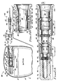
- FIG. 4 a side view of the connecting end 62 of a pacing lead 64 adapted to be inserted into the connector of the present invention, as well as a sectional side view of a lead lock button 70 and sealing/gripping element 103.
- the lead lock button is shown in Fig. 4 in an exploded position from its normal position within the open end of the receiving channel 72 of the connector.
- the lead lock button 70 and sealing/gripping element 103 lock and seal the connecting end 62 of the lead 64 into a receiving channel 72 of the feedthrough connector. It is noted that the lead 64 shown in Fig.
- VS-1A lead is a bipolar lead, having a connecting end tip electrode 66 and a connecting ring electrode 68, both of which electrodes must make electrical contact with the electrical circuits 12 of the pacemaker 60. It is further noted that in recent years there has been an effort underway in the pacemaker industry to voluntarily standardize pacemaker connectors, at least insofar as the size, spacing, and shape of the connecting end of the pacing lead is concerned, thereby allowing an implanted lead in a patient to be used with any manufacturer's pacemaker. That which is shown as the proximal end 62 in Fig. 4 is intended to depict that which is known as a voluntary standard VS-1A lead.
- the VS-1A lead is a bipolar lead having specific dimensions.
- VS-1A connecting end may be found in public domain documents, such as IEC SC62D/WG6 and ISOTC150/SC2/WG2 (July 1987); and Voluntary Standard VS-1 (June 1986).
- Other standardized connecting ends include the VS-1 lead and VS-1B lead.
- One of the advantageous features of the feedthrough connector described herein is that it is compatible for use with all of these industry standard pacing lead connectors.
- Another desired feature of the invention allows the connecting end 62 of the lead to be slidably inserted into the connector without having to rotate either the lead or the case relative to each other, which rotation (typically involving a plurality of turns, e.g., a rotation of more than 360 degrees) was required in some very early prior art pacemakers. See, e.g., U.S. Patent No. 3,871,382.
- FIGs. 4 and 6A illustrate the manner in which the feedthrough connector of the present invention is fabricated.
- a barrel assembly 74 is constructed which, when assembled, defines the receiving channel 72. The barrel assembly is shown in its inserted position within a pacemaker housing in Fig. 4. The barrel assembly is shown by itself in an enlarged view in Fig. 6A in order to better illustrate some of the details associated therewith.
- the barrel assembly 74 includes tubular sections of conductive and nonconductive materials that are hermetically joined together.
- a blind hole end piece 76 closes one end of the assembly, and the opposite end 78 is welded to the device housing 61.
- a first conductive section 80 of the barrel assembly 74 includes a spring contact 90 within a groove 92. As shown best in Fig.
- this first conductive section 80 comprises the blind hole end piece 76 welded to an adjoining conductive section 77.
- a counter bore is machined into one end of the section 77.
- the spring contact 90 is placed into the bore 79 prior to welding the end piece 76 to the section 77.
- the groove 92 is formed (by the bore and the end of the end piece 76) , which groove maintains the spring contact 90 in its desired position.
- Both the end piece 76 and the section 77 are preferably made from 316L stainless steel.
- a second conductive section 84 of the barrel assembly 74 is bonded to the spring contact end of the first conductive section 80 by means of a first nonconductive section 82.
- the nonconductive section 82 comprises a rigid portion 81 and a seal portion 83.
- the rigid portion 81 is made from a hard relatively nonmelting ceramic bead or ring
- the seal portion 83 is made from KryoflexTM, a form of meltable ceramic available from Kyle Technology, of Roseburg, Oregon.
- the seal portion 83 upon being subjected to sufficient heat for a prescribed period of time, melts and fuses with the adjacent conductive sections 77 and 84 as well as the rigid ceramic section 81 in order to form a suitable hermetic bond and seal.
- a second spring contact 96 is placed within a groove 98 located around the inside of one end of the second conductive section 84.
- a silicone seal 87 may optionally be placed within a suitable bore at the other end of the second conductive section 84. (Besides the seal 87, the first nonconductive section 82 and a portion of the conductive piece 77 are also fitted within this same bore.)
- the silicone seal 87 which includes a plurality of sealing ribs 89, tightly encircles the connecting end 62 of the lead 64 when the lead is inserted into the receiving channel 72, thereby preventing body fluids from coming in contact with the first conductive section 80.
- the seal 87 provides only a passive and secondary seal for the connector. An active and primary seal is provided by the lead lock button 70 and its associated sealing/gripping element 103. For this reason, there may be some applications where the seal 87 may not be needed.
- a third conductive section 88 of the barrel assembly 74 is similarly bonded to the spring contact end of the second conductive section 84 by means of a second nonconductive section 86.
- This second nonconductive section 86 is similar to the first nonconductive section 82 in that it comprises a rigid portion 91 and a seal portion 93, with the seal portion 93 melting and fusing with the adjacent conductive sections 84 and 88 and the rigid ceramic 93 upon being subjected to adequate heat for a prescribed time period.
- a positioning groove 75 is placed around the backside of the first conductive section 80 of the barrel assembly 74.
- This positioning groove 75 is used during manufacture of the pacer in order to correctly position and support the assembly within the pacemaker or other device.
- ceramic spacer rings 95 and 97 may be optionally used around the backside of conductive sections 80 and 84, respectively, in order to assure that these conductive sections are inserted into the adjacent conductive sections the appropriate depth prior to firing the ceramic bond and seal.
- the conductive section 80 overlaps the conductive section 84 with the nonconductive section 82 being inserted therebetween.
- this overlap allows the mechanical strength of the conductive sections to overlap and protect the relatively weaker nonconductive sections, thus assuring that there are not weak sections of the barrel assembly that could easily break.
- a similar overlap occurs between the conductive section 84 and the conductive section 88, with the nonconductive section 86 being inserted therebetween.
- this overlap advantageously provides the structure of a capacitor. That is, a first conductive plate (e.g., one end of the conductive section 88) is uniformly spaced apart from a second conductive plate (e.g., one end of the conductive section 84) by a dielectric nonconductive material (e.g., the nonconductive section 86).
- These built-in capacitors (there are two such capacitors) advantageously provide an electrical filter for filtering out unwanted signals, such as EMI, from the signals present on the first and second conductive portions, 80 and 84, of the barrel assembly. Further, these built-in capacitors may be supplemented, as required, with external capacitors, such as capacitors C1 and C2 (Fig. 4), placed within the sealed portion of the pacemaker housing.
- the conductive sections 80 and 84 are preferably made from 316L stainless steel.
- Conductive section 88 is made from titanium to facilitate welding it to the housing 61.
- nonconductive sections 82 and 86 are preferably made from a ceramic material, including a rigid portion and a seal or meltable portion. Other suitable conductive and nonconductive materials could, of course, be used.
- a spring contact 90 that is fitted within a groove 92 formed within an inside wall of the section 80.
- This spring contact is preferably a canted coil spring, commonly referred to as a garter spring. It makes multiple electrical contacts with the conductive sections 76 and 77 around the periphery of the groove 92. Further, when the connecting end 62 of the lead 64 is inserted into the receiving channel 72, this spring 90 makes multiple electrical contacts with the connecting tip electrode 66.
- a suitable electrical conductor 94 in electrical contact with the back side of the conductive section 80 is also in electrical contact with the electrical circuits 12 (Fig. 4).
- the connecting tip electrode 66 is placed in electrical contact with the electrical circuits 12 which are hermetically sealed in the pacemaker housing.
- the second spring contact 96 is placed within a groove 98 around the inside of the second conductive section 84.
- the backside of this second conductive section 84 is electrically connected to the pacemaker circuits 12 by means of a second conductor 100.
- This second spring contact 96 which is also a canted coil spring, or garter spring, makes multiple electrical contact with the connecting ring electrode 68 of the pacing lead 64 when such lead is inserted into the receiving channel 72 of the connector.
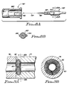
- the garter or canted coil springs 90 and 96 comprise helically wound spring elements configured in a circle, thus forming doughnut-shaped elements. As indicated above, these springs advantageously provide multiple electrical contacts around the entire periphery of the elements with which they come in contact, as shown best in Figs. 9A and 9B. Such garter springs are commercially available from, for example, Bal-Seal Corporation, of Santa Ana, California.
- a lead lock button 70 provides a mechanism for locking the connecting end 62 of the lead 64 into its desired position within the receiving channel 72 of the feedthrough connector.
- the lead lock button 70 is a relative short annular element having an opening 71 through the center thereof. This opening has a diameter sufficiently large to allow the connecting end 62 of the pacemaker lead 64 to be snugly passed therethrough.
- the button 70 further has a circumferential lip 102 at one end thereof (used to facilitate gripping the button as it is slid between its open and locked positions in the receiving channel 72) and a plurality of small detent bumps 104 near the other end, used to hold the button in either of its two positions.
- a short section of tubular or annular resilient material 103 such as silicon rubber, is held captive within the receiving channel 72 when the lead lock button is inserted.
- This annular resilient material 103 functions much like a collar having an adjustable inner diameter. When the lead lock button is in one position, the diameter of the collar allows the electrical lead to pass therethrough. When the lead lock button is in its other position, explained below, the collar assumes a much smaller diameter that pinches the lead, thereby preventing the lead from any axial movement.
- the resilient material 103 has a circumferential groove 105 on the outside diameter thereof to allow it to bulge or bend inwardly upon axial compression, as explained below.
- the material from which the button is made, in conjunction with the thickness of the walls of the button 70, and the plurality of detent bumps 104 (which engage circumferential grooves around the inside of the third conductive section 88) allow the button to snap into an open or locked position in much the same manner as the cap of a felt-tip pen (which includes one or more circumferential grooves) snaps on to the pen body (which includes a plurality of detent bumps).
- a captive open position (Fig. 6B) that allows the lead 62 to freely pass into or out of the receiving channel 72; and (2) a closed position (Fig. 6A) wherein the lead 62 is locked into the receiving channel.
- a captive open position (Fig. 6B) that allows the lead 62 to freely pass into or out of the receiving channel 72
- a closed position (Fig. 6A) wherein the lead 62 is locked into the receiving channel.
- the detent bumps 104 engage grooves 108 and 109, thus holding the locking button captive within the connectors and the resilient material 103 is held captive between the end of the nonconductive sections 91, 93 and the end of the lead lock button 70.
- the material 103 is not substantially axially compressed, and the lead 62 can pass therethrough.
- the detent bumps 104 engage grooves 109 and 110, and the resilient material 103 is subjected to a significant axial compression, which compression causes it to fold or bend at the groove 105 and bulge radially inward into the receiving channel 72.
- This action causes the resilient material 103 to firmly grip and compress the lead 62 around its circumference, much like a shrinking collar.
- this gripping action further provides an active (under pressure) seal that totally and completely blocks the entry of any body fluids into the receiving channel 72.
- the resilient tubular material 103 is a noncompressible elastomer, such as silicone or urethane.
- the gripping action on the lead locking button 70 places the elastomer of the lead lock mechanism in firm contact with the silicon rubber of the pacing lead. As has been indicated, this action not only provides a very effective (tight) and active (under pressure) seal, but it also provides a very firm grip or lock because of the high coefficient of friction of these materials.
- the lead locking button 70 is preferably made from a nonconductive biocompatible thermoplastic resin, such as polysurfone or nylon.
- sealing ridges 67 placed around the circumference of the connecting end 62 of the lead 64 in accordance with the VS-1A standard (or other standards) are tightly received within the opening 71 of the lead lock button 70 and/or the receiving channel 72. These ridges provide a secondary or back-up passive seal that further prevents any body fluids from entering the channel 72, just as do the silicone seal ridges 89 previously described.
- the case 61 of the pacemaker 60 is typically assembled in halves, commonly known as clamshells, with the two halves being welded together around their periphery once all of the electrical components have been placed therein.
- the welding seam for a prior art pacemaker, for example, is shown as 113 in Fig. 1
- such assembly techniques can continue to be used. That is, once the barrel assembly 74 has been assembled, it is positioned within a suitable opening within that half of the pacemaker 60 containing the other electrical components (circuits 12 and battery 14).
- the other half of the pacemaker case is welded or otherwise hermetically bonded to the half of the pacemaker case containing all of the pacemaker elements, and the open end 72 of the barrel assembly 74 is welded or otherwise bonded to both pacemaker case halves, in order to hermetically seal the entire pacemaker case.
- the hermeticity of the barrel assembly provides a measured leak rate of no greater than 2 x 10E-9 atm-cc/sec of air, when tested in accordance with MIL-STD-883, method 1014, condition A.
- the hermeticity of the pacer assembly may be somewhat less than this (i.e., a slightly higher measured rate of leakage) due to the aging of the barrel assembly, which aging may degrade the hermeticity level somewhat.
- a hermeticity level for the pacer assembly of 2 x 10 ⁇ 9 Nm/s (2 x 10E-8 atm-cc/sec) would be acceptable.
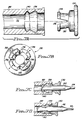
- FIGs. 7A-7D an alternative embodiment of the lead locking means of the present invention is illustrated.
- this embodiment utilizes a collet 130 that is adapted to be slidably inserted into the receiving channel 72' of the feedthrough connector.
- the collet 130 includes a circumferential lip 132 (used to help push the collet into and pull the collet out of the receiving channel 72') and an engaging detent rib 134.
- Four slits 136 uniformly spaced around the periphery of the body of the collet, allow the detent rib 134 to be radially compressed.
- the material from which the collet is made e.g.
- an engineering biocompatible thermoplastic resin such as polysurfone or nylon
- receives grooves 138 and 140 in the third section 88' of the barrel assembly are designed to receive the rib 134 as the collet 130 is pushed into the receiving channel.
- the diameter of the first groove 138 is larger than the diameter of the second groove 140.
- FIG. 7C This open position is illustrated in Fig. 7C.
- the collet 130 is held captive within the connector in this open position, thereby preventing the collet from becoming misplaced.
- the collet 130 is further slid into the receiving channel 72', such that the detent rib 134 engages the second groove 140, the collet is compressed to the point where it squeezes the body of the connecting end 62 of the lead 64 and firmly locks the lead into its inserted position.
- the detent rib 134 residing in the second groove 140
- the collet is in its "locked” position and the lead can not be removed from the connector.
- This locked position is shown in Fig. 7D.
- the lead is released by using a suitable tool to engage the circumferential lip or rim 132 so that the collet can be pulled or slid from its "locked” position to its "open” position.
- a barrel assembly 74'' includes a plurality of keyed channels 142 along the inside of a third section 88'' of the barrel assembly. These keyed channels run longitudinally for a short distance and then make a right angle and run circumferentially. Protruding pins 144, or equivalent engaging elements, are placed into the proximal end 62' of the pacing lead. These pins 144 are received within the keyed channels 142 when the lead is inserted into the receiving channel 72'' of the connector.
- the lead is rotated relative to the receiving channel 72'', thereby placing the pins 144 at the extreme end of the keyed channels 144. With the pins in this position, the lead cannot be longitudinally removed from the receiving channel 72''. Hence, the lead is locked into the connector. Removal of the lead is accomplished by twisting the lead relative to the connector in the other direction until the pins are aligned with the longitudinal portion of the channel 142, at which time the lead can be pulled back out of the connector.
- This type of lead locking mechanism is commonly known as a bayonet-type engagement. Typically, less than 1/8 of a turn is required to lock or unlock the lead. This is felt to provide a significant improvement over prior art devices where the lead must be threadably inserted into a recess within the pacemaker, typically involving many turns, and always involving relative rotation between the case and lead in excess of 360 degrees.
- Fig. 5 illustrates an alternative manner in which the barrel assembly 74, of the type previously described in connection with Figs. 4 and 6A, could be used with a circular pacemaker case 120.
- the location of the pacemaker circuits within the housing is altered slightly in order to better utilize the available space within the device.
- Fig. 5 depicts the pacemaker electrical circuits as being divided into two portions: the pulse generator circuits 122 and the telemetry circuits 124.
- Those skilled in the pacemaker art could readily divide the pacemaker circuits into these, or other, groups for the purpose of optimally utilizing the available space within the pacemaker, thereby allowing the pacemaker to be as small as possible.
Abstract
Claims (11)
- Dispositif médical implantable comprenant:
un boîtier (61) scellé hermétiquement;
un circuit électrique (12) à l'intérieur du boîtier;
un connecteur dans le boîtier, comprenant:
une structure (74) de barillet tubulaire ayant une extrémité ouverte (78) et une extrémité fermée (76), et un axe de barillet passant par l'extrémité ouverte (78) et l'extrémité fermée (76), l'extrémité ouverte (78) étant fixée à une surface exposée du boîtier (61), l'extrémité fermée (76) étant intérieure au boîtier (61), la structure (74) de barillet tubulaire créant un canal tubulaire (72) qui fait saillie à l'intérieur du boîtier scellé (61), mais ne rompt pas l'étanchéité du boîtier (61), l'intérieur du canal tubulaire (72) s'ouvrant vers l'extérieur du boîtier scellé (61) à travers l'extrémité ouverte (78),
un moyen pour établir un contact électrique entre le canal tubulaire (72) et le circuit électrique (12), et
un moyen de verrouillage (70) pour verrouiller de façon amovible et serrer un conducteur électrique (64) inséré axialement dans l'extrémité ouverte (78) du canal tubulaire (72),
le moyen de verrouillage pouvant être actionné avec une rotation relative inférieure à 360° entre le conducteur et la structure de barillet tubulaire, caractérisé en ce que:
le canal tubulaire (72) comprend en outre une pluralité de parties (80, 84) cylindriques conductrices coaxiales à l'axe du barillet, la dimension du diamètre de parties (80, 84) cylindriques successives décroissant progressivement de l'extrémité ouverte (78) jusqu'à l'extrémité fermée (76);
le contact électrique étant établi entre des parties sélectionnées parmi les parties cylindriques (80, 84) et le circuit électrique (12); et le conducteur électrique (64) étant en contact électrique avec les parties cylindriques (80, 84) du canal tubulaire (72) qui sont sélectionnées (fig. 4, 6);
dans lequel des parties successives de la pluralité de parties cylindriques (80, 84) conductrices sont séparées par une partie cylindrique (82, 86) non conductrice isolante;
et dans lequel des parties cylindriques (80, 84) conductrices successives de la structure de barillet (74) sont à distance les unes des autres et se chevauchent à leurs extrémités adjacentes respectives, en définissant ainsi entre elles une région de chevauchement, les parties (82, 86) cylindriques non conductrices isolantes étant disposées dans toute la région de chevauchement entre des parties cylindriques (80, 84) conductrices successives, les extrémités des parties cylindriques (80, 84) conductrices étant ainsi maintenues à distance les unes des autres sans se toucher et électriquement isolées les unes des autres par les parties cylindriques (82, 86) non conductrices isolantes. - Dispositif médical implantable selon la revendication 1, dans lequel le boîtier (61) scellé hermétiquement ne doit pas présenter un taux de fuite supérieur à 2 x 10⁻⁹ Nm/s (2 x 10E-8 atm-c³/s).
- Dispositif médical implantable selon la revendication 1, dans lequel le boîtier (61) scellé hermétiquement comprend un stimulateur cardiaque (60), et le conducteur électrique (64) comprend un conducteur (64) pour stimulateur cardiaque adapté à connecter le stimulateur cardiaque (60) à un emplacement souhaité d'un tissu.
- Dispositif médical implantable selon la revendication 1, dans lequel le moyen de verrouillage (70) peut être actionné sensiblement sans aucune rotation relative entre le conducteur électrique (64) et la structure (74) de barillet tubulaire.
- Dispositif médical implantable selon la revendication 1, dans lequel le moyen pour établir un contact électrique comprend:
un ressort à enroulement incliné (90, 96) positionné sur l'intérieur des parties cylindriques (80, 84) sélectionnées de façon à établir un contact électrique avec celles-ci en une multiplicité d'emplacements; et
un moyen (94, 100) à fil métallique pour établir un contact électrique avec l'extérieur des parties cylindriques (80, 84) sélectionnées et le circuit électrique (12). - Dispositif médical implantable selon l'une quelconque des revendications précédentes, dans lequel
le moyen de verrouillage comprend:
des premier (109, 110) et second (108, 109)
moyens d'engagement à distance les uns des autres sur l'intérieur du canal tubulaire;
une bague de verrouillage (70) ayant une pluralité de bosses de positionnement (104), la bague de verrouillage (70) ayant un diamètre intérieur permettant au conducteur électrique (64) d'être ajusté à travers celle-ci et un diamètre extérieur qui permet à la bague (70) d'être insérée de façon coulissante dans l'extrémité ouverte (78) du canal tubulaire (72), au moins une bosse de positionnement (104) de la bague de verrouillage (70) étant reçue par les premiers (109, 110) ou deuxième (108, 109) moyens d'engagement selon la profondeur à laquelle la bague de verrouillage (70) est insérée dans le canal tubulaire (72);
un moyen de serrage destiné à serrer le conducteur électrique chaque fois qu'au moins une bosse de positionnement (104) est reçue par le premier moyen d'engagement (109, 110), et destiné à libérer le conducteur électrique chaque fois qu'au moins une bosse de positionnement (104) est reçue par le second moyen d'engagement (108, 109). - Dispositif médical implantable selon la revendication 6, dans lequel les premier (109, 110) et second (108, 109) moyens d'engagement comprennent des première (109, 110) et seconde (108, 109) gorges circonférentielles sur l'intérieur du canal tubulaire (72) à proximité de son extrémité ouverte (78); et dans lequel au moins l'une des bosses de positionnement (104) de la bague de verrouillage (704) s'encliquette dans l'une ou l'autre des première (109, 110) et seconde (108, 109) gorges selon la profondeur à laquelle la bague de verrouillage (70) est repoussée à l'intérieur du canal tubulaire (72).
- Dispositif médical implantable selon la revendication 7, dans lequel le canal tubulaire (72) de la structure de barillet (74) comporte en outre un moyen de butée positionné à proximité desdites première (109, 110) et seconde (108, 109) gorges circonférentielles, et dans lequel ledit moyen de serrage est maintenu captif entre le moyen de butée et la bague de verrouillage (70), le moyen de serrage comprenant une section annulaire (103) en matériau élastique, ayant un diamètre intérieur qui permet au conducteur électrique (64) de passer dans celui-ci lorsque le matériau élastique n'est pas soumis à une compression axiale, et dans lequel le matériau élastique est en outre soumis à une compression axiale lorsque ladite au moins une bosse de positionnement (104) est reçue à l'intérieur de la première gorge (109, 110), cette compression axiale provoquant un renflement du matériau élastique vers l'intérieur du canal tubulaire (72), ce qui réduit suffisamment le diamètre intérieur de la section élastique annulaire (103) pour serrer fermement le conducteur électrique (64) afin d'empêcher son mouvement axial.
- Dispositif médical implantable selon la revendication 7, dans lequel le diamètre de la première gorge (138) est supérieur au diamètre de la seconde gorge (140), et dans lequel la bague de verrouillage comprend un collet (130) compressible radialement, ce collet ayant un premier diamètre intérieur qui permet au conducteur électrique (64) de passer en coulissant dans celui-ci lorsque l'épaulement du collet (130) est reçu à l'intérieur de la première gorge (138), et dans lequel le collet (130) présente un second diamètre intérieur qui serre de façon verrouillable le conducteur électrique (64) lorsque l'épaulement du collet est reçu à l'intérieur de la seconde gorge (140) (fig. 7).
- Dispositif médical implantable selon la revendication 1, dans lequel le moyen de verrouillage comprend des moyens d'engagement sur l'intérieur du canal tubulaire (72'') qui s'emboîtent dans des moyens d'engagement adaptés (144) sur le conducteur électrique (62') chaque fois qu'une extrémité proximale du conducteur électrique (62') est insérée dans l'extrémité ouverte du canal tubulaire (72'') (fig. 8).
- Dispositif médical implantable selon la revendication 10, dans lequel les moyens d'engagement du canal tubulaire (72'') et du conducteur électrique (62') entrent en contact de façon verrouillable de manière à empêcher que le conducteur électrique (62') sorte du canal tubulaire (72'') chaque fois que le conducteur électrique (62') est mis en rotation d'une fraction de tour par rapport au canal tubulaire (72'') (fig. 8).
Applications Claiming Priority (3)
| Application Number | Priority Date | Filing Date | Title |
|---|---|---|---|
| US24089588A | 1988-09-01 | 1988-09-01 | |
| US240895 | 1988-09-01 | ||
| PCT/US1989/003809 WO1990002581A1 (fr) | 1988-09-01 | 1989-09-01 | Raccord de passage d'alimentation pour dispositif medical implantable |
Publications (2)
| Publication Number | Publication Date |
|---|---|
| EP0404877A1 EP0404877A1 (fr) | 1991-01-02 |
| EP0404877B1 true EP0404877B1 (fr) | 1995-03-15 |
Family
ID=22908368
Family Applications (1)
| Application Number | Title | Priority Date | Filing Date |
|---|---|---|---|
| EP89910721A Expired - Lifetime EP0404877B1 (fr) | 1988-09-01 | 1989-09-01 | Raccord de passage d'alimentation pour dispositif medical implantable |
Country Status (5)
| Country | Link |
|---|---|
| EP (1) | EP0404877B1 (fr) |
| JP (1) | JPH03502656A (fr) |
| AU (1) | AU611328B2 (fr) |
| DE (1) | DE68921744T2 (fr) |
| WO (1) | WO1990002581A1 (fr) |
Cited By (1)
| Publication number | Priority date | Publication date | Assignee | Title |
|---|---|---|---|---|
| US7210968B1 (en) | 2005-01-04 | 2007-05-01 | Pacesetter, Inc. | Dual-locking mechanism for lead and header attachment in pre-molded headers |
Families Citing this family (13)
| Publication number | Priority date | Publication date | Assignee | Title |
|---|---|---|---|---|
| JPH0745221Y2 (ja) * | 1990-03-16 | 1995-10-18 | 日本ゼオン株式会社 | ペーシング装置 |
| DE19622669A1 (de) * | 1996-06-05 | 1997-12-11 | Implex Gmbh | Implantierbare Einheit |
| US7083474B1 (en) | 2004-12-08 | 2006-08-01 | Pacesetter, Inc. | System for lead retention and sealing of an implantable medical device |
| DE102005020071A1 (de) * | 2005-04-22 | 2006-10-26 | Biotronik Crm Patent Ag | Herzschrittmacher |
| US7711428B2 (en) | 2007-01-18 | 2010-05-04 | Medtronic, Inc. | Hermetic lead connector assembly |
| US8131370B2 (en) | 2007-01-18 | 2012-03-06 | Medtronic, Inc | Methods of manufacturing a hermetic lead connector |
| US7720538B2 (en) | 2007-01-18 | 2010-05-18 | Medtronic, Inc. | Internal hermetic lead connector for implantable device |
| US7711427B2 (en) * | 2007-01-18 | 2010-05-04 | Medtronis, Inc. | Internal hermetic lead connector for implantable device |
| US9399127B2 (en) | 2007-12-21 | 2016-07-26 | Boston Scientific Neuromodulation Corporation | Neurostimulation lead with stiffened proximal array |
| US8391982B2 (en) | 2008-01-31 | 2013-03-05 | Boston Scientific Neuromodulation Corporation | Lead with lead stiffener for implantable electrical stimulation systems and methods of making and using |
| WO2010034343A1 (fr) | 2008-09-24 | 2010-04-01 | Neurotech | Ensemble connecteur électrique hyperboloïde |
| US10608354B2 (en) * | 2017-03-23 | 2020-03-31 | Verily Life Sciences Llc | Implantable connector with two electrical components |
| EP3635819A1 (fr) * | 2017-06-08 | 2020-04-15 | Stäubli Electrical Connectors AG | Élément de connexion électrique |
Family Cites Families (4)
| Publication number | Priority date | Publication date | Assignee | Title |
|---|---|---|---|---|
| GB623798A (en) * | 1947-05-15 | 1949-05-23 | Pirelli General Cable Works | Improvements in or relating to tension joints and clamps for steel-cored electric conductors |
| GB1598793A (en) * | 1977-03-10 | 1981-09-23 | Needle Industries Ltd | Cardiac pacemakers |
| JPS5793343U (fr) * | 1980-11-26 | 1982-06-08 | ||
| DE3622116A1 (de) * | 1986-07-02 | 1988-01-14 | Rose Walter Gmbh & Co Kg | Vorrichtung zum kontaktieren eines elektrischen leiters mit kontaktfederteilen |
-
1989
- 1989-09-01 EP EP89910721A patent/EP0404877B1/fr not_active Expired - Lifetime
- 1989-09-01 AU AU43080/89A patent/AU611328B2/en not_active Ceased
- 1989-09-01 DE DE68921744T patent/DE68921744T2/de not_active Expired - Fee Related
- 1989-09-01 JP JP51009789A patent/JPH03502656A/ja active Pending
- 1989-09-01 WO PCT/US1989/003809 patent/WO1990002581A1/fr active IP Right Grant
Cited By (1)
| Publication number | Priority date | Publication date | Assignee | Title |
|---|---|---|---|---|
| US7210968B1 (en) | 2005-01-04 | 2007-05-01 | Pacesetter, Inc. | Dual-locking mechanism for lead and header attachment in pre-molded headers |
Also Published As
| Publication number | Publication date |
|---|---|
| DE68921744D1 (de) | 1995-04-20 |
| DE68921744T2 (de) | 1995-11-23 |
| AU4308089A (en) | 1990-04-02 |
| EP0404877A1 (fr) | 1991-01-02 |
| JPH03502656A (ja) | 1991-06-20 |
| AU611328B2 (en) | 1991-06-06 |
| WO1990002581A1 (fr) | 1990-03-22 |
Similar Documents
| Publication | Publication Date | Title |
|---|---|---|
| EP0448651B1 (fr) | Connecteur de traversee pour appareil medical implantable | |
| US6643550B2 (en) | Multi-polar connector | |
| EP2134406B1 (fr) | Ensemble connecteur enfichable en ligne pour utilisation avec des dispositifs médicaux | |
| EP0404877B1 (fr) | Raccord de passage d'alimentation pour dispositif medical implantable | |
| AU661642B2 (en) | Coaxial bipolar connector assembly for implantable medical device | |
| EP2244337B1 (fr) | Pile de connecteur en ligne avec capacité de test | |
| US20080255631A1 (en) | Integrated header connector system | |
| US20030163171A1 (en) | In-line lead header for an implantable medical device | |
| US20220249842A1 (en) | Biostimulator feedthrough having integrated electrode cup | |
| US7035689B1 (en) | Connector and retention mechanism for an implantable medical device | |
| US8700160B2 (en) | Hyperboloid electrical connector assembly | |
| US5795165A (en) | Electrode connector jack for an implantable medical electrical stimulator | |
| GB2127629A (en) | Implantable medical device with sealed electrical coupling | |
| US20200298010A1 (en) | Implantable medical device with locking datum arrangement between df4/is4 assembly and header | |
| EP2362801A1 (fr) | Ensemble connecteur électrique hyperboloïde |
Legal Events
| Date | Code | Title | Description |
|---|---|---|---|
| PUAI | Public reference made under article 153(3) epc to a published international application that has entered the european phase |
Free format text: ORIGINAL CODE: 0009012 |
|
| 17P | Request for examination filed |
Effective date: 19900427 |
|
| AK | Designated contracting states |
Kind code of ref document: A1 Designated state(s): DE FR GB IT NL SE |
|
| 17Q | First examination report despatched |
Effective date: 19930129 |
|
| RAP1 | Party data changed (applicant data changed or rights of an application transferred) |
Owner name: PACESETTER AB |
|
| GRAA | (expected) grant |
Free format text: ORIGINAL CODE: 0009210 |
|
| AK | Designated contracting states |
Kind code of ref document: B1 Designated state(s): DE FR GB IT NL SE |
|
| REF | Corresponds to: |
Ref document number: 68921744 Country of ref document: DE Date of ref document: 19950420 |
|
| ITF | It: translation for a ep patent filed |
Owner name: BARZANO' E ZANARDO ROMA S.P.A. |
|
| ET | Fr: translation filed | ||
| PGFP | Annual fee paid to national office [announced via postgrant information from national office to epo] |
Ref country code: SE Payment date: 19950918 Year of fee payment: 7 |
|
| PLBE | No opposition filed within time limit |
Free format text: ORIGINAL CODE: 0009261 |
|
| STAA | Information on the status of an ep patent application or granted ep patent |
Free format text: STATUS: NO OPPOSITION FILED WITHIN TIME LIMIT |
|
| 26N | No opposition filed | ||
| REG | Reference to a national code |
Ref country code: GB Ref legal event code: 732E |
|
| NLS | Nl: assignments of ep-patents |
Owner name: PACESETTER, INC. |
|
| REG | Reference to a national code |
Ref country code: FR Ref legal event code: TP |
|
| PG25 | Lapsed in a contracting state [announced via postgrant information from national office to epo] |
Ref country code: SE Effective date: 19960902 |
|
| EUG | Se: european patent has lapsed |
Ref document number: 89910721.3 |
|
| PGFP | Annual fee paid to national office [announced via postgrant information from national office to epo] |
Ref country code: GB Payment date: 19970826 Year of fee payment: 9 |
|
| PGFP | Annual fee paid to national office [announced via postgrant information from national office to epo] |
Ref country code: FR Payment date: 19980820 Year of fee payment: 10 |
|
| PGFP | Annual fee paid to national office [announced via postgrant information from national office to epo] |
Ref country code: NL Payment date: 19980825 Year of fee payment: 10 |
|
| PGFP | Annual fee paid to national office [announced via postgrant information from national office to epo] |
Ref country code: DE Payment date: 19980826 Year of fee payment: 10 |
|
| PG25 | Lapsed in a contracting state [announced via postgrant information from national office to epo] |
Ref country code: GB Free format text: LAPSE BECAUSE OF NON-PAYMENT OF DUE FEES Effective date: 19980901 |
|
| GBPC | Gb: european patent ceased through non-payment of renewal fee |
Effective date: 19980901 |
|
| PG25 | Lapsed in a contracting state [announced via postgrant information from national office to epo] |
Ref country code: NL Free format text: LAPSE BECAUSE OF NON-PAYMENT OF DUE FEES Effective date: 20000401 |
|
| PG25 | Lapsed in a contracting state [announced via postgrant information from national office to epo] |
Ref country code: FR Free format text: LAPSE BECAUSE OF NON-PAYMENT OF DUE FEES Effective date: 20000531 |
|
| NLV4 | Nl: lapsed or anulled due to non-payment of the annual fee |
Effective date: 20000401 |
|
| PG25 | Lapsed in a contracting state [announced via postgrant information from national office to epo] |
Ref country code: DE Free format text: LAPSE BECAUSE OF NON-PAYMENT OF DUE FEES Effective date: 20000701 |
|
| REG | Reference to a national code |
Ref country code: FR Ref legal event code: ST |
|
| PG25 | Lapsed in a contracting state [announced via postgrant information from national office to epo] |
Ref country code: IT Free format text: LAPSE BECAUSE OF NON-PAYMENT OF DUE FEES;WARNING: LAPSES OF ITALIAN PATENTS WITH EFFECTIVE DATE BEFORE 2007 MAY HAVE OCCURRED AT ANY TIME BEFORE 2007. THE CORRECT EFFECTIVE DATE MAY BE DIFFERENT FROM THE ONE RECORDED. Effective date: 20050901 |