EP2244337B1 - Pile de connecteur en ligne avec capacité de test - Google Patents
Pile de connecteur en ligne avec capacité de test Download PDFInfo
- Publication number
- EP2244337B1 EP2244337B1 EP10004189.6A EP10004189A EP2244337B1 EP 2244337 B1 EP2244337 B1 EP 2244337B1 EP 10004189 A EP10004189 A EP 10004189A EP 2244337 B1 EP2244337 B1 EP 2244337B1
- Authority
- EP
- European Patent Office
- Prior art keywords
- header
- stack
- bore
- encapsulated
- encapsulation layer
- Prior art date
- Legal status (The legal status is an assumption and is not a legal conclusion. Google has not performed a legal analysis and makes no representation as to the accuracy of the status listed.)
- Active
Links
Images


Classifications
-
- H—ELECTRICITY
- H01—ELECTRIC ELEMENTS
- H01R—ELECTRICALLY-CONDUCTIVE CONNECTIONS; STRUCTURAL ASSOCIATIONS OF A PLURALITY OF MUTUALLY-INSULATED ELECTRICAL CONNECTING ELEMENTS; COUPLING DEVICES; CURRENT COLLECTORS
- H01R24/00—Two-part coupling devices, or either of their cooperating parts, characterised by their overall structure
- H01R24/58—Contacts spaced along longitudinal axis of engagement
-
- A—HUMAN NECESSITIES
- A61—MEDICAL OR VETERINARY SCIENCE; HYGIENE
- A61N—ELECTROTHERAPY; MAGNETOTHERAPY; RADIATION THERAPY; ULTRASOUND THERAPY
- A61N1/00—Electrotherapy; Circuits therefor
- A61N1/18—Applying electric currents by contact electrodes
- A61N1/32—Applying electric currents by contact electrodes alternating or intermittent currents
- A61N1/36—Applying electric currents by contact electrodes alternating or intermittent currents for stimulation
- A61N1/372—Arrangements in connection with the implantation of stimulators
- A61N1/375—Constructional arrangements, e.g. casings
- A61N1/3752—Details of casing-lead connections
-
- H—ELECTRICITY
- H01—ELECTRIC ELEMENTS
- H01R—ELECTRICALLY-CONDUCTIVE CONNECTIONS; STRUCTURAL ASSOCIATIONS OF A PLURALITY OF MUTUALLY-INSULATED ELECTRICAL CONNECTING ELEMENTS; COUPLING DEVICES; CURRENT COLLECTORS
- H01R13/00—Details of coupling devices of the kinds covered by groups H01R12/70 or H01R24/00 - H01R33/00
- H01R13/02—Contact members
- H01R13/22—Contacts for co-operating by abutting
- H01R13/24—Contacts for co-operating by abutting resilient; resiliently-mounted
- H01R13/2407—Contacts for co-operating by abutting resilient; resiliently-mounted characterized by the resilient means
- H01R13/2421—Contacts for co-operating by abutting resilient; resiliently-mounted characterized by the resilient means using coil springs
-
- H—ELECTRICITY
- H01—ELECTRIC ELEMENTS
- H01R—ELECTRICALLY-CONDUCTIVE CONNECTIONS; STRUCTURAL ASSOCIATIONS OF A PLURALITY OF MUTUALLY-INSULATED ELECTRICAL CONNECTING ELEMENTS; COUPLING DEVICES; CURRENT COLLECTORS
- H01R13/00—Details of coupling devices of the kinds covered by groups H01R12/70 or H01R24/00 - H01R33/00
- H01R13/58—Means for relieving strain on wire connection, e.g. cord grip, for avoiding loosening of connections between wires and terminals within a coupling device terminating a cable
- H01R13/59—Threaded ferrule or bolt operating in a direction parallel to the cable or wire
-
- H—ELECTRICITY
- H01—ELECTRIC ELEMENTS
- H01R—ELECTRICALLY-CONDUCTIVE CONNECTIONS; STRUCTURAL ASSOCIATIONS OF A PLURALITY OF MUTUALLY-INSULATED ELECTRICAL CONNECTING ELEMENTS; COUPLING DEVICES; CURRENT COLLECTORS
- H01R2107/00—Four or more poles
-
- H—ELECTRICITY
- H01—ELECTRIC ELEMENTS
- H01R—ELECTRICALLY-CONDUCTIVE CONNECTIONS; STRUCTURAL ASSOCIATIONS OF A PLURALITY OF MUTUALLY-INSULATED ELECTRICAL CONNECTING ELEMENTS; COUPLING DEVICES; CURRENT COLLECTORS
- H01R2201/00—Connectors or connections adapted for particular applications
- H01R2201/12—Connectors or connections adapted for particular applications for medicine and surgery
-
- Y—GENERAL TAGGING OF NEW TECHNOLOGICAL DEVELOPMENTS; GENERAL TAGGING OF CROSS-SECTIONAL TECHNOLOGIES SPANNING OVER SEVERAL SECTIONS OF THE IPC; TECHNICAL SUBJECTS COVERED BY FORMER USPC CROSS-REFERENCE ART COLLECTIONS [XRACs] AND DIGESTS
- Y10—TECHNICAL SUBJECTS COVERED BY FORMER USPC
- Y10T—TECHNICAL SUBJECTS COVERED BY FORMER US CLASSIFICATION
- Y10T29/00—Metal working
- Y10T29/49—Method of mechanical manufacture
- Y10T29/49002—Electrical device making
- Y10T29/49004—Electrical device making including measuring or testing of device or component part
-
- Y—GENERAL TAGGING OF NEW TECHNOLOGICAL DEVELOPMENTS; GENERAL TAGGING OF CROSS-SECTIONAL TECHNOLOGIES SPANNING OVER SEVERAL SECTIONS OF THE IPC; TECHNICAL SUBJECTS COVERED BY FORMER USPC CROSS-REFERENCE ART COLLECTIONS [XRACs] AND DIGESTS
- Y10—TECHNICAL SUBJECTS COVERED BY FORMER USPC
- Y10T—TECHNICAL SUBJECTS COVERED BY FORMER US CLASSIFICATION
- Y10T29/00—Metal working
- Y10T29/49—Method of mechanical manufacture
- Y10T29/49002—Electrical device making
- Y10T29/49117—Conductor or circuit manufacturing
- Y10T29/49169—Assembling electrical component directly to terminal or elongated conductor
- Y10T29/49171—Assembling electrical component directly to terminal or elongated conductor with encapsulating
- Y10T29/49172—Assembling electrical component directly to terminal or elongated conductor with encapsulating by molding of insulating material
Definitions
- the invention relates to a method for manufacturing an in-line connector according to the preamble of claim 1 and to a connector header assembly according to the preamble of claim 11.
- US 2009/048638 A1 discloses a connector assembly for use with implantable medical devices which connector assembly is generally formed by coupling a plurality of contact housings, sealing rings and leaf spring contact elements to form a connector having a common bore for receiving a medical lead cable Contact grooves for positioning the leaf spring contact elements are formed in part by assembling multiple components together
- US 2007/202728 A1 discloses a medical device connector assembly wherein the connector assembly includes a core element, a plurality of conductive members positioned along the core element and a plurality of sealing members positioned between the conductive members wherein the sealing members having an outer surface supported by the core element A single end cap which frictionally slides into engagement with the core element and a set screw block on the opposite end is provided.
- Implantable medical devices for providing electrical stimulation to body tissues, for monitoring physiologic conditions, and for providing alternative treatments to drugs are well known in the art.
- exemplary implantable medical devices include implantable cardio defibrillators, pacemakers, and programmable neurostimulator pulse generators, which are collectively herein referred to as "implantable medical devices" or IMDs.
- IMDs typically incorporate a hermetically sealed device enclosing a power source and electronic circuitry.
- the header assembly includes electrical contact elements that are electrically coupled to the electronic circuits or to the power source located inside the can via conductive terminals.
- the header assembly provides a means for electrically communicating, via an external medical lead cable, the electronic circuits or power source located inside the device with the actual stimulation point
- in-line connectors While discussed with specific implantable applications, may be used in other industries and applications, including consumer electronics, electrical connectors, and industrial electronics, such as aviation, automotive, oil and gas, etc.
- the invention comprises the features in the characterising part of claims 1 and 11.
- in-line connector stacks are disclosed Examples include in-line connector stacks placed inside an encapsulation layer so that the encapsulated stack may be tested for aligning and conductivity before it is installed or placed into a header of an IMD.
- Different in-line connector stacks comprising different seal and conductive elements may be used with the encapsulation layer concept of the present application.
- the specification describes specific applications of the connector stacks in combination with a header of an IMD, the stacks may be used in other applications and industries requiring multiple conductive sources in an in-line configuration.
- An exemplary method is directed to a method for manufacturing an in-line connector.
- the method comprising encapsulating an in-line connector stack comprising a common bore with an encapsulation layer to form an encapsulated stack comprising two end surfaces; wherein a plurality of seal elements and conductive contact elements are located between the two end surfaces; aligning a plurality of slots formed on the encapsulation layer with the plurality of conductive contact elements; placing two end caps at the two end surfaces of the encapsulation layer to retain the plurality of seal elements and conductive contact elements inside the encapsulation layer; and wherein the encapsulated stack comprises a common bore and two end openings.
- An exemplary apparatus comprises a header assembly comprising a header comprising a bore, an in-line connector stack comprising a plurality alternating seal elements and conductive contact elements encapsulated by an encapsulation layer positioned inside the bore, and a snap fit end cap comprising a bore mechanically engaged to the header, which defines a seam therebetween, and wherein the header comprises a plurality of slots aligned with a plurality of slots formed on the encapsulation layer
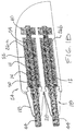
- FIG. 1A to FIG. 7A show a stackable connector in various stages of assembly and different views for clarity.
- the connector stack 10 which comprises a plurality of seal elements 50, conductive elements 52, and spring contact elements 54, is configured to fit inside an encapsulation layer 12 to form an encapsulated stack 14.
- the encapsulated stack 14 is configured to fit inside a molded header 16, which has slots 56 or openings for accessing to weld the leads 58 from the electronic case (See, e.g., FIG. 7A and 5B ) with the conductive elements 54.
- the openings 56 are then back filled with a curable implantable material, such as silicone and other medical grade elastomers or resins.
- Another opening 56.1 may be provided for inserting a holding ring 60 with a locking screw 60.1 for more permanently securing the lead cable 44 to the connector stack, as shown in FIG. 6A .
- end caps 15 are incorporated, either at only one end of the stack 10 or at both ends, as shown in FIG. 1A in exploded view.
- the end caps 15 are positioned adjacent an end seal element 50.1 and provide engagement with the encapsulation layer 12.
- the end caps 15 provide added sealing by incorporating interior ribs or rings for sealing against the electrical lead cable 44.
- the end caps 15 may have the same or higher durometer as the seal element but may be lower to facilitate insertion at the inlet.
- the end seal element 50.1 may be similar to the middle seal elements but also includes sealing means, such as ribs and projections, for sealing against the end cap.
- the encapsulation layer 12 comprises a generally cylindrical tube comprising one or more slots 64.
- the number of slots 64 corresponds to the number of conductive contact elements 52, which can vary depending on the desired applications and electrical contacts.
- the encapsulation layer 12 comprises a lip 74 at each end for engaging the end cap 15.
- the in-line stack 10 comprises three conductive elements. However, less than or more than three may be incorporated without deviating from the scope of the present invention.
- the slots 64 on the insulation layer 12 align with the slots 56 on the header 16 so that leads 58 from the can 22 may be accessed and attached to the conductive elements 52.
- a feature of the present assembly and method for making an IMD, in-line stack, and header is understood to include a plurality of alternating seal elements 50 and conductive elements 52 located inside an encapsulation layer 12 comprising a plurality of slots 64, and wherein the plurality of slots align with a corresponding number of conductive elements 52.
- a canted coil spring 54 is in electrical contact with each conductive element 52. As shown in FIG. 2A , the canted coil spring 54 is located within a groove 66 formed along the inside bore 68 of the in-line stack, which is common with the bore 62 of the header 16.
- the groove 66 is formed utilizing a back wall and a side wall of a conductive contact element 52 along with a side wall of an adjacent seal element 50.
- the groove 66 may be formed using different features and walls utilizing different conductive rings and seals than as shown, such as that shown in FIG. 11 , further discussed below.
- Signals or current passing from the leads 58 ( FIG. 3A ) of an electrical housing or case are configured to pass through corresponding conductive elements 52 which then pass through corresponding springs 54 and to corresponding electrode ring terminals 70 on the lead cable 44, which then pass through corresponding electrode leads 72 ( FIG. 6A ).
- a snap fit end cap 18 is incorporated for securing the encapsulated stack 14 inside the header bore 62 of the header 16, as shown in FIGs. 3A-5A .
- the snap fit end cap 18 has provisions for engaging the header 16 and for providing an axial force on the encapsulated stack 14 to at least slightly compress the stack inside the header.
- the snap fit end cap 18 and the header 16 may incorporate interference detent arrangements that snap in place utilizing axial interference.
- a seam is defined between the end cap 18 and the header 16, which is sealed by the force or pressure of the snap fit arrangement.
- curable implantable material is applied to further seal the seam.
- one or more raised bumps or ribs 36.1 are incorporated in the bore of the end cap 18 for sealing against the exterior surface of a lead cable.
- the one or more raised bumps or ribs 36.1 would provide additional sealing from potential leakage into the bore of the in-line stack in addition the seal elements.
- the stack is aligned and can optionally be tested before placing the stack 14 into the header.
- the encapsulated stack unit 14 may be viewed a free-standing axially compressed stack that is aligned and adapted to receive an electrical lead cable 44 ( FIGs. 6A and 7A ).
- a technician can better perform quality control on the stack 14 before placing it into a header 16 or into a connector housing and then molding it in place with resin.
- a technician can only test the stack after it has been assembled onto the electrical case 22 ( FIG. 7A ), which can only be done by installing the same into a header 16.
- the in-line connector stack 14 has utility independent of being placed into the header 16 and/or for use with an implantable device.
- the encapsulation layer 12 may be made from thermoplastic or TPE material and preferably non-conductive.
- the encapsulation layer is made from a thermoset plastic and comprises a generally cylindrical shape structure comprising slots 64 and end lips 74 for retaining or engaging the end caps 15.
- a locking ring with a locking screw is incorporated in the snap fit end cap 18 ( FIG. 4B ) for securing the lead cable.
- the end cap 18 is integrally formed with the header 16 and a rear opening (not shown) is instead incorporated on the header, near element 20 of FIG. 5A .
- the stack unit 14 would be installed through the rear opening, which is subsequently back filled with a curable resin.
- the encapsulated stack 14 is over molded with a polymeric header casting resin instead of being inserted into the pre-formed header 16 as shown.
- the over molded header in this alternative embodiment, not including the pre-formed header 16, is then attached to an electronic case, i.e., sealed can, of an implantable medical device 22.
- FIGs. 1B to 3B show yet another alternative header assembly 24 comprising a double bore arrangement 26a, 26b.
- Each bore is configured to store an encapsulated stack 14, similar to the embodiment of FIGs. 1A to 7A , and has a snap fit end cap 18 for retaining the stack 14 inside the bore.
- a center rib 28 incorporates two detents in superjacent format. The two detents in superjacent format are configured for snap fit engagement with the end caps 18.
- the header 24 is configured to receive the two connector stacks 14 in a side-by-side configuration instead of one on top of another as shown in FIG. 2B .
- more than two connector stacks 14 may be incorporated into the header 24 in a side-by-side configuration, one on top of another configuration, or a pyramid type configuration.
- a set screw block 30 having a set screw 32 is incorporated in the snap fit end cap 34.
- An opening 34.3 is thus provided on a side of the frustoconical cone section of the end cap 34 to provide access to the set screw 32.
- the opening 34.3 may be back-filled with an implantable material or resin after the set screw 32 is turned to tighten against the lead cable 44 ( FIG. 5B ).
- the sect screw block 30 may be made from a plastic material and co-molded with the snap fit end cap 34.
- seal elements 36 having annular seal ribs are co-molded or over-molded with the end cap 34 for sealing against a lead cable.
- the seal elements 36 may be made from the same material as the seal elements 50, which may be an elastomer or a thermoplastic elastomer (TPE), and inserted into the end cap 34.
- TPE thermoplastic elastomer
- the end cap 34 is integrally molded with the header 24 and the header is provided with a rear opening, near element 20 ( FIG. 5B ).
- the encapsulated stack 14 may be placed into the bore of the header through the rear opening. The opening may then be back filled with an implantable material.
- a snap fit cap or flange (not shown) may also be used to close the rear opening instead of simply back filling the rear opening with a resin. The snap fit cap or flange may be use by itself to seal the rear opening or in combination with curable resin.
- FIG. 4B Also shown in the perspective transparent view FIG. 4B are three windows or slots 56 for accessing the leads 58 from the electrical case (not shown), such as a sealed can of an IMD.
- the windows are understood to be backfilled with an implantable material or resin after the leads are secured to the conductive ring contact elements.
- FIG. 4B Also shown in the perspective view of FIG. 4B is a set screw opening on the snap fit end cap 34. As such, an opening on the header for a separate holding ring with set screw may be eliminated.
- the implantable medical device 80 may be any number of devices, such as an implantable cardio defibrillator, pacemaker, and programmable neuro-stimulator pulse generator, to name a few.
- the snap fit end cap 34 is made from a plastic material and is molded with at least one groove 82 for receiving the relatively softer sealing ring 36 comprising raised bumps or ribs 36.1, such as made from silicone or a TPE material, which is separately formed and installed into the groove 82.
- the components are co-molded.
- FIG. 8 is an enlarged cross-sectional side view of an exemplary header assembly, which is similar to that shown in FIGs. 1A and 2B .
- the snap fit end cap 18 is provided with an annular lip seal 40 near the mating end and near the inlet or entrance to the bore of the end cap.
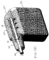
- FIG. 9 is a perspective semi-transparent view of the assembly of FIG. 4B attached to an electronic case 80.
- FIG. 10 is a cross-sectional side view of the assembly of FIG. 9 .
- FIG. 11 is a cross-sectional side view of an encapsulated stack 90 provided in accordance with alternative embodiments, which comprises an in-line stack 92 positioned inside an encapsulation layer 94. Also shown are conductive energizers 96, which separately sit in grooves 98 formed by a conductive element 100 and two adjacent seal elements 102. Note that the conductive elements 100 do not include side walls. As such, the grooves 98 are each formed by a conductive element 100 and two adjacent seal elements 102. The seal elements are each shown with a single projection or lip 104 for sealing against a lead cable. In other embodiments, two or more lips 104 may be incorporated.
- an encapsulated stack comprising an in-line stack positioned in side an encapsulation layer, which have slots or openings formed on the side thereof for aligning with respective conductive elements.
- the encapsulated stack which may be sized to fit any number of contacts as required for a particular application, is configured to facilitate assembly and testing before the encapsulated stack is completed inside a header, connector, or other in-line assembly.
- connector assembly may be used for any device that requires an in-line connection in which multiple conductive sources are to be relayed between a source generator and a source receiver, whether that device is configured for implanting or otherwise.
- thermoset and thermoplastic polymers are described for encapsulating a stack, other means may be used, such as a mechanical clamp.
Claims (16)
- Procédé de fabrication d'un connecteur en ligne (14, 16, 24, 90) comprenant :l'encapsulation d'un empilement de connecteur en ligne (10, 92) comprenant un trou d'alésage (68) avec une couche d'encapsulation (12, 94) comprenant une pluralité de fentes (64) pour former une pile encapsulée (14, 90) comprenant un trou d'alésage (62) aligné avec le trou d'alésace (68) de l'empilement de connecteur en ligne (10, 92), deux surfaces d'extrémité (74) et deux ouvertures d'extrémité ; dans lequel une pluralité d'éléments d'étanchéité (50, 102) et une pluralité d'éléments de contact conducteurs (52, 100) sont situés entre les deux surfaces d'extrémité (74) ;caractérisé par :l'alignement de la pluralité de fentes (64) avec la pluralité d'éléments de contact conducteurs (52, 100) ; etla mise en place de deux chapeaux d'extrémité (15) sur les deux surfaces d'extrémité (74) de la couche d'encapsulation (12, 94) pour retenir la pluralité d'éléments d'étanchéité (50, 102) et d'éléments de contact conducteurs (52, 100) à l'intérieur de la couche d'encapsulation (12, 94) ;dans lequel l'empilement de connecteur en ligne (10, 92) comprend en outre une pluralité d'éléments de contact à ressort (54, 96) en contact électrique avec les éléments de contact conducteurs (52, 100).
- Procédé selon la revendication 1, comprenant en outre la mise en place de l'empilement encapsulé (14, 90) dans un trou d'alésage d'un collecteur préformé (16, 24).
- Procédé selon la revendication 2, dans lequel l'empilement encapsulé (14, 90) est pré-testé pour sa conductivité électrique avant de le mettre en place dans le trou d'alésage (62) du collecteur (16, 24).
- Procédé selon la revendication 2, comprenant en outre la mise en prise d'un chapeau d'extrémité ajusté par encliquetage (18, 34) contre une ouverture d'extrémité du collecteur (16, 24) pour retenir l'empilement encapsulé (14, 90) dans le trou d'alésage du collecteur préformé (16, 24).
- Procédé selon la revendication 1, dans lequel la couche encapsulée (12, 94) étanche une pluralité de jonctions formées entre des paires adjacentes d'éléments d'étanchéité (50, 102) et d'éléments de contact conducteurs (52, 100).
- Procédé selon la revendication 4, dans lequel le chapeau d'extrémité ajusté par encliquetage (18, 34) et le trou d'alésage (62) du collecteur (16, 24) exercent une force de compression axiale sur l'empilement encapsulé (14, 90).
- Procédé selon la revendication 1, comprenant en outre l'étanchement d'un câble sous gaine de plomb (44) avec un joint annulaire d'entrée (40) situé à l'intérieur d'un chapeau d'extrémité ajusté par encliquetage (18, 34), qui est fixé à une ouverture d'extrémité d'un collecteur préformé (16, 24).
- Procédé selon la revendication 2, comprenant en outre l'aménagement d'une pluralité de fentes (56) dans le collecteur préformé (16, 24).
- Procédé selon la revendication 8, dans lequel la pluralité de fentes (56) du collecteur préformé (16, 24) sont alignées avec la pluralité de fentes (64) sur la couche d'encapsulation (14, 90).
- Procédé selon la revendication 1, dans lequel la pluralité d'éléments de contact à ressort (54, 96) sont une pluralité de ressorts hélicoïdaux chanfreinés de sorte que chaque ressort hélicoïdal chanfreiné soit en contact avec un élément de contact conducteur correspondant (52, 100).
- Ensemble collecteur de connecteur (14, 16, 24, 90) comprenant un collecteur (16, 24) comprenant un trou d'alésage (62), un empilement de connecteur en ligne (16, 92) comprenant une pluralité d'éléments d'étanchéité (50, 102) et d'éléments de contact conducteurs (52, 100) alternés encapsulés par une couche d'encapsulation (12, 94) pour former un empilement en ligne encapsulé (14, 90) positionné à l'intérieur du trou d'alésage (62),
caractérisé en ce que :un chapeau d'extrémité ajusté par encliquetage (18, 34) comprenant un trou d'alésage est mécaniquement mis en prise avec le collecteur (16, 24) pour retenir l'empilement encapsulé (14, 90) dans le trou d'alésage du collecteur (16, 24), le chapeau d'extrémité ajusté par encliquetage et le collecteur définissent une jonction entre eux, et dans lequel le collecteur (16, 24) comprend une pluralité de fentes (56) alignées avec à la fois une pluralité de fentes (64) formées sur la couche d'encapsulation (12, 94) et la pluralité d'éléments de contact conducteurs (52, 100) ; etdans lequel l'empilement de connecteur en ligne (10, 92) comprend en outre une pluralité d'éléments de contact à ressort (54, 96) en contact électrique avec les éléments de contact conducteurs (52, 100). - Ensemble de collecteur de connecteur selon la revendication 11, comprenant en outre un premier chapeau d'extrémité (15) fixé à une première extrémité (74) de la couche d'encapsulation (12, 94) et un second chapeau d'extrémité (15) fixé à une seconde extrémité (74) de la couche d'encapsulation (12, 94).
- Ensemble de collecteur de connecteur selon la revendication 11, dans lequel le chapeau d'extrémité ajusté par encliquetage (18, 34) comprend une ouverture (34.3) pour accéder à une fixation (32).
- Ensemble de collecteur de connecteur selon la revendication 11, dans lequel la couche d'encapsulation (12, 94) étanche une pluralité de jonctions formées entre des paires adjacentes d'éléments d'étanchéité (50, 102) et d'éléments de contact conducteurs (52, 100).
- Ensemble de collecteur de connecteur selon la revendication 11, comprenant en outre un second trou d'alésage (62) pour recevoir un second empilement encapsulé (10, 92).
- Ensemble de collecteur de connecteur selon la revendication 11, comprenant une ouverture (56.1) sur le collecteur (16, 24) pour placer un anneau de retenue (60) à travers celle-ci.
Applications Claiming Priority (2)
| Application Number | Priority Date | Filing Date | Title |
|---|---|---|---|
| US17104309P | 2009-04-20 | 2009-04-20 | |
| US12/763,125 US8328587B2 (en) | 2009-04-20 | 2010-04-19 | In-line connector stack with testing capability |
Publications (2)
| Publication Number | Publication Date |
|---|---|
| EP2244337A1 EP2244337A1 (fr) | 2010-10-27 |
| EP2244337B1 true EP2244337B1 (fr) | 2016-09-14 |
Family
ID=42334068
Family Applications (1)
| Application Number | Title | Priority Date | Filing Date |
|---|---|---|---|
| EP10004189.6A Active EP2244337B1 (fr) | 2009-04-20 | 2010-04-20 | Pile de connecteur en ligne avec capacité de test |
Country Status (2)
| Country | Link |
|---|---|
| US (1) | US8328587B2 (fr) |
| EP (1) | EP2244337B1 (fr) |
Families Citing this family (30)
| Publication number | Priority date | Publication date | Assignee | Title |
|---|---|---|---|---|
| US8131370B2 (en) * | 2007-01-18 | 2012-03-06 | Medtronic, Inc | Methods of manufacturing a hermetic lead connector |
| US8805519B2 (en) | 2010-09-30 | 2014-08-12 | Nevro Corporation | Systems and methods for detecting intrathecal penetration |
| US8965482B2 (en) | 2010-09-30 | 2015-02-24 | Nevro Corporation | Systems and methods for positioning implanted devices in a patient |
| FR2976410B1 (fr) | 2011-06-09 | 2015-10-30 | Bal Seal Engineering Inc | Procede, appareil et systeme pour le positionnement et le maintien de contacts electriques, de joints et de composes apparentes |
| US9466915B2 (en) * | 2011-10-03 | 2016-10-11 | Bal Seal Engineering, Inc. | In-line connectors and related methods |
| US20130116754A1 (en) * | 2011-11-08 | 2013-05-09 | Vivek Sharma | Medical device contact assemblies for use with implantable leads, and associated systems and methods |
| US8768467B2 (en) | 2011-12-13 | 2014-07-01 | Cardiac Pacemakers, Inc. | Implantable device header and method |
| WO2013090301A2 (fr) | 2011-12-13 | 2013-06-20 | Cardiac Pacemakers, Inc. | Collecteur pour dispositif implantable et procédé |
| AU2012352461B2 (en) | 2011-12-13 | 2015-03-26 | Cardiac Pacemakers, Inc. | Implantable medical device with header comprising an identification tag or antenna attachment feature |
| US9387335B2 (en) | 2011-12-13 | 2016-07-12 | Cardiac Pacemakers, Inc. | Implantable device header and method |
| AU2012362623B2 (en) * | 2011-12-28 | 2015-09-10 | Cardiac Pacemakers, Inc. | Toroidal compressible element including a switchback pattern |
| FR2988613B1 (fr) * | 2012-03-28 | 2014-05-09 | Donatelle Plastics Inc | Embase pour un generateur d'impulsions implantable et procede pour sa production |
| US9308022B2 (en) | 2012-12-10 | 2016-04-12 | Nevro Corporation | Lead insertion devices and associated systems and methods |
| EP2742968A1 (fr) * | 2012-12-13 | 2014-06-18 | Sapiens Steering Brain Stimulation B.V. | Sonde et en particulier une sonde pour applications neuronales |
| US9472916B2 (en) * | 2013-03-14 | 2016-10-18 | Medtronic, Inc. | Distal connector assemblies for medical lead extensions |
| EP2954929A1 (fr) | 2014-06-10 | 2015-12-16 | BIOTRONIK SE & Co. KG | Ensemble connecteur de conducteur, dispositif médical et son procédé de fabrication |
| AU2016229809B2 (en) | 2015-03-12 | 2018-08-30 | Cardiac Pacemakers, Inc. | Electrical connector and method for manufacturing an electrical connector |
| US10520001B2 (en) | 2015-03-13 | 2019-12-31 | Bal Seal Engineering, Inc. | Stamped housings to facilitate assembly and related methods |
| US9789321B2 (en) | 2015-04-03 | 2017-10-17 | Nevro Corp. | Couplings for implanted leads and external stimulators, and associated systems and methods |
| US9943685B2 (en) | 2015-04-23 | 2018-04-17 | Cyberonics, Inc. | Lead engagement devices and methods for electrical stimulation and/or monitoring systems |
| US20170100597A1 (en) * | 2015-10-12 | 2017-04-13 | Medtronic, Inc. | Sealed implantable medical device and method of forming same |
| WO2018165391A1 (fr) | 2017-03-09 | 2018-09-13 | Nevro Corp. | Dérivations à palette et outils de mise en place, et systèmes et procédés associés |
| CN109687199B (zh) * | 2017-10-19 | 2024-01-12 | 深圳市冠旭电子股份有限公司 | 电性连接套件以及蓝牙耳机的充电装置 |
| AU2019242906A1 (en) | 2018-03-29 | 2020-10-15 | Nevro Corp. | Leads having sidewall openings, and associated systems and methods |
| US10741968B2 (en) * | 2018-09-10 | 2020-08-11 | Vadovations, Inc. | Electrical connector |
| US10483690B1 (en) | 2018-09-10 | 2019-11-19 | Vadovations, Inc. | Electrical connector |
| US11491339B2 (en) * | 2019-04-26 | 2022-11-08 | Medtronic, Inc. | Seals for lead bores of implantable medical devices |
| CN112618949A (zh) * | 2019-10-08 | 2021-04-09 | 苏州景昱医疗器械有限公司 | 用于植入式医疗设备的连接器组件及其制造方法 |
| CN111029834B (zh) * | 2019-11-27 | 2021-07-13 | 青岛特来电新能源科技有限公司 | 一种充电插头及充电终端 |
| CN115149283A (zh) * | 2021-03-31 | 2022-10-04 | 日立金属株式会社 | 电缆连接构造体 |
Citations (1)
| Publication number | Priority date | Publication date | Assignee | Title |
|---|---|---|---|---|
| EP2262442A2 (fr) * | 2008-04-11 | 2010-12-22 | BAL Seal Engineering | Pile de cartouches de connecteurs pour transmission électrique |
Family Cites Families (45)
| Publication number | Priority date | Publication date | Assignee | Title |
|---|---|---|---|---|
| US4072154A (en) | 1976-05-28 | 1978-02-07 | Cardiac Pacemakers, Inc. | Sealing arrangement for heart pacer electrode leads |
| FR2390031B1 (fr) | 1977-05-06 | 1980-03-28 | Ela Medical Sa | |
| US4105037A (en) | 1977-05-06 | 1978-08-08 | Biotronik Mess- Und Therapiegerate Gmbh & Co. | Releasable electrical connecting means for the electrode terminal of an implantable artificial cardiac pacemaker |
| US4262673A (en) | 1979-10-11 | 1981-04-21 | Mieczyslaw Mirowski | Fluid tight coupling for electrode lead |
| US4461194A (en) | 1982-04-28 | 1984-07-24 | Cardio-Pace Medical, Inc. | Tool for sealing and attaching a lead to a body implantable device |
| US4934366A (en) | 1988-09-01 | 1990-06-19 | Siemens-Pacesetter, Inc. | Feedthrough connector for implantable medical device |
| DE69210395T2 (de) * | 1991-04-05 | 1997-01-09 | Medtronic Inc | Erfassungssystem mit subkutanen mehrfachelektroden |
| US5413595A (en) | 1993-10-15 | 1995-05-09 | Pacesetter, Inc. | Lead retention and seal for implantable medical device |
| US5817984A (en) | 1995-07-28 | 1998-10-06 | Medtronic Inc | Implantable medical device wtih multi-pin feedthrough |
| JPH11506380A (ja) | 1996-03-28 | 1999-06-08 | メドトロニック・インコーポレーテッド | カテーテル/リード本体を通って伝達した圧力波を検出するためのシステム |
| US7187974B2 (en) | 1997-08-01 | 2007-03-06 | Medtronic, Inc. | Ultrasonically welded, staked or swaged components in an implantable medical device |
| US6041172A (en) | 1997-11-26 | 2000-03-21 | Voyan Technology | Multiple scale signal processing and control system |
| US6029089A (en) | 1998-07-10 | 2000-02-22 | Pacesetter, Inc. | Lead retention and sealing system |
| US6192277B1 (en) | 1999-07-06 | 2001-02-20 | Pacesetter, Inc. | Implantable device with bevel gear actuation for lead retention and actuation |
| US6887229B1 (en) | 2000-11-07 | 2005-05-03 | Pressure Products Medical Supplies Inc. | Method and apparatus for insertion of elongate instruments within a body cavity |
| US6498952B2 (en) | 2001-03-08 | 2002-12-24 | Pacesetter, Inc. | Hermetically sealed feedthrough connector using shape memory alloy for implantable medical device |
| US6428368B1 (en) | 2001-03-26 | 2002-08-06 | Pacesetter, Inc. | Side actuated lead connector assembly for implantable tissue stimulation device |
| US6671554B2 (en) | 2001-09-07 | 2003-12-30 | Medtronic Minimed, Inc. | Electronic lead for a medical implant device, method of making same, and method and apparatus for inserting same |
| US6895276B2 (en) | 2002-02-28 | 2005-05-17 | Medtronic, Inc. | In-line lead header for an implantable medical device |
| US7047077B2 (en) | 2002-08-16 | 2006-05-16 | Cardiac Pacemakers, Inc. | Connector port construction technique for implantable medical device |
| US6879857B2 (en) | 2002-09-06 | 2005-04-12 | Cardiac Pacemakers, Inc. | Method of manufacturing implantable tissue stimulating devices |
| US7103418B2 (en) | 2002-10-02 | 2006-09-05 | Medtronic, Inc. | Active fluid delivery catheter |
| US7062329B2 (en) | 2002-10-04 | 2006-06-13 | Cameron Health, Inc. | Implantable cardiac system with a selectable active housing |
| US7003351B2 (en) | 2003-02-25 | 2006-02-21 | Cardiac Pacemakers, Inc. | Ring connector for implantable medical devices |
| US7263401B2 (en) | 2003-05-16 | 2007-08-28 | Medtronic, Inc. | Implantable medical device with a nonhermetic battery |
| US7303422B2 (en) | 2003-06-04 | 2007-12-04 | Neurostream Technologies | Implantable modular, multi-channel connector system for nerve signal sensing and electrical stimulation applications |
| US7164951B2 (en) | 2003-07-31 | 2007-01-16 | Medtronic, Inc. | Electrical connector assembly having integrated conductive element and elastomeric seal for coupling medical leads to implantable medical devices |
| US6878013B1 (en) | 2003-12-02 | 2005-04-12 | Edgar G. Behan | Connector apparatus for a medical device |
| US7299095B1 (en) | 2003-12-17 | 2007-11-20 | Pacesetter, Inc. | Electrical contact assembly |
| US7070455B2 (en) | 2004-02-23 | 2006-07-04 | Bal Seal Engineering Co., Inc. | Stackable assembly for direct connection between a pulse generator and a human body |
| US7108549B2 (en) | 2004-03-30 | 2006-09-19 | Medtronic, Inc. | Medical electrical connector |
| US7195523B2 (en) | 2004-08-26 | 2007-03-27 | Bal Seal Engineering Co., Inc. | Electrical conductive path for a medical electronics device |
| US7083474B1 (en) | 2004-12-08 | 2006-08-01 | Pacesetter, Inc. | System for lead retention and sealing of an implantable medical device |
| TWM273877U (en) | 2005-01-07 | 2005-08-21 | Powertech Ind Ltd | Socket of free rotation |
| US20060224208A1 (en) | 2005-04-05 | 2006-10-05 | Bal Seal Engineering Co., Inc. | Medical electronics electrical implantable medical devices |
| US7429199B2 (en) | 2005-08-12 | 2008-09-30 | Burgess James P | Low resistance, low insertion force electrical connector |
| US7326083B2 (en) | 2005-12-29 | 2008-02-05 | Medtronic, Inc. | Modular assembly of medical electrical leads |
| US7241180B1 (en) | 2006-01-31 | 2007-07-10 | Medtronic, Inc. | Medical electrical lead connector assembly |
| US7654843B2 (en) * | 2006-02-28 | 2010-02-02 | Medtronic, Inc. | Connector assembly with internal seals and manufacturing method |
| US20070239247A1 (en) | 2006-03-30 | 2007-10-11 | Camps Antoine N | Medical electrical lead and delivery system |
| US8057481B2 (en) * | 2006-11-03 | 2011-11-15 | Innovative Spine, Llc | System and method for providing surgical access to a spine |
| US7711428B2 (en) * | 2007-01-18 | 2010-05-04 | Medtronic, Inc. | Hermetic lead connector assembly |
| US7720538B2 (en) * | 2007-01-18 | 2010-05-18 | Medtronic, Inc. | Internal hermetic lead connector for implantable device |
| WO2008127990A2 (fr) * | 2007-04-11 | 2008-10-23 | Bal Seal Engineering | Système de connecteur d'embase intégré |
| US7822477B2 (en) * | 2007-08-15 | 2010-10-26 | Bal Seal Engineering, Inc. | Connector assembly for use with medical devices |
-
2010
- 2010-04-19 US US12/763,125 patent/US8328587B2/en active Active
- 2010-04-20 EP EP10004189.6A patent/EP2244337B1/fr active Active
Patent Citations (1)
| Publication number | Priority date | Publication date | Assignee | Title |
|---|---|---|---|---|
| EP2262442A2 (fr) * | 2008-04-11 | 2010-12-22 | BAL Seal Engineering | Pile de cartouches de connecteurs pour transmission électrique |
Also Published As
| Publication number | Publication date |
|---|---|
| US20100267265A1 (en) | 2010-10-21 |
| US8328587B2 (en) | 2012-12-11 |
| EP2244337A1 (fr) | 2010-10-27 |
Similar Documents
| Publication | Publication Date | Title |
|---|---|---|
| EP2244337B1 (fr) | Pile de connecteur en ligne avec capacité de test | |
| EP2228096B1 (fr) | Ensemble connecteur pour dispositifs médicaux implantables | |
| US8437855B2 (en) | Connector assembly for use with medical devices | |
| US8091226B2 (en) | Integrated header connector system | |
| US8215013B2 (en) | Method for making a free standing axially compressed connector stack | |
| US7890175B1 (en) | Connector assembly for use with medical devices | |
| US8092260B2 (en) | Device for securing leads into in-line connector devices | |
| US8690609B2 (en) | Method, apparatus and system for positioning and holding electrical contacts, seals and related components | |
| US7717754B2 (en) | Connector assembly with internal seals and manufacturing method | |
| WO2007101233A1 (fr) | Ensemble connecteur muni de joints internes et procede de fabrication | |
| WO1991004069A1 (fr) | Connecteur de traversee pour appareil medical implantable | |
| US9401562B2 (en) | Down the bore with open windows and manufacturing thereof | |
| EP0404877B1 (fr) | Raccord de passage d'alimentation pour dispositif medical implantable |
Legal Events
| Date | Code | Title | Description |
|---|---|---|---|
| PUAI | Public reference made under article 153(3) epc to a published international application that has entered the european phase |
Free format text: ORIGINAL CODE: 0009012 |
|
| AK | Designated contracting states |
Kind code of ref document: A1 Designated state(s): AT BE BG CH CY CZ DE DK EE ES FI FR GB GR HR HU IE IS IT LI LT LU LV MC MK MT NL NO PL PT RO SE SI SK SM TR |
|
| AX | Request for extension of the european patent |
Extension state: AL BA ME RS |
|
| 17P | Request for examination filed |
Effective date: 20110426 |
|
| 17Q | First examination report despatched |
Effective date: 20140430 |
|
| REG | Reference to a national code |
Ref country code: DE Ref legal event code: R079 Ref document number: 602010036346 Country of ref document: DE Free format text: PREVIOUS MAIN CLASS: H01R0024040000 Ipc: H01R0024580000 |
|
| GRAP | Despatch of communication of intention to grant a patent |
Free format text: ORIGINAL CODE: EPIDOSNIGR1 |
|
| RIC1 | Information provided on ipc code assigned before grant |
Ipc: H01R 107/00 20060101ALN20160317BHEP Ipc: A61N 1/375 20060101ALI20160317BHEP Ipc: H01R 24/58 20110101AFI20160317BHEP Ipc: H01R 13/24 20060101ALI20160317BHEP Ipc: H01R 13/59 20060101ALI20160317BHEP |
|
| INTG | Intention to grant announced |
Effective date: 20160401 |
|
| GRAS | Grant fee paid |
Free format text: ORIGINAL CODE: EPIDOSNIGR3 |
|
| GRAA | (expected) grant |
Free format text: ORIGINAL CODE: 0009210 |
|
| AK | Designated contracting states |
Kind code of ref document: B1 Designated state(s): AT BE BG CH CY CZ DE DK EE ES FI FR GB GR HR HU IE IS IT LI LT LU LV MC MK MT NL NO PL PT RO SE SI SK SM TR |
|
| REG | Reference to a national code |
Ref country code: GB Ref legal event code: FG4D |
|
| REG | Reference to a national code |
Ref country code: CH Ref legal event code: EP |
|
| REG | Reference to a national code |
Ref country code: IE Ref legal event code: FG4D |
|
| REG | Reference to a national code |
Ref country code: AT Ref legal event code: REF Ref document number: 829911 Country of ref document: AT Kind code of ref document: T Effective date: 20161015 |
|
| REG | Reference to a national code |
Ref country code: DE Ref legal event code: R096 Ref document number: 602010036346 Country of ref document: DE |
|
| REG | Reference to a national code |
Ref country code: LT Ref legal event code: MG4D |
|
| REG | Reference to a national code |
Ref country code: NL Ref legal event code: MP Effective date: 20160914 |
|
| PG25 | Lapsed in a contracting state [announced via postgrant information from national office to epo] |
Ref country code: HR Free format text: LAPSE BECAUSE OF FAILURE TO SUBMIT A TRANSLATION OF THE DESCRIPTION OR TO PAY THE FEE WITHIN THE PRESCRIBED TIME-LIMIT Effective date: 20160914 Ref country code: LT Free format text: LAPSE BECAUSE OF FAILURE TO SUBMIT A TRANSLATION OF THE DESCRIPTION OR TO PAY THE FEE WITHIN THE PRESCRIBED TIME-LIMIT Effective date: 20160914 Ref country code: NO Free format text: LAPSE BECAUSE OF FAILURE TO SUBMIT A TRANSLATION OF THE DESCRIPTION OR TO PAY THE FEE WITHIN THE PRESCRIBED TIME-LIMIT Effective date: 20161214 Ref country code: FI Free format text: LAPSE BECAUSE OF FAILURE TO SUBMIT A TRANSLATION OF THE DESCRIPTION OR TO PAY THE FEE WITHIN THE PRESCRIBED TIME-LIMIT Effective date: 20160914 |
|
| REG | Reference to a national code |
Ref country code: AT Ref legal event code: MK05 Ref document number: 829911 Country of ref document: AT Kind code of ref document: T Effective date: 20160914 |
|
| PG25 | Lapsed in a contracting state [announced via postgrant information from national office to epo] |
Ref country code: NL Free format text: LAPSE BECAUSE OF FAILURE TO SUBMIT A TRANSLATION OF THE DESCRIPTION OR TO PAY THE FEE WITHIN THE PRESCRIBED TIME-LIMIT Effective date: 20160914 Ref country code: SE Free format text: LAPSE BECAUSE OF FAILURE TO SUBMIT A TRANSLATION OF THE DESCRIPTION OR TO PAY THE FEE WITHIN THE PRESCRIBED TIME-LIMIT Effective date: 20160914 Ref country code: ES Free format text: LAPSE BECAUSE OF FAILURE TO SUBMIT A TRANSLATION OF THE DESCRIPTION OR TO PAY THE FEE WITHIN THE PRESCRIBED TIME-LIMIT Effective date: 20160914 Ref country code: GR Free format text: LAPSE BECAUSE OF FAILURE TO SUBMIT A TRANSLATION OF THE DESCRIPTION OR TO PAY THE FEE WITHIN THE PRESCRIBED TIME-LIMIT Effective date: 20161215 Ref country code: LV Free format text: LAPSE BECAUSE OF FAILURE TO SUBMIT A TRANSLATION OF THE DESCRIPTION OR TO PAY THE FEE WITHIN THE PRESCRIBED TIME-LIMIT Effective date: 20160914 |
|
| REG | Reference to a national code |
Ref country code: FR Ref legal event code: PLFP Year of fee payment: 8 |
|
| PG25 | Lapsed in a contracting state [announced via postgrant information from national office to epo] |
Ref country code: EE Free format text: LAPSE BECAUSE OF FAILURE TO SUBMIT A TRANSLATION OF THE DESCRIPTION OR TO PAY THE FEE WITHIN THE PRESCRIBED TIME-LIMIT Effective date: 20160914 Ref country code: RO Free format text: LAPSE BECAUSE OF FAILURE TO SUBMIT A TRANSLATION OF THE DESCRIPTION OR TO PAY THE FEE WITHIN THE PRESCRIBED TIME-LIMIT Effective date: 20160914 |
|
| PG25 | Lapsed in a contracting state [announced via postgrant information from national office to epo] |
Ref country code: CZ Free format text: LAPSE BECAUSE OF FAILURE TO SUBMIT A TRANSLATION OF THE DESCRIPTION OR TO PAY THE FEE WITHIN THE PRESCRIBED TIME-LIMIT Effective date: 20160914 Ref country code: PL Free format text: LAPSE BECAUSE OF FAILURE TO SUBMIT A TRANSLATION OF THE DESCRIPTION OR TO PAY THE FEE WITHIN THE PRESCRIBED TIME-LIMIT Effective date: 20160914 Ref country code: BE Free format text: LAPSE BECAUSE OF FAILURE TO SUBMIT A TRANSLATION OF THE DESCRIPTION OR TO PAY THE FEE WITHIN THE PRESCRIBED TIME-LIMIT Effective date: 20160914 Ref country code: IS Free format text: LAPSE BECAUSE OF FAILURE TO SUBMIT A TRANSLATION OF THE DESCRIPTION OR TO PAY THE FEE WITHIN THE PRESCRIBED TIME-LIMIT Effective date: 20170114 Ref country code: AT Free format text: LAPSE BECAUSE OF FAILURE TO SUBMIT A TRANSLATION OF THE DESCRIPTION OR TO PAY THE FEE WITHIN THE PRESCRIBED TIME-LIMIT Effective date: 20160914 Ref country code: SM Free format text: LAPSE BECAUSE OF FAILURE TO SUBMIT A TRANSLATION OF THE DESCRIPTION OR TO PAY THE FEE WITHIN THE PRESCRIBED TIME-LIMIT Effective date: 20160914 Ref country code: PT Free format text: LAPSE BECAUSE OF FAILURE TO SUBMIT A TRANSLATION OF THE DESCRIPTION OR TO PAY THE FEE WITHIN THE PRESCRIBED TIME-LIMIT Effective date: 20170116 Ref country code: SK Free format text: LAPSE BECAUSE OF FAILURE TO SUBMIT A TRANSLATION OF THE DESCRIPTION OR TO PAY THE FEE WITHIN THE PRESCRIBED TIME-LIMIT Effective date: 20160914 Ref country code: BG Free format text: LAPSE BECAUSE OF FAILURE TO SUBMIT A TRANSLATION OF THE DESCRIPTION OR TO PAY THE FEE WITHIN THE PRESCRIBED TIME-LIMIT Effective date: 20161214 |
|
| REG | Reference to a national code |
Ref country code: DE Ref legal event code: R097 Ref document number: 602010036346 Country of ref document: DE |
|
| PG25 | Lapsed in a contracting state [announced via postgrant information from national office to epo] |
Ref country code: IT Free format text: LAPSE BECAUSE OF FAILURE TO SUBMIT A TRANSLATION OF THE DESCRIPTION OR TO PAY THE FEE WITHIN THE PRESCRIBED TIME-LIMIT Effective date: 20160914 |
|
| PLBE | No opposition filed within time limit |
Free format text: ORIGINAL CODE: 0009261 |
|
| STAA | Information on the status of an ep patent application or granted ep patent |
Free format text: STATUS: NO OPPOSITION FILED WITHIN TIME LIMIT |
|
| PG25 | Lapsed in a contracting state [announced via postgrant information from national office to epo] |
Ref country code: DK Free format text: LAPSE BECAUSE OF FAILURE TO SUBMIT A TRANSLATION OF THE DESCRIPTION OR TO PAY THE FEE WITHIN THE PRESCRIBED TIME-LIMIT Effective date: 20160914 |
|
| 26N | No opposition filed |
Effective date: 20170615 |
|
| PG25 | Lapsed in a contracting state [announced via postgrant information from national office to epo] |
Ref country code: SI Free format text: LAPSE BECAUSE OF FAILURE TO SUBMIT A TRANSLATION OF THE DESCRIPTION OR TO PAY THE FEE WITHIN THE PRESCRIBED TIME-LIMIT Effective date: 20160914 |
|
| REG | Reference to a national code |
Ref country code: CH Ref legal event code: PL |
|
| GBPC | Gb: european patent ceased through non-payment of renewal fee |
Effective date: 20170420 |
|
| REG | Reference to a national code |
Ref country code: IE Ref legal event code: MM4A |
|
| PG25 | Lapsed in a contracting state [announced via postgrant information from national office to epo] |
Ref country code: MC Free format text: LAPSE BECAUSE OF FAILURE TO SUBMIT A TRANSLATION OF THE DESCRIPTION OR TO PAY THE FEE WITHIN THE PRESCRIBED TIME-LIMIT Effective date: 20160914 |
|
| PG25 | Lapsed in a contracting state [announced via postgrant information from national office to epo] |
Ref country code: LU Free format text: LAPSE BECAUSE OF NON-PAYMENT OF DUE FEES Effective date: 20170420 Ref country code: LI Free format text: LAPSE BECAUSE OF NON-PAYMENT OF DUE FEES Effective date: 20170430 Ref country code: GB Free format text: LAPSE BECAUSE OF NON-PAYMENT OF DUE FEES Effective date: 20170420 Ref country code: CH Free format text: LAPSE BECAUSE OF NON-PAYMENT OF DUE FEES Effective date: 20170430 |
|
| REG | Reference to a national code |
Ref country code: FR Ref legal event code: PLFP Year of fee payment: 9 |
|
| PG25 | Lapsed in a contracting state [announced via postgrant information from national office to epo] |
Ref country code: IE Free format text: LAPSE BECAUSE OF NON-PAYMENT OF DUE FEES Effective date: 20170420 |
|
| PG25 | Lapsed in a contracting state [announced via postgrant information from national office to epo] |
Ref country code: MT Free format text: LAPSE BECAUSE OF NON-PAYMENT OF DUE FEES Effective date: 20170420 |
|
| PG25 | Lapsed in a contracting state [announced via postgrant information from national office to epo] |
Ref country code: HU Free format text: LAPSE BECAUSE OF FAILURE TO SUBMIT A TRANSLATION OF THE DESCRIPTION OR TO PAY THE FEE WITHIN THE PRESCRIBED TIME-LIMIT; INVALID AB INITIO Effective date: 20100420 |
|
| PG25 | Lapsed in a contracting state [announced via postgrant information from national office to epo] |
Ref country code: CY Free format text: LAPSE BECAUSE OF NON-PAYMENT OF DUE FEES Effective date: 20160914 |
|
| PG25 | Lapsed in a contracting state [announced via postgrant information from national office to epo] |
Ref country code: MK Free format text: LAPSE BECAUSE OF FAILURE TO SUBMIT A TRANSLATION OF THE DESCRIPTION OR TO PAY THE FEE WITHIN THE PRESCRIBED TIME-LIMIT Effective date: 20160914 |
|
| PG25 | Lapsed in a contracting state [announced via postgrant information from national office to epo] |
Ref country code: TR Free format text: LAPSE BECAUSE OF FAILURE TO SUBMIT A TRANSLATION OF THE DESCRIPTION OR TO PAY THE FEE WITHIN THE PRESCRIBED TIME-LIMIT Effective date: 20160914 |
|
| PGFP | Annual fee paid to national office [announced via postgrant information from national office to epo] |
Ref country code: FR Payment date: 20230309 Year of fee payment: 14 |
|
| PGFP | Annual fee paid to national office [announced via postgrant information from national office to epo] |
Ref country code: DE Payment date: 20230222 Year of fee payment: 14 |