EP0404635B1 - Beleuchtungsstruktur eines Laserstabes mit delokalisierten optischen Quellen - Google Patents
Beleuchtungsstruktur eines Laserstabes mit delokalisierten optischen Quellen Download PDFInfo
- Publication number
- EP0404635B1 EP0404635B1 EP90401618A EP90401618A EP0404635B1 EP 0404635 B1 EP0404635 B1 EP 0404635B1 EP 90401618 A EP90401618 A EP 90401618A EP 90401618 A EP90401618 A EP 90401618A EP 0404635 B1 EP0404635 B1 EP 0404635B1
- Authority
- EP
- European Patent Office
- Prior art keywords
- plate
- structure according
- pumping
- optical sources
- illumination
- Prior art date
- Legal status (The legal status is an assumption and is not a legal conclusion. Google has not performed a legal analysis and makes no representation as to the accuracy of the status listed.)
- Expired - Lifetime
Links
- 230000003287 optical effect Effects 0.000 title claims description 39
- 238000005286 illumination Methods 0.000 title claims description 30
- 238000005086 pumping Methods 0.000 claims description 38
- 230000001427 coherent effect Effects 0.000 claims description 6
- 238000001816 cooling Methods 0.000 claims description 6
- 230000000712 assembly Effects 0.000 claims description 3
- 238000000429 assembly Methods 0.000 claims description 3
- 238000006073 displacement reaction Methods 0.000 claims description 3
- 239000011248 coating agent Substances 0.000 claims description 2
- 238000000576 coating method Methods 0.000 claims description 2
- 230000008878 coupling Effects 0.000 description 5
- 238000010168 coupling process Methods 0.000 description 5
- 238000005859 coupling reaction Methods 0.000 description 5
- VYPSYNLAJGMNEJ-UHFFFAOYSA-N Silicium dioxide Chemical compound O=[Si]=O VYPSYNLAJGMNEJ-UHFFFAOYSA-N 0.000 description 4
- 230000003321 amplification Effects 0.000 description 3
- 230000000694 effects Effects 0.000 description 3
- 238000003199 nucleic acid amplification method Methods 0.000 description 3
- 239000000243 solution Substances 0.000 description 3
- 238000006243 chemical reaction Methods 0.000 description 2
- 239000011521 glass Substances 0.000 description 2
- 238000000034 method Methods 0.000 description 2
- 239000000377 silicon dioxide Substances 0.000 description 2
- 239000007787 solid Substances 0.000 description 2
- 230000000295 complement effect Effects 0.000 description 1
- 239000002826 coolant Substances 0.000 description 1
- 239000013078 crystal Substances 0.000 description 1
- 230000001419 dependent effect Effects 0.000 description 1
- 239000000835 fiber Substances 0.000 description 1
- 238000000265 homogenisation Methods 0.000 description 1
- 238000002347 injection Methods 0.000 description 1
- 239000007924 injection Substances 0.000 description 1
- 150000002500 ions Chemical class 0.000 description 1
- 239000000463 material Substances 0.000 description 1
- 239000013307 optical fiber Substances 0.000 description 1
- 230000010287 polarization Effects 0.000 description 1
- -1 rare earth ions Chemical class 0.000 description 1
- 229910052761 rare earth metal Inorganic materials 0.000 description 1
Images


Classifications
-
- H—ELECTRICITY
- H01—ELECTRIC ELEMENTS
- H01S—DEVICES USING THE PROCESS OF LIGHT AMPLIFICATION BY STIMULATED EMISSION OF RADIATION [LASER] TO AMPLIFY OR GENERATE LIGHT; DEVICES USING STIMULATED EMISSION OF ELECTROMAGNETIC RADIATION IN WAVE RANGES OTHER THAN OPTICAL
- H01S3/00—Lasers, i.e. devices using stimulated emission of electromagnetic radiation in the infrared, visible or ultraviolet wave range
- H01S3/02—Constructional details
- H01S3/04—Arrangements for thermal management
- H01S3/042—Arrangements for thermal management for solid state lasers
-
- H—ELECTRICITY
- H01—ELECTRIC ELEMENTS
- H01S—DEVICES USING THE PROCESS OF LIGHT AMPLIFICATION BY STIMULATED EMISSION OF RADIATION [LASER] TO AMPLIFY OR GENERATE LIGHT; DEVICES USING STIMULATED EMISSION OF ELECTROMAGNETIC RADIATION IN WAVE RANGES OTHER THAN OPTICAL
- H01S3/00—Lasers, i.e. devices using stimulated emission of electromagnetic radiation in the infrared, visible or ultraviolet wave range
- H01S3/09—Processes or apparatus for excitation, e.g. pumping
- H01S3/091—Processes or apparatus for excitation, e.g. pumping using optical pumping
- H01S3/094—Processes or apparatus for excitation, e.g. pumping using optical pumping by coherent light
- H01S3/0941—Processes or apparatus for excitation, e.g. pumping using optical pumping by coherent light of a laser diode
-
- H—ELECTRICITY
- H01—ELECTRIC ELEMENTS
- H01S—DEVICES USING THE PROCESS OF LIGHT AMPLIFICATION BY STIMULATED EMISSION OF RADIATION [LASER] TO AMPLIFY OR GENERATE LIGHT; DEVICES USING STIMULATED EMISSION OF ELECTROMAGNETIC RADIATION IN WAVE RANGES OTHER THAN OPTICAL
- H01S3/00—Lasers, i.e. devices using stimulated emission of electromagnetic radiation in the infrared, visible or ultraviolet wave range
- H01S3/02—Constructional details
- H01S3/025—Constructional details of solid state lasers, e.g. housings or mountings
-
- H—ELECTRICITY
- H01—ELECTRIC ELEMENTS
- H01S—DEVICES USING THE PROCESS OF LIGHT AMPLIFICATION BY STIMULATED EMISSION OF RADIATION [LASER] TO AMPLIFY OR GENERATE LIGHT; DEVICES USING STIMULATED EMISSION OF ELECTROMAGNETIC RADIATION IN WAVE RANGES OTHER THAN OPTICAL
- H01S3/00—Lasers, i.e. devices using stimulated emission of electromagnetic radiation in the infrared, visible or ultraviolet wave range
- H01S3/02—Constructional details
- H01S3/04—Arrangements for thermal management
- H01S3/0404—Air- or gas cooling, e.g. by dry nitrogen
-
- H—ELECTRICITY
- H01—ELECTRIC ELEMENTS
- H01S—DEVICES USING THE PROCESS OF LIGHT AMPLIFICATION BY STIMULATED EMISSION OF RADIATION [LASER] TO AMPLIFY OR GENERATE LIGHT; DEVICES USING STIMULATED EMISSION OF ELECTROMAGNETIC RADIATION IN WAVE RANGES OTHER THAN OPTICAL
- H01S3/00—Lasers, i.e. devices using stimulated emission of electromagnetic radiation in the infrared, visible or ultraviolet wave range
- H01S3/02—Constructional details
- H01S3/04—Arrangements for thermal management
- H01S3/0407—Liquid cooling, e.g. by water
-
- H—ELECTRICITY
- H01—ELECTRIC ELEMENTS
- H01S—DEVICES USING THE PROCESS OF LIGHT AMPLIFICATION BY STIMULATED EMISSION OF RADIATION [LASER] TO AMPLIFY OR GENERATE LIGHT; DEVICES USING STIMULATED EMISSION OF ELECTROMAGNETIC RADIATION IN WAVE RANGES OTHER THAN OPTICAL
- H01S3/00—Lasers, i.e. devices using stimulated emission of electromagnetic radiation in the infrared, visible or ultraviolet wave range
- H01S3/09—Processes or apparatus for excitation, e.g. pumping
- H01S3/091—Processes or apparatus for excitation, e.g. pumping using optical pumping
- H01S3/094—Processes or apparatus for excitation, e.g. pumping using optical pumping by coherent light
- H01S3/094049—Guiding of the pump light
- H01S3/094057—Guiding of the pump light by tapered duct or homogenized light pipe, e.g. for concentrating pump light
-
- H—ELECTRICITY
- H01—ELECTRIC ELEMENTS
- H01S—DEVICES USING THE PROCESS OF LIGHT AMPLIFICATION BY STIMULATED EMISSION OF RADIATION [LASER] TO AMPLIFY OR GENERATE LIGHT; DEVICES USING STIMULATED EMISSION OF ELECTROMAGNETIC RADIATION IN WAVE RANGES OTHER THAN OPTICAL
- H01S3/00—Lasers, i.e. devices using stimulated emission of electromagnetic radiation in the infrared, visible or ultraviolet wave range
- H01S3/10—Controlling the intensity, frequency, phase, polarisation or direction of the emitted radiation, e.g. switching, gating, modulating or demodulating
- H01S3/102—Controlling the intensity, frequency, phase, polarisation or direction of the emitted radiation, e.g. switching, gating, modulating or demodulating by controlling the active medium, e.g. by controlling the processes or apparatus for excitation
- H01S3/1022—Controlling the intensity, frequency, phase, polarisation or direction of the emitted radiation, e.g. switching, gating, modulating or demodulating by controlling the active medium, e.g. by controlling the processes or apparatus for excitation by controlling the optical pumping
Definitions
- Illumination structure of a laser bar with delocalized optical sources.
- the field of the invention is that of power lasers pumped by coherent optical sources, such as laser diodes.
- a transverse pumping mode of solid crystals is used in which rare earth ions are inserted, these ions being the seat of the laser effect.
- the use of resonant pumping made from laser diodes has several advantages, including obtaining a better conversion efficiency of electrical energy into optical energy, and minimization of thermal effects at the level of the bar.
- the laser diodes used typically have optical / electrical conversion efficiencies which do not in practice exceed 50%. It follows that, in pumping operations of laser bars, it is necessary to evacuate the unconverted electrical energy, which is partly transformed into heat at the junction of the laser diodes.
- a configuration for removing calories is based on the use of radiators making up the base of the emission bars.
- the level of energy to be removed is important in the case where it is desired to produce power lasers pumped from laser diodes. This therefore requires the use of bulky radiators which penalize the designer of the laser head in particular when it is sought to achieve a uniform pumping of the whole of the bar from bars distributed around it.
- a solution to this problem consisting in relocating the pumping source (constituted for example by laser diodes) and in employing a multimode optical fiber conveying the pumping intensity towards the active medium.
- the invention aims to provide a new structure with delocalized pumping optical sources, overcoming these drawbacks.
- a first objective of the invention is to provide an illumination structure for a laser bar allowing both good evacuation of the calories released by the coherent optical pumping sources, and good homogeneity of the pumping operations of the bar.
- Another objective of the invention is to provide an illumination structure allowing easy coupling, within the same assembly, of an oscillator module and an amplifier module.
- a complementary objective of the invention is to provide a structure capable of forming a rigid assembly, easily positionable and displaceable, in particular in the pumping cavity and / or with respect to an amplification axis when the structure and the bar are used in amplifiers.
- This objective makes it easy to place the laser transmitter in specific operating or emission configurations, as well as to offer new functionalities for homogenizing the illumination of the bar, optimizing the bar in multi-passages, or again, for example, cooling the bar by generating a hydrodynamic flow.
- an illumination structure of a laser rod in particular for pumping the rod from at least one set of optical sources. coherent, the optical sources of at least one set of optical sources being arranged on the same delocalized support, and said structure comprising reflecting means for returning, towards the bar, the illumination beam of said set of delocalized optical sources.
- the optics for transferring the emission from the optical sources to the bar is constituted by reflecting means, in the form of a block of glass or silica of prismatic shape.
- the structure in the case of a prismatic type bar, provision can be made for the structure to cooperate on the one hand with a pair of reflectors forming a pumping cavity, and on the other hand with return means in the bar, in at least one second passage, of the beam from said cavity. It is also possible to provide that the structure comprises means for translational movement of said rigid assembly with respect to the pumping cavity, substantially in the plane of said bar.
- said bar is preferably mounted integral with said movable block. It can then also be provided that said movable block comprises means for generating a hydrodynamic cooling flow at the level of the bar.
- the support provided with the optical sources, the means for returning the illumination beam, and the bar to form a rigid assembly, said assembly cooperating with a pair of reflectors forming a laser cavity.
- said bar is cut at the Brewster angle, said assembly being inclined relative to the axes of the reflectors of the pumping cavity.
- the structure cooperates with a control source and / or a laser diode for longitudinal pumping.
- each assembly being formed of said support provided with optical sources, reflecting means for returning the optical beam, and the bar, the first assembly forming an oscillator, and the second amplifier assembly.
- the figures represent several embodiments of solid lasers pumped by laser diodes using an optic for transferring the pumping to the amplification medium, based on the same reflecting surface.
- This configuration has the merit of grouping the pump laser diodes on the same plate and moving them away from the medium to be pumped. This has the advantage of being able to deal with the thermal problems of the pump collectively.
- the monolithic aspect of the optical coupling-rod couple also makes it possible to envisage a certain number of variants presented below.
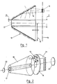
- the implementation of the invention is based on the use of optical parts of conical shape 10 pierced at their center 11.
- Each optical part 10 is advantageously made of a glass material or made of transparent silica at the wavelength of the pump wave emitted by the laser diodes 12 forming a pumping source.
- the central opening 11 makes it possible to insert a laser rod 17 and the clearance 13 existing between the rod 17 and the diameter of the hole 11 can be adjusted so as to allow the flow of a coolant whose hydrodynamic regime can be control.
- a dielectric, multidielectric or metallic coating on the conical part 10 makes it possible to perform the mirror function.
- the pumping in this case is distributed on a plate 14 located in the vicinity of the cross section of larger surface 15 presented by the optical conical part 10 carrying out the transfer of the pump beams 16 to the laser bar.
- These laser diodes 12 located on the same surface 14 allow a specific treatment of the evacuation of calories using the concept of cooling plate and the arrangement of the diodes 12 is carried out in such a way that the pumping of the bar 17 has the best homogeneity.
- the support plate 14 of the pumping diodes 12 is provided with a radiator 21, two mirrors 22, 23 forming the pumping cavity.
- the pumping cavity is independent of the assembly formed by the support 14 provided with the optical sources 12, the reflector 10 and the rod 17.
- the frustoconical reflector 10 forms an optical coupling common to the assembly of the pump, and is inserted between the emissive plate made up of all the laser diodes 12 and the optical transfer part 10.
- FIG. 3 illustrates a configuration adapted to the case represented by the use of a laser bar 30 cut at the Brewster angle, in order to minimize the losses on reflection on each diopter and to control the polarization state of the optical wave generated in the bar 30.
- the rigid assembly 12 + 30 + 14 + 10 is tilted by an angle A between the mirrors 31, 32 of the laser cavity.
- the size of the coupling optics has the particular geometry suitable for the Brewster configuration.
- the configuration of the lighting structure can be used using a mixed pumping mode.
- a power laser diode 41 is coupled to one end of the bar.
- This diode performs the longitudinal pumping and has a beam characteristic adjusted to that of the mode of the cavity in the part of the bar which is closest to it.
- This longitudinal pump can be used to initiate population inversion or to increase the stability of the beam by imposing on a part of the bar a gain profile adjusting to that of the mode of the cavity.
- the laser diode 41 may be replaced by an annex laser of small power but stable in frequency (Seeder), for injecting a control signal.
- the lighting structures 55, 56; 65.66 are mounted head to tail, so that the support plates 57.58; 67.68 optical sources are arranged at the ends of the assembly.
- each of the modules 53,54 is provided with a separate laser bar 51,52.
- the laser bar 51 of the oscillator is associated with a set of reflectors 50, 59 forming the laser cavity.
- the faces of the bar 52 are treated with anti-reflection.
- the reflectors 62, 63 of the pumping cavity are located on either side of the bar 61.
- the source assembly having the character "monoblock" laser bar 61 + coupling optics 65, 66 of the pump
- This rotation of the bar makes it possible to achieve homogenization of the pumping and can play a facilitating role in terms of heat exchange and cooling the bar.
- Rotation is allowed by mounting the rigid assembly on the two plates fixed support 67,68, via ball bearings 69. Cooling is generated by a flow passing through the interior cavities 60, and for example injection or evacuation nozzles 70 formed in the connection structures 71 of the coupling optics 65.66.
- FIG. 7 An embodiment of the invention is shown in FIG. 7.
- the rotational movement is replaced in this case by a translation 72 of the laser plate 73 relative to the transfer optics of the pump 74 and to the defined cavity between the two reflectors 75, 76, which makes it possible to minimize the residual thermal effects. Only one condition governs the use of such a displacement: it is necessary that the laser medium is homogeneous and has a cross section of dimension greater than that of the mode of the cavity.
- the concept of oscillator and amplifier integrated on the same plate 80 can be implemented from a distributed pumping transferred from a set of laser ribbons 83 disposed on the pump plate 81 towards the laser medium 80 via an optical prismatic part 82.
- a first line 84 crossing the plate 80 corresponds to the resonance of the oscillator, between two reflectors 87,88 and a second line 85, returned by a reflective prism 86, corresponds to an amplification stage.
Landscapes
- Physics & Mathematics (AREA)
- Electromagnetism (AREA)
- Engineering & Computer Science (AREA)
- Plasma & Fusion (AREA)
- Optics & Photonics (AREA)
- Lasers (AREA)
Claims (13)
- Anordnung zur Beleuchtung einer Laserplatte, insbesondere für das transversale Pumpen der Platte ausgehend von wenigstens einem Satz von kohärenten Lichtquellen, dadurch gekennzeichnet, daß die Lichtquellen (12) wenigstens eines Lichtquellensatzes auf einem gleichen abgesetzten Träger (81) angeordnet sind, der eine zu der Platte (80) senkrechte Ebene ist, und daß die Anordnung reflektierende Mittel (74; 82) zur Umlenkung des Beleuchtungsbündels des Satzes von abgesetzten Lichtquellen zu der Platte (73; 80) enthält, wobei die Mittel zur Umlenkung des Beleuchtungsbündels durch wenigstens eine geneigte reflektierende ebene Fläche (82) gebildet sind.
- Anordnung nach Anspruch 1, dadurch gekennzeichnet, daß der abgesetzte Träger ein die Wärme abführender Kühlkörper (21) ist, der den Quellen des Lichtquellensatzes gemeinsam ist.
- Anordnung nach Anspruch 1, dadurch gekennzeichnet, daß der mit den Lichtquellen (12) versehene Träger (81), die Umlenkmittel (82) für das Beleuchtungsbündel und die Platte (73, 80) eine starre Baugruppe bilden, wobei die Baugruppe mit einem Paar von Reflektoren (87, 88) zusammenwirkt, die einen Laserhohlraum bilden.
- Anordnung nach Anspruch 3, dadurch gekennzeichnet, daß sie mit einer Steuerquelle und/oder einer Laserdiode (41) für longitudinales Pumpen zusammenwirkt.
- Anordnung nach einem der Ansprüche 1 bis 4, dadurch gekennzeichnet, daß sie einerseits mit einem Paar von Reflektoren (87, 88) zusammenwirkt, die einen Pumphohlraum bilden, und andererseits mit Mitteln (86), die das aus dem Hohlraum austretende Bündel (84) für wenigstens einen zweiten Durchgang (85) in die Platte zurückschicken.
- Anordnung nach einem der Ansprüche 1 bis 5, dadurch gekennzeichnet, daß sie aus zwei nebeneinander montierten Baugruppen gebildet ist, wobei jede Baugruppe aus dem mit den Lichtquellen (12) ausgestatteten Träger (81), den reflektierenden Mitteln (82) zur Umlenkung des Lichtbündels und der Platte (80) gebildet ist.
- Anordnung nach Anspruch 6, dadurch gekennzeichnet, daß die erste Baugruppe einen Oszillator und die zweite Baugruppe einen Verstärker bildet.
- Anordnung nach Anspruch 6, dadurch gekennzeichnet, daß die beiden Baugruppen mit derselben Platte (80) derart zusammenwirken, daß ein Oszillator mit symmetrischem Pumpen gebildet wird.
- Anordnung nach Anspruch 3 und einem der Ansprüche 4 bis 8, dadurch gekennzeichnet, daß sie Mittel (72) zur translatorischen Verstellung der starren Baugruppe in bezug auf den Pumphohlraum (75, 76) im wesentlichen in der Ebene der Platte (73, 80) aufweist.
- Anordnung nach Anspruch 9, dadurch gekennzeichnet, daß der bewegliche Block Mittel zur Erzeugung einer hydrodynamischen Kühlströmung am Ort der Platte (73, 80) enthält.
- Anordnung nach Anspruch 10, dadurch gekennzeichnet, daß die Platte mit dem beweglichen Block fest verbunden ist.
- Anordnung nach einem der Ansprüche 1 bis 11, dadurch gekennzeichnet, daß die kohärenten Lichtquellen (12) durch Laserdioden gebildet sind.
- Anordnung nach einem der Ansprüche 1 bis 12, dadurch gekennzeichnet, daß die reflektierenden Umlenkmittel, die das Beleuchtungsbündel des Satzes von abgesetzten Lichtquellen zu der Platte hin umlenken, durch einen Spiegel mit dielektrischer und/oder metallischer Beschichtung gebildet sind.
Applications Claiming Priority (2)
| Application Number | Priority Date | Filing Date | Title |
|---|---|---|---|
| FR898908384A FR2648962B1 (fr) | 1989-06-23 | 1989-06-23 | Structure d'illumination d'un barreau laser, a sources optiques defocalisees |
| FR8908384 | 1989-06-23 |
Publications (2)
| Publication Number | Publication Date |
|---|---|
| EP0404635A1 EP0404635A1 (de) | 1990-12-27 |
| EP0404635B1 true EP0404635B1 (de) | 1995-09-13 |
Family
ID=9383055
Family Applications (1)
| Application Number | Title | Priority Date | Filing Date |
|---|---|---|---|
| EP90401618A Expired - Lifetime EP0404635B1 (de) | 1989-06-23 | 1990-06-12 | Beleuchtungsstruktur eines Laserstabes mit delokalisierten optischen Quellen |
Country Status (4)
| Country | Link |
|---|---|
| US (1) | US5086433A (de) |
| EP (1) | EP0404635B1 (de) |
| DE (1) | DE69022301T2 (de) |
| FR (1) | FR2648962B1 (de) |
Families Citing this family (33)
| Publication number | Priority date | Publication date | Assignee | Title |
|---|---|---|---|---|
| FR2679050B1 (fr) * | 1991-07-09 | 1994-08-26 | Thomson Csf | Dispositifs d'optique non lineaire. |
| FR2681988A1 (fr) * | 1991-09-27 | 1993-04-02 | Thomson Csf | Laser de puissance a deflexion. |
| US5323414A (en) * | 1992-04-24 | 1994-06-21 | Electro Scientific Industries, Inc. | Laser system and method employing a nonimaging concentrator |
| US5590141A (en) * | 1992-04-24 | 1996-12-31 | Electro Scientific Industries, Inc. | Method and apparatus for generating and employing a high density of excited ions in a lasant |
| US5548608A (en) * | 1993-02-08 | 1996-08-20 | Zhang; Tong | Laser head and telescopic cavity for diode-pumped solid-state lasers |
| IL108439A (en) * | 1994-01-26 | 1998-08-16 | Yeda Res & Dev | Optically pumped laser apparatus |
| FR2725081B1 (fr) * | 1994-09-23 | 1996-11-15 | Thomson Csf | Source optique compacte, basee sur le doublage de frequence d'un laser et auto-stabilisee par depeuplement de la pompe |
| JPH09260754A (ja) * | 1996-03-27 | 1997-10-03 | Mitsubishi Electric Corp | 半導体レーザ励起固体レーザ増幅装置及び半導体レーザ励起固体レーザ装置 |
| JPH10242551A (ja) * | 1997-02-28 | 1998-09-11 | Nikon Corp | 光学素子及びこれを用いたレーザ装置 |
| US5936984A (en) * | 1997-05-21 | 1999-08-10 | Onxy Optics, Inc. | Laser rods with undoped, flanged end-caps for end-pumped laser applications |
| DE19758366B4 (de) * | 1997-12-22 | 2006-08-31 | Forschungsverbund Berlin E.V. | Verfahren und Vorrichtung zum optischen Pumpen von Wellenleiterlasern oder -verstärkern durch von Laserdioden emittiertes Licht |
| JPH11312832A (ja) * | 1998-04-28 | 1999-11-09 | Fuji Photo Film Co Ltd | 半導体レーザ励起固体レーザ |
| FR2784185B1 (fr) | 1998-10-06 | 2001-02-02 | Thomson Csf | Dispositif pour l'harmonisation entre une voie d'emission laser et une voie passive d'observation |
| US6594299B1 (en) * | 1998-11-12 | 2003-07-15 | Mitsubishi Denki Kabushiki Kaisha | Semiconductor laser light emitting apparatus and solid-state laser rod pumping module |
| US7286241B2 (en) * | 1999-06-24 | 2007-10-23 | Lockheed Martin Corporation | System and method for high-speed laser detection of ultrasound |
| US6483859B1 (en) | 1999-06-24 | 2002-11-19 | Lockheed Martin Corporation | System and method for high-speed laser detection of ultrasound |
| FR2796211B1 (fr) | 1999-07-09 | 2001-10-12 | Thomson Csf | Cavite optique instable pour faisceau laser |
| FR2803697B1 (fr) * | 2000-01-06 | 2003-05-30 | Cilas | Element actif pour source laser et source laser comportant un tel element actif |
| FR2811148B1 (fr) | 2000-06-30 | 2006-07-21 | Thomson Csf | Laser pompe et milieu laser optimise |
| FR2814281B1 (fr) * | 2000-09-19 | 2003-08-29 | Thomson Lcd | Matrice active tft pour capteur optique comportant une couche semi-conductrice photosensible, et capteur optique comportant une telle matrice |
| CA2357809A1 (en) * | 2000-11-22 | 2002-05-22 | Photonami Inc. | Multiport optical amplifier and method amplifying optical signals |
| FR2818814B1 (fr) | 2000-12-26 | 2003-02-28 | Cilas | Source laser |
| FR2818813B1 (fr) * | 2000-12-26 | 2005-05-27 | Cilas | Procede pour fabriquer des elements actifs pour source laser |
| FR2825463B1 (fr) * | 2001-05-30 | 2003-09-12 | Thales Sa | Gyrometre laser etat solide comportant un bloc resonateur |
| US6714307B2 (en) | 2001-10-16 | 2004-03-30 | Zygo Corporation | Measurement of complex surface shapes using a spherical wavefront |
| US7126974B1 (en) * | 2003-04-09 | 2006-10-24 | University Of Central Florida Research Foundation, Inc. | Ring geometry diode laser arrays and methods |
| DE10357515B4 (de) * | 2003-12-08 | 2008-04-10 | Eads Deutschland Gmbh | Transversal gepumpter Festkörperlaser mit konusförmigem Wellenleiter |
| US20060039439A1 (en) * | 2004-08-19 | 2006-02-23 | Nettleton John E | Total internal reflecting laser pump cavity |
| DE102007045488B4 (de) * | 2007-09-14 | 2010-07-22 | Heraeus Quarzglas Gmbh & Co. Kg | Seitengepumpter Laser |
| DE102008063829B4 (de) | 2008-12-20 | 2011-01-13 | Heraeus Quarzglas Gmbh & Co. Kg | Verfahren zur Herstellung eines zylinderförmigen optischen Bauteils aus Quarzglas sowie nach dem Verfahren erhaltenes optisch aktives Bauteil |
| DE102009011186A1 (de) * | 2009-03-04 | 2010-09-09 | AALZ Aachener Arbeitskreis für Laser Zahnheilkunde GmbH | Vorrichtung zur Anregung von Lasermedien |
| US20250023315A1 (en) * | 2023-07-12 | 2025-01-16 | National Tsing Hua University | Cone laser-gain module, double-side-pumped cone laser-gain module, cone laser amplifier, and cone laser oscillator |
| WO2025160889A1 (en) * | 2024-02-01 | 2025-08-07 | Ledlas Corp. | Laser pumping device with pump light guided by cooling liquid |
Family Cites Families (8)
| Publication number | Priority date | Publication date | Assignee | Title |
|---|---|---|---|---|
| DE2844129A1 (de) * | 1978-10-10 | 1980-04-24 | Siemens Ag | Longitudinal gepumpter yag zu nd hoch 3+ -faserlaser |
| US4555786A (en) * | 1982-06-24 | 1985-11-26 | Board Of Trustees Of Leland Stanford, Jr. University | High power solid state laser |
| IL72845A0 (en) * | 1983-09-30 | 1984-12-31 | Univ Leland Stanford Junior | Fiber optic amplifier |
| US4642809A (en) * | 1985-02-28 | 1987-02-10 | Rca Corporation | Slab active lasing medium |
| US4713822A (en) * | 1985-05-24 | 1987-12-15 | Amada Engineering & Service Co., Inc. | Laser device |
| GB8630494D0 (en) * | 1986-12-20 | 1987-01-28 | Lumonics Ltd | High power laser |
| US4794615A (en) * | 1987-06-12 | 1988-12-27 | Spectra Diode Laboratories, Inc. | End and side pumped laser |
| US4949346A (en) * | 1989-08-14 | 1990-08-14 | Allied-Signal Inc. | Conductively cooled, diode-pumped solid-state slab laser |
-
1989
- 1989-06-23 FR FR898908384A patent/FR2648962B1/fr not_active Expired - Fee Related
-
1990
- 1990-06-12 EP EP90401618A patent/EP0404635B1/de not_active Expired - Lifetime
- 1990-06-12 DE DE69022301T patent/DE69022301T2/de not_active Expired - Fee Related
- 1990-06-12 US US07/536,523 patent/US5086433A/en not_active Expired - Fee Related
Also Published As
| Publication number | Publication date |
|---|---|
| US5086433A (en) | 1992-02-04 |
| EP0404635A1 (de) | 1990-12-27 |
| DE69022301D1 (de) | 1995-10-19 |
| DE69022301T2 (de) | 1996-02-22 |
| FR2648962B1 (fr) | 1994-09-09 |
| FR2648962A1 (fr) | 1990-12-28 |
Similar Documents
| Publication | Publication Date | Title |
|---|---|---|
| EP0404635B1 (de) | Beleuchtungsstruktur eines Laserstabes mit delokalisierten optischen Quellen | |
| EP0401064B1 (de) | Laser-Dioden-gepumpter Leistungs-Laser | |
| US6243407B1 (en) | High power laser devices | |
| EP0433122B1 (de) | Laservorrichtung mit Ringresonator | |
| US4951294A (en) | Diode pumped modelocked solid state laser | |
| FR2709381A1 (fr) | Oscillateur optique paramétrique à cavité résonante instable. | |
| EP0377206A1 (de) | Optisch gepumpter Slab-Laser mit schmaler Pumpquellen-Emissionsfläche | |
| EP0390662B1 (de) | Hochleistungs-Laser mit Steuerung der Richtung der Ausgangsstrahlung | |
| EP0100089B1 (de) | Laseroszillator mit Gasfluss | |
| FR2665307A1 (fr) | Systeme laser adapte. | |
| EP0493235A1 (de) | Hochenergie-Festkörperlaser | |
| EP4131948A1 (de) | Diodenlichtquelle für einen projektor | |
| EP4165449A1 (de) | Reflektierende optik mit einem kühlsystem | |
| EP2018687A1 (de) | Gepulstes hochleistungs-wellenleiter-lasergerät | |
| EP1166402B1 (de) | Vorrichtung zum optischen pumpen eines lasers, die einen zylindrischen reflektor mit polygonalem quernschnitt enthält | |
| FR2781613A1 (fr) | Laser en espace libre avec sortie fibre autoalignee | |
| FR2460057A1 (fr) | Composants pour lasers | |
| EP1196970B1 (de) | Verfahren zum optischen pumpen eines lichtverstärkenden mediums und modul zur durchführung des verfahrens | |
| FR2785098A1 (fr) | Laser solide pompe par diode laser | |
| FR2818815A1 (fr) | Laser bicadence | |
| FR2909806A1 (fr) | Cristal et source laser a haute energie associe. | |
| FR2853146A1 (fr) | Structure de pompage optique d'un milieu amplificateur | |
| FR2756110A1 (fr) | Oscillateur optique a agilite de pointage et source laser utilisant cet oscillateur optique | |
| EP0767519A1 (de) | Vorrichtung zur optischen Verstärkung | |
| EP0205364A1 (de) | Vorrichtung zur Erzeugung eines Laserbündels |
Legal Events
| Date | Code | Title | Description |
|---|---|---|---|
| PUAI | Public reference made under article 153(3) epc to a published international application that has entered the european phase |
Free format text: ORIGINAL CODE: 0009012 |
|
| AK | Designated contracting states |
Kind code of ref document: A1 Designated state(s): DE GB IT |
|
| 17P | Request for examination filed |
Effective date: 19910322 |
|
| 17Q | First examination report despatched |
Effective date: 19930726 |
|
| RAP1 | Party data changed (applicant data changed or rights of an application transferred) |
Owner name: THOMSON-CSF |
|
| GRAA | (expected) grant |
Free format text: ORIGINAL CODE: 0009210 |
|
| AK | Designated contracting states |
Kind code of ref document: B1 Designated state(s): DE GB IT |
|
| REF | Corresponds to: |
Ref document number: 69022301 Country of ref document: DE Date of ref document: 19951019 |
|
| ITF | It: translation for a ep patent filed | ||
| GBT | Gb: translation of ep patent filed (gb section 77(6)(a)/1977) |
Effective date: 19951116 |
|
| PLBE | No opposition filed within time limit |
Free format text: ORIGINAL CODE: 0009261 |
|
| STAA | Information on the status of an ep patent application or granted ep patent |
Free format text: STATUS: NO OPPOSITION FILED WITHIN TIME LIMIT |
|
| 26N | No opposition filed | ||
| PGFP | Annual fee paid to national office [announced via postgrant information from national office to epo] |
Ref country code: DE Payment date: 20010523 Year of fee payment: 12 |
|
| PGFP | Annual fee paid to national office [announced via postgrant information from national office to epo] |
Ref country code: GB Payment date: 20010524 Year of fee payment: 12 |
|
| REG | Reference to a national code |
Ref country code: GB Ref legal event code: IF02 |
|
| PG25 | Lapsed in a contracting state [announced via postgrant information from national office to epo] |
Ref country code: GB Free format text: LAPSE BECAUSE OF NON-PAYMENT OF DUE FEES Effective date: 20020612 |
|
| PG25 | Lapsed in a contracting state [announced via postgrant information from national office to epo] |
Ref country code: DE Free format text: LAPSE BECAUSE OF NON-PAYMENT OF DUE FEES Effective date: 20030101 |
|
| GBPC | Gb: european patent ceased through non-payment of renewal fee |
Effective date: 20020612 |
|
| PG25 | Lapsed in a contracting state [announced via postgrant information from national office to epo] |
Ref country code: IT Free format text: LAPSE BECAUSE OF NON-PAYMENT OF DUE FEES;WARNING: LAPSES OF ITALIAN PATENTS WITH EFFECTIVE DATE BEFORE 2007 MAY HAVE OCCURRED AT ANY TIME BEFORE 2007. THE CORRECT EFFECTIVE DATE MAY BE DIFFERENT FROM THE ONE RECORDED. Effective date: 20050612 |