EP0404635B1 - Delocalised optical source illumination structure of a rod laser - Google Patents
Delocalised optical source illumination structure of a rod laser Download PDFInfo
- Publication number
- EP0404635B1 EP0404635B1 EP90401618A EP90401618A EP0404635B1 EP 0404635 B1 EP0404635 B1 EP 0404635B1 EP 90401618 A EP90401618 A EP 90401618A EP 90401618 A EP90401618 A EP 90401618A EP 0404635 B1 EP0404635 B1 EP 0404635B1
- Authority
- EP
- European Patent Office
- Prior art keywords
- plate
- structure according
- pumping
- optical sources
- illumination
- Prior art date
- Legal status (The legal status is an assumption and is not a legal conclusion. Google has not performed a legal analysis and makes no representation as to the accuracy of the status listed.)
- Expired - Lifetime
Links
- 230000003287 optical effect Effects 0.000 title claims description 39
- 238000005286 illumination Methods 0.000 title claims description 30
- 238000005086 pumping Methods 0.000 claims description 38
- 230000001427 coherent effect Effects 0.000 claims description 6
- 238000001816 cooling Methods 0.000 claims description 6
- 230000000712 assembly Effects 0.000 claims description 3
- 238000000429 assembly Methods 0.000 claims description 3
- 238000006073 displacement reaction Methods 0.000 claims description 3
- 239000011248 coating agent Substances 0.000 claims description 2
- 238000000576 coating method Methods 0.000 claims description 2
- 230000008878 coupling Effects 0.000 description 5
- 238000010168 coupling process Methods 0.000 description 5
- 238000005859 coupling reaction Methods 0.000 description 5
- VYPSYNLAJGMNEJ-UHFFFAOYSA-N Silicium dioxide Chemical compound O=[Si]=O VYPSYNLAJGMNEJ-UHFFFAOYSA-N 0.000 description 4
- 230000003321 amplification Effects 0.000 description 3
- 230000000694 effects Effects 0.000 description 3
- 238000003199 nucleic acid amplification method Methods 0.000 description 3
- 239000000243 solution Substances 0.000 description 3
- 238000006243 chemical reaction Methods 0.000 description 2
- 239000011521 glass Substances 0.000 description 2
- 238000000034 method Methods 0.000 description 2
- 239000000377 silicon dioxide Substances 0.000 description 2
- 239000007787 solid Substances 0.000 description 2
- 230000000295 complement effect Effects 0.000 description 1
- 239000002826 coolant Substances 0.000 description 1
- 239000013078 crystal Substances 0.000 description 1
- 230000001419 dependent effect Effects 0.000 description 1
- 239000000835 fiber Substances 0.000 description 1
- 238000000265 homogenisation Methods 0.000 description 1
- 238000002347 injection Methods 0.000 description 1
- 239000007924 injection Substances 0.000 description 1
- 150000002500 ions Chemical class 0.000 description 1
- 239000000463 material Substances 0.000 description 1
- 239000013307 optical fiber Substances 0.000 description 1
- 230000010287 polarization Effects 0.000 description 1
- -1 rare earth ions Chemical class 0.000 description 1
- 229910052761 rare earth metal Inorganic materials 0.000 description 1
Images


Classifications
-
- H—ELECTRICITY
- H01—ELECTRIC ELEMENTS
- H01S—DEVICES USING THE PROCESS OF LIGHT AMPLIFICATION BY STIMULATED EMISSION OF RADIATION [LASER] TO AMPLIFY OR GENERATE LIGHT; DEVICES USING STIMULATED EMISSION OF ELECTROMAGNETIC RADIATION IN WAVE RANGES OTHER THAN OPTICAL
- H01S3/00—Lasers, i.e. devices using stimulated emission of electromagnetic radiation in the infrared, visible or ultraviolet wave range
- H01S3/02—Constructional details
- H01S3/04—Arrangements for thermal management
- H01S3/042—Arrangements for thermal management for solid state lasers
-
- H—ELECTRICITY
- H01—ELECTRIC ELEMENTS
- H01S—DEVICES USING THE PROCESS OF LIGHT AMPLIFICATION BY STIMULATED EMISSION OF RADIATION [LASER] TO AMPLIFY OR GENERATE LIGHT; DEVICES USING STIMULATED EMISSION OF ELECTROMAGNETIC RADIATION IN WAVE RANGES OTHER THAN OPTICAL
- H01S3/00—Lasers, i.e. devices using stimulated emission of electromagnetic radiation in the infrared, visible or ultraviolet wave range
- H01S3/09—Processes or apparatus for excitation, e.g. pumping
- H01S3/091—Processes or apparatus for excitation, e.g. pumping using optical pumping
- H01S3/094—Processes or apparatus for excitation, e.g. pumping using optical pumping by coherent light
- H01S3/0941—Processes or apparatus for excitation, e.g. pumping using optical pumping by coherent light of a laser diode
-
- H—ELECTRICITY
- H01—ELECTRIC ELEMENTS
- H01S—DEVICES USING THE PROCESS OF LIGHT AMPLIFICATION BY STIMULATED EMISSION OF RADIATION [LASER] TO AMPLIFY OR GENERATE LIGHT; DEVICES USING STIMULATED EMISSION OF ELECTROMAGNETIC RADIATION IN WAVE RANGES OTHER THAN OPTICAL
- H01S3/00—Lasers, i.e. devices using stimulated emission of electromagnetic radiation in the infrared, visible or ultraviolet wave range
- H01S3/02—Constructional details
- H01S3/025—Constructional details of solid state lasers, e.g. housings or mountings
-
- H—ELECTRICITY
- H01—ELECTRIC ELEMENTS
- H01S—DEVICES USING THE PROCESS OF LIGHT AMPLIFICATION BY STIMULATED EMISSION OF RADIATION [LASER] TO AMPLIFY OR GENERATE LIGHT; DEVICES USING STIMULATED EMISSION OF ELECTROMAGNETIC RADIATION IN WAVE RANGES OTHER THAN OPTICAL
- H01S3/00—Lasers, i.e. devices using stimulated emission of electromagnetic radiation in the infrared, visible or ultraviolet wave range
- H01S3/02—Constructional details
- H01S3/04—Arrangements for thermal management
- H01S3/0404—Air- or gas cooling, e.g. by dry nitrogen
-
- H—ELECTRICITY
- H01—ELECTRIC ELEMENTS
- H01S—DEVICES USING THE PROCESS OF LIGHT AMPLIFICATION BY STIMULATED EMISSION OF RADIATION [LASER] TO AMPLIFY OR GENERATE LIGHT; DEVICES USING STIMULATED EMISSION OF ELECTROMAGNETIC RADIATION IN WAVE RANGES OTHER THAN OPTICAL
- H01S3/00—Lasers, i.e. devices using stimulated emission of electromagnetic radiation in the infrared, visible or ultraviolet wave range
- H01S3/02—Constructional details
- H01S3/04—Arrangements for thermal management
- H01S3/0407—Liquid cooling, e.g. by water
-
- H—ELECTRICITY
- H01—ELECTRIC ELEMENTS
- H01S—DEVICES USING THE PROCESS OF LIGHT AMPLIFICATION BY STIMULATED EMISSION OF RADIATION [LASER] TO AMPLIFY OR GENERATE LIGHT; DEVICES USING STIMULATED EMISSION OF ELECTROMAGNETIC RADIATION IN WAVE RANGES OTHER THAN OPTICAL
- H01S3/00—Lasers, i.e. devices using stimulated emission of electromagnetic radiation in the infrared, visible or ultraviolet wave range
- H01S3/09—Processes or apparatus for excitation, e.g. pumping
- H01S3/091—Processes or apparatus for excitation, e.g. pumping using optical pumping
- H01S3/094—Processes or apparatus for excitation, e.g. pumping using optical pumping by coherent light
- H01S3/094049—Guiding of the pump light
- H01S3/094057—Guiding of the pump light by tapered duct or homogenized light pipe, e.g. for concentrating pump light
-
- H—ELECTRICITY
- H01—ELECTRIC ELEMENTS
- H01S—DEVICES USING THE PROCESS OF LIGHT AMPLIFICATION BY STIMULATED EMISSION OF RADIATION [LASER] TO AMPLIFY OR GENERATE LIGHT; DEVICES USING STIMULATED EMISSION OF ELECTROMAGNETIC RADIATION IN WAVE RANGES OTHER THAN OPTICAL
- H01S3/00—Lasers, i.e. devices using stimulated emission of electromagnetic radiation in the infrared, visible or ultraviolet wave range
- H01S3/10—Controlling the intensity, frequency, phase, polarisation or direction of the emitted radiation, e.g. switching, gating, modulating or demodulating
- H01S3/102—Controlling the intensity, frequency, phase, polarisation or direction of the emitted radiation, e.g. switching, gating, modulating or demodulating by controlling the active medium, e.g. by controlling the processes or apparatus for excitation
- H01S3/1022—Controlling the intensity, frequency, phase, polarisation or direction of the emitted radiation, e.g. switching, gating, modulating or demodulating by controlling the active medium, e.g. by controlling the processes or apparatus for excitation by controlling the optical pumping
Definitions
- Illumination structure of a laser bar with delocalized optical sources.
- the field of the invention is that of power lasers pumped by coherent optical sources, such as laser diodes.
- a transverse pumping mode of solid crystals is used in which rare earth ions are inserted, these ions being the seat of the laser effect.
- the use of resonant pumping made from laser diodes has several advantages, including obtaining a better conversion efficiency of electrical energy into optical energy, and minimization of thermal effects at the level of the bar.
- the laser diodes used typically have optical / electrical conversion efficiencies which do not in practice exceed 50%. It follows that, in pumping operations of laser bars, it is necessary to evacuate the unconverted electrical energy, which is partly transformed into heat at the junction of the laser diodes.
- a configuration for removing calories is based on the use of radiators making up the base of the emission bars.
- the level of energy to be removed is important in the case where it is desired to produce power lasers pumped from laser diodes. This therefore requires the use of bulky radiators which penalize the designer of the laser head in particular when it is sought to achieve a uniform pumping of the whole of the bar from bars distributed around it.
- a solution to this problem consisting in relocating the pumping source (constituted for example by laser diodes) and in employing a multimode optical fiber conveying the pumping intensity towards the active medium.
- the invention aims to provide a new structure with delocalized pumping optical sources, overcoming these drawbacks.
- a first objective of the invention is to provide an illumination structure for a laser bar allowing both good evacuation of the calories released by the coherent optical pumping sources, and good homogeneity of the pumping operations of the bar.
- Another objective of the invention is to provide an illumination structure allowing easy coupling, within the same assembly, of an oscillator module and an amplifier module.
- a complementary objective of the invention is to provide a structure capable of forming a rigid assembly, easily positionable and displaceable, in particular in the pumping cavity and / or with respect to an amplification axis when the structure and the bar are used in amplifiers.
- This objective makes it easy to place the laser transmitter in specific operating or emission configurations, as well as to offer new functionalities for homogenizing the illumination of the bar, optimizing the bar in multi-passages, or again, for example, cooling the bar by generating a hydrodynamic flow.
- an illumination structure of a laser rod in particular for pumping the rod from at least one set of optical sources. coherent, the optical sources of at least one set of optical sources being arranged on the same delocalized support, and said structure comprising reflecting means for returning, towards the bar, the illumination beam of said set of delocalized optical sources.
- the optics for transferring the emission from the optical sources to the bar is constituted by reflecting means, in the form of a block of glass or silica of prismatic shape.
- the structure in the case of a prismatic type bar, provision can be made for the structure to cooperate on the one hand with a pair of reflectors forming a pumping cavity, and on the other hand with return means in the bar, in at least one second passage, of the beam from said cavity. It is also possible to provide that the structure comprises means for translational movement of said rigid assembly with respect to the pumping cavity, substantially in the plane of said bar.
- said bar is preferably mounted integral with said movable block. It can then also be provided that said movable block comprises means for generating a hydrodynamic cooling flow at the level of the bar.
- the support provided with the optical sources, the means for returning the illumination beam, and the bar to form a rigid assembly, said assembly cooperating with a pair of reflectors forming a laser cavity.
- said bar is cut at the Brewster angle, said assembly being inclined relative to the axes of the reflectors of the pumping cavity.
- the structure cooperates with a control source and / or a laser diode for longitudinal pumping.
- each assembly being formed of said support provided with optical sources, reflecting means for returning the optical beam, and the bar, the first assembly forming an oscillator, and the second amplifier assembly.
- the figures represent several embodiments of solid lasers pumped by laser diodes using an optic for transferring the pumping to the amplification medium, based on the same reflecting surface.
- This configuration has the merit of grouping the pump laser diodes on the same plate and moving them away from the medium to be pumped. This has the advantage of being able to deal with the thermal problems of the pump collectively.
- the monolithic aspect of the optical coupling-rod couple also makes it possible to envisage a certain number of variants presented below.
- the implementation of the invention is based on the use of optical parts of conical shape 10 pierced at their center 11.
- Each optical part 10 is advantageously made of a glass material or made of transparent silica at the wavelength of the pump wave emitted by the laser diodes 12 forming a pumping source.
- the central opening 11 makes it possible to insert a laser rod 17 and the clearance 13 existing between the rod 17 and the diameter of the hole 11 can be adjusted so as to allow the flow of a coolant whose hydrodynamic regime can be control.
- a dielectric, multidielectric or metallic coating on the conical part 10 makes it possible to perform the mirror function.
- the pumping in this case is distributed on a plate 14 located in the vicinity of the cross section of larger surface 15 presented by the optical conical part 10 carrying out the transfer of the pump beams 16 to the laser bar.
- These laser diodes 12 located on the same surface 14 allow a specific treatment of the evacuation of calories using the concept of cooling plate and the arrangement of the diodes 12 is carried out in such a way that the pumping of the bar 17 has the best homogeneity.
- the support plate 14 of the pumping diodes 12 is provided with a radiator 21, two mirrors 22, 23 forming the pumping cavity.
- the pumping cavity is independent of the assembly formed by the support 14 provided with the optical sources 12, the reflector 10 and the rod 17.
- the frustoconical reflector 10 forms an optical coupling common to the assembly of the pump, and is inserted between the emissive plate made up of all the laser diodes 12 and the optical transfer part 10.
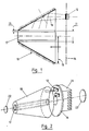
- FIG. 3 illustrates a configuration adapted to the case represented by the use of a laser bar 30 cut at the Brewster angle, in order to minimize the losses on reflection on each diopter and to control the polarization state of the optical wave generated in the bar 30.
- the rigid assembly 12 + 30 + 14 + 10 is tilted by an angle A between the mirrors 31, 32 of the laser cavity.
- the size of the coupling optics has the particular geometry suitable for the Brewster configuration.
- the configuration of the lighting structure can be used using a mixed pumping mode.
- a power laser diode 41 is coupled to one end of the bar.
- This diode performs the longitudinal pumping and has a beam characteristic adjusted to that of the mode of the cavity in the part of the bar which is closest to it.
- This longitudinal pump can be used to initiate population inversion or to increase the stability of the beam by imposing on a part of the bar a gain profile adjusting to that of the mode of the cavity.
- the laser diode 41 may be replaced by an annex laser of small power but stable in frequency (Seeder), for injecting a control signal.
- the lighting structures 55, 56; 65.66 are mounted head to tail, so that the support plates 57.58; 67.68 optical sources are arranged at the ends of the assembly.
- each of the modules 53,54 is provided with a separate laser bar 51,52.
- the laser bar 51 of the oscillator is associated with a set of reflectors 50, 59 forming the laser cavity.
- the faces of the bar 52 are treated with anti-reflection.
- the reflectors 62, 63 of the pumping cavity are located on either side of the bar 61.
- the source assembly having the character "monoblock" laser bar 61 + coupling optics 65, 66 of the pump
- This rotation of the bar makes it possible to achieve homogenization of the pumping and can play a facilitating role in terms of heat exchange and cooling the bar.
- Rotation is allowed by mounting the rigid assembly on the two plates fixed support 67,68, via ball bearings 69. Cooling is generated by a flow passing through the interior cavities 60, and for example injection or evacuation nozzles 70 formed in the connection structures 71 of the coupling optics 65.66.
- FIG. 7 An embodiment of the invention is shown in FIG. 7.
- the rotational movement is replaced in this case by a translation 72 of the laser plate 73 relative to the transfer optics of the pump 74 and to the defined cavity between the two reflectors 75, 76, which makes it possible to minimize the residual thermal effects. Only one condition governs the use of such a displacement: it is necessary that the laser medium is homogeneous and has a cross section of dimension greater than that of the mode of the cavity.
- the concept of oscillator and amplifier integrated on the same plate 80 can be implemented from a distributed pumping transferred from a set of laser ribbons 83 disposed on the pump plate 81 towards the laser medium 80 via an optical prismatic part 82.
- a first line 84 crossing the plate 80 corresponds to the resonance of the oscillator, between two reflectors 87,88 and a second line 85, returned by a reflective prism 86, corresponds to an amplification stage.
Landscapes
- Physics & Mathematics (AREA)
- Electromagnetism (AREA)
- Engineering & Computer Science (AREA)
- Plasma & Fusion (AREA)
- Optics & Photonics (AREA)
- Lasers (AREA)
Description
Le domaine de l'invention est celui des lasers de puissance pompés par des sources optiques cohérentes, telles que des diodes lasers.The field of the invention is that of power lasers pumped by coherent optical sources, such as laser diodes.
Dans le type de structure concerné par l'invention, on utilise un mode de pompage transverse de cristaux solides dans lesquels se trouvent insérés des ions de terres rares, ces ions étant le siège de l'effet laser.In the type of structure concerned by the invention, a transverse pumping mode of solid crystals is used in which rare earth ions are inserted, these ions being the seat of the laser effect.
L'emploi du pompage résonnant réalisé à partir de diodes lasers présente plusieurs avantages, parmi lesquels l'obtention d'un meilleur rendement de conversion de l'énergie électrique en énergie optique, et la minimisation des effets thermiques au niveau du barreau. Cependant, les diodes lasers employées présentent typiquement des rendements de conversion optique/électrique qui n'excèdent pas en pratique 50 %. Il s'ensuit que, dans des opérations de pompage de barreaux lasers, il est nécessaire d'évacuer l'énergie électrique non convertie, qui se transforme en partie en chaleur au niveau de la jonction des diodes lasers.The use of resonant pumping made from laser diodes has several advantages, including obtaining a better conversion efficiency of electrical energy into optical energy, and minimization of thermal effects at the level of the bar. However, the laser diodes used typically have optical / electrical conversion efficiencies which do not in practice exceed 50%. It follows that, in pumping operations of laser bars, it is necessary to evacuate the unconverted electrical energy, which is partly transformed into heat at the junction of the laser diodes.
Une configuration permettant d'évacuer les calories est fondée sur l'emploi de radiateurs composant l'embase des barrettes d'émission. Le niveau d'énergie devant être évacué est important dans le cas où l'on désire réaliser des lasers de puissance pompés à partir de diodes lasers. Ceci nécessite donc l'emploi de radiateurs encombrants qui viennent pénaliser le concepteur de tête laser en particulier lorsque l'on cherche à réaliser un pompage homogène de l'ensemble du barreau à partir de barrettes réparties autour de celui-ci.A configuration for removing calories is based on the use of radiators making up the base of the emission bars. The level of energy to be removed is important in the case where it is desired to produce power lasers pumped from laser diodes. This therefore requires the use of bulky radiators which penalize the designer of the laser head in particular when it is sought to achieve a uniform pumping of the whole of the bar from bars distributed around it.
On connaît une solution à ce problème, consistant à délocaliser la source de pompage (constituées par exemple de diodes lasers) et à employer une fibre optique multimode véhiculant vers le milieu actif l'intensité de pompage.A solution to this problem is known, consisting in relocating the pumping source (constituted for example by laser diodes) and in employing a multimode optical fiber conveying the pumping intensity towards the active medium.
Cette solution ne garantit toutefois pas la meilleure homogénéité dans l'illumination du barreau laser, et suppose en outre l'utilisation d'éléments optiques discrets, coûteux et complexifiant l'opération de montage. Une telle solution est décrite dans le brevet US-A-4 713 822. Une autre méthode d'illumination d'un barreau laser par une source optique non cohérente est décrite dans le document DE-A-2 844 129. Une méthode similaire de pompage d'un amplificateur à fibre optique est décrite dans le document EP-A-0 138 411.This solution does not however guarantee the best homogeneity in the illumination of the laser bar, and also supposes the use of discrete, costly and complexifying optical elements. Such a solution is described in US Pat. No. 4,713,822. Another method of illuminating a laser bar with a non-coherent optical source is described in document DE-A-2,844,129. A similar method of pumping of a fiber optic amplifier is described in document EP-A-0 138 411.
L'invention a pour objectif de fournir une nouvelle structure à sources optiques de pompage délocalisées, palliant ces inconvénients.The invention aims to provide a new structure with delocalized pumping optical sources, overcoming these drawbacks.
Plus précisément, un premier objectif de l'invention est de fournir une structure d'illumination d'un barreau laser permettant à la fois une bonne évacuation des calories dégagées par les sources optiques cohérentes de pompage, et une bonne homogénéité des opérations de pompage du barreau.More specifically, a first objective of the invention is to provide an illumination structure for a laser bar allowing both good evacuation of the calories released by the coherent optical pumping sources, and good homogeneity of the pumping operations of the bar.
Un autre objectif de l'invention est de fournir une structure d'illumination permettant un couplage aisé, au sein d'un même ensemble, d'un module oscillateur et d'un module amplificateur.Another objective of the invention is to provide an illumination structure allowing easy coupling, within the same assembly, of an oscillator module and an amplifier module.
Un objectif complémentaire de l'invention est de fournir une structure susceptible de former un ensemble rigide, aisément positionnable et déplaçable, notamment dans la cavité de pompage et/ou par rapport à un axe d'amplification lorsque la structure et le barreau sont utilisés en amplificateurs. Cet objectif permet de placer aisément l'émetteur laser dans des configurations spécifiques de fonctionnement ou d'émission, ainsi que d'offrir des fonctionnalités nouvelles d'homogénéisation de l'illumination du barreau, d'optimisation du barreau en multi-passages, ou encore, par exemple, de refroidissement du barreau par génération d'un flux hydrodynamique.A complementary objective of the invention is to provide a structure capable of forming a rigid assembly, easily positionable and displaceable, in particular in the pumping cavity and / or with respect to an amplification axis when the structure and the bar are used in amplifiers. This objective makes it easy to place the laser transmitter in specific operating or emission configurations, as well as to offer new functionalities for homogenizing the illumination of the bar, optimizing the bar in multi-passages, or again, for example, cooling the bar by generating a hydrodynamic flow.
Ces objectifs, ainsi que d'autres qui apparaîtront par la suite, sont atteints à l'aide d'une structure d'illumination d'un barreau laser, notamment pour le pompage du barreau à partir d'au moins un jeu de sources optiques cohérentes, les sources optiques d'au moins un jeu de sources optiques étant disposées sur un même support délocalisé, et ladite structure comprenant des moyens réfléchissants de renvoi, vers le barreau, du faisceau d'illumination dudit jeu de sources optiques délocalisées.These objectives, as well as others which will appear subsequently, are achieved using an illumination structure of a laser rod, in particular for pumping the rod from at least one set of optical sources. coherent, the optical sources of at least one set of optical sources being arranged on the same delocalized support, and said structure comprising reflecting means for returning, towards the bar, the illumination beam of said set of delocalized optical sources.
La structure d'illumination selon l'invention est décrite dans la revendication 1. Différents modes de réalisation de l'invention sont décrits dans les revendications dépendantes.The illumination structure according to the invention is described in claim 1. Different embodiments of the invention are described in the dependent claims.
En d'autres termes, l'optique de transfert de l'émission des sources optiques vers le barreau est constituée par des moyens réfléchissants, sous forme d'un bloc de verre ou de silice de forme prismatique.In other words, the optics for transferring the emission from the optical sources to the bar is constituted by reflecting means, in the form of a block of glass or silica of prismatic shape.
Dans le cas d'un barreau de type prismatique, on peut prévoir que la structure coopère d'une part avec une paire de réflecteurs formant cavité de pompage, et d'autre part avec des moyens de renvoi dans le barreau, en au moins un second passage, du faisceau issu de ladite cavité. Il est également possible de prévoir que la structure comprend des moyens de déplacement translatif dudit ensemble rigide par rapport à la cavité de pompage, sensiblement dans le plan dudit barreau.In the case of a prismatic type bar, provision can be made for the structure to cooperate on the one hand with a pair of reflectors forming a pumping cavity, and on the other hand with return means in the bar, in at least one second passage, of the beam from said cavity. It is also possible to provide that the structure comprises means for translational movement of said rigid assembly with respect to the pumping cavity, substantially in the plane of said bar.
Dans ce cas, ledit barreau est monté préférentiellement solidaire audit bloc mobile. On peut alors en outre prévoir que ledit bloc mobile comprend des moyens de génération d'un flux hydrodynamique de refroidissement au niveau du barreau.In this case, said bar is preferably mounted integral with said movable block. It can then also be provided that said movable block comprises means for generating a hydrodynamic cooling flow at the level of the bar.
Dans tous les cas, il est avantageux que le support muni des sources optiques, les moyens de renvoi du faisceau d'illumination, et le barreau forment un ensemble rigide, ledit ensemble coopérant avec une paire de réflecteurs formant cavité laser.In all cases, it is advantageous for the support provided with the optical sources, the means for returning the illumination beam, and the bar to form a rigid assembly, said assembly cooperating with a pair of reflectors forming a laser cavity.
Dans un mode de réalisation spécifique de l'invention, ledit barreau est taillé à l'angle de Brewster, ledit ensemble étant incliné par rapport aux axes des réflecteurs de la cavité de pompage.In a specific embodiment of the invention, said bar is cut at the Brewster angle, said assembly being inclined relative to the axes of the reflectors of the pumping cavity.
Dans un autre mode de réalisation spécifique, la structure coopère avec une source de commande et/ou une diode laser de pompage longitudinal.In another specific embodiment, the structure cooperates with a control source and / or a laser diode for longitudinal pumping.
Il est également possible de réaliser une structure constituée de deux ensembles montés tête-bêche, chaque ensemble étant formé dudit support muni des sources optiques, des moyens réfléchissants de renvoi du faisceau optique, et du barreau, le premier ensemble formant oscillateur, et le second ensemble formant amplificateur.It is also possible to produce a structure consisting of two assemblies mounted head to tail, each assembly being formed of said support provided with optical sources, reflecting means for returning the optical beam, and the bar, the first assembly forming an oscillator, and the second amplifier assembly.
D'autres caractéristiques et avantages de l'invention apparaîtront à la lecture de la description suivantes de mode de réalisation donnés à titre illustratif et non limitatif, et des dessins annexés dans lesquels :
- la figure 1 schématise une coupe d'une structure d'illumination tronconique
- la figure 2 est une vue en perspective d'un oscillateur comprenant la structure d'illumination de la figure 1 placée dans une cavité de pompage
- la figure 3 illustre l'utilisation d'une configuration "Brewster"
- la figure 4 est une vue en coupe illustrant l'utilisation d'une diode laser de pompage longitudinal en combinaison avec une structure d'illumination tronconique
- la figure 5 représente la combinaison de deux structures d'illumination pour former un oscillateur et un amplificateur
- la figure 6 schématise un montage d'oscillateur avec pompage symétrique au moyen de deux structures d'illumination
- la figure 7 représente un mode de réalisation d'une structure d'illumination prismatique selon l'invention, à déplacement de translation par rapport à la cavité de pompage
- la figure 8 illustre un mode de réalisation d'une structure d'illumination prismatique selon l'invention, avec oscillateur et amplificateur conjugués dans la même plaque.
- Figure 1 shows schematically a section of a frustoconical illumination structure
- Figure 2 is a perspective view of an oscillator comprising the illumination structure of Figure 1 placed in a pumping cavity
- Figure 3 illustrates the use of a "Brewster" configuration
- Figure 4 is a sectional view illustrating the use of a longitudinal pump laser diode in combination with a frusto-conical illumination structure
- FIG. 5 represents the combination of two illumination structures to form an oscillator and an amplifier
- Figure 6 shows schematically an oscillator assembly with symmetrical pumping by means of two illumination structures
- FIG. 7 represents an embodiment of a prismatic illumination structure according to the invention, with translational displacement relative to the pumping cavity
- FIG. 8 illustrates an embodiment of a prismatic illumination structure according to the invention, with an oscillator and an amplifier combined in the same plate.
Les figures représentent plusieurs modes de réalisation de lasers solides pompés par diodes lasers utilisant une optique de transfert du pompage vers le milieu d'amplification, à base d'une même surface réfléchissante.The figures represent several embodiments of solid lasers pumped by laser diodes using an optic for transferring the pumping to the amplification medium, based on the same reflecting surface.
Cette configuration a pour mérite de regrouper les diodes lasers de pompe sur une même plaque et d'éloigner celles-ci du milieu devant être pompé. Ceci présente l'avantage de pouvoir traiter les problèmes thermiques de la pompe d'une façon collective. L'aspect monolithique du couple optique de couplage-barreau permet de plus d'envisager un certain nombre de variantes présentées ci-après.This configuration has the merit of grouping the pump laser diodes on the same plate and moving them away from the medium to be pumped. This has the advantage of being able to deal with the thermal problems of the pump collectively. The monolithic aspect of the optical coupling-rod couple also makes it possible to envisage a certain number of variants presented below.
Dans le mode de réalisation non revendiqué représenté en fig 1, la mise en oeuvre de l'invention repose sur l'emploi des pièces optiques de forme conique 10 percées en leur centre 11. Chaque pièce optique 10 est avantageusement réalisée dans un matériau en verre ou en silice transparent à la longueur d'onde de l'onde de pompe émise par les diodes lasers 12 formant source de pompage. L'ouverture centrale 11 permet d'insérer un barreau laser 17 et le jeu 13 existant entre le barreau 17 et le diamètre du trou 11 peut être ajusté de façon à permettre l'écoulement d'un liquide de refroidissement dont le régime hydrodynamique peut être contrôlé. Un revêtement diélectrique, multidïélectrique ou métallique sur la partie conique 10 permet de réaliser la fonction de miroir. Le pompage dans ce cas est réparti sur une plaque 14 située au voisinage de la section droite de plus grande surface 15 présentée par la pièce conique optique 10 réalisant le transfert des faisceaux de pompe 16 vers le barreau laser. Ces diodes lasers 12 localisées sur une même surface 14 permettent un traitement spécifique de l'évacuation des calories en utilisant le concept de plaque de refroidissement et la disposition des diodes 12 est réalisée de telle manière que le pompage du barreau 17 présente la meilleure homogénéité.In the unclaimed embodiment represented in FIG. 1, the implementation of the invention is based on the use of optical parts of
Comme représenté en fig 2, la plaque support 14 des diodes de pompage 12 est munie d'un radiateur 21, deux miroirs 22, 23 formant la cavité de pompage. La cavité de pompage est indépendante de l'ensemble formé par le support 14 muni des sources optiques 12, le réflecteur 10 et le barreau 17. Le réflecteur tronconique 10 forme optique de couplage commune à l'ensemble de la pompe, et est inséré entre la plaque émissive constituée de l'ensemble des diodes lasers 12 et la partie optique de transfert 10.As shown in fig 2, the
La figure 3 illustre une configuration adaptée au cas représenté par l'emploi d'un barreau laser 30 taillé à l'angle de Brewster, dans le but de minimiser les pertes à la réflexion sur chaque dioptre et de contrôler l'état de polarisation de l'onde optique générée dans le barreau 30. Dans ce cas l'ensemble rigide 12 + 30 + 14 + 10 est basculé d'un angle A entre les miroirs 31,32 de la cavité laser. La taille de l'optique de couplage présente la géométrie particulière adéquate à la configuration Brewster.FIG. 3 illustrates a configuration adapted to the case represented by the use of a
La configuration de la structure d'illumination peut être employée en utilisant un mode de pompage mixte. Dans ce cas, comme représenté en fig 4, une diode laser 41 de puissance est couplée à une extrémité du barreau. Cette diode réalise le pompage longitudinal et présente une caractéristique de faisceau ajustée à celle du mode de la cavité dans la partie du barreau qui lui est la plus proche. Cette pompe longitudinale peut être employée pour initier l'inversion de population ou pour accroître la stabilité du faisceau en imposant sur une partie du barreau un profil de gain s'ajustant à celui du mode de la cavité. Le cas échéant la diode laser 41 peut-être remplacée par un laser annexe de petite puissance mais stable en fréquence (Seeder), d'injection d'un signal de commande.The configuration of the lighting structure can be used using a mixed pumping mode. In this case, as shown in FIG. 4, a
L'association de deux structures d'illumination permet de réaliser un montage constitué d'un oscillateur 53 et d'un amplificateur 54 (fig 5) ou d'un oscillateur unique avec un pompage symétrique (fig 6).The association of two illumination structures makes it possible to produce a circuit consisting of an
Les structures d'illuminations 55, 56; 65,66 sont montées têtes-bêche, de façon que les plaques-support 57,58; 67,68 des sources optiques soient disposées aux extrémités de l'ensemble.The
Dans le cas de l'ensemble oscillateur 53 + amplificateur 54 (fig 5), chacun des modules 53,54 est muni d'un barreau laser distinct 51,52. Le barreau laser 51 de l'oscillateur est associé à un jeu de réflecteurs 50,59 formant la cavité laser. Les faces du barreau 52 sont traitées anti-reflets.In the case of the
Dans le mode de réalisation de la figure 6, les réflecteurs 62, 63 de la cavité de pompage sont situées de part et d'autre du barreau 61. Dans ce cas, l'ensemble source ayant le caractère "monobloc" (barreau laser 61 + optique de couplage 65, 66 de la pompe) peut-être animé d'un mouvement de rotation 64. Cette mise en rotation du barreau permet de réaliser une homogénéisation du pompage et peut jouer un rôle facilitant au niveau de l'échange thermique et du refroidissement du barreau.In the embodiment of Figure 6, the
La rotation est autorisée en montant l'ensemble rigide sur les deux plaques support fixes 67,68, par l'intermédiaire des roulements à billes 69. Le refroidissement est généré par un flux traversant les cavité intérieures 60, et par exemple des buses d'injection ou d'évacuation 70 ménagées dans les structures de liaison 71 des optiques de couplage 65,66.Rotation is allowed by mounting the rigid assembly on the two plates fixed
Un mode de réalisation de l'invention est représenté sur la figure 7. Le mouvement de rotation est remplacé dans ce cas par une translation 72 de la plaque laser 73 par rapport à l'optique de transfert de la pompe 74 et à la cavité définie entre les deux réflecteurs 75, 76, ce qui permet de minimiser les effets thermiques résiduels. Une seule condition gouverne l'emploi d'un tel déplacement : il est nécessaire que le milieu laser soit homogène et présente une section droite de dimension supérieure à celle du mode de la cavité.An embodiment of the invention is shown in FIG. 7. The rotational movement is replaced in this case by a
Enfin comme illustré en figure 8 le concept d'oscillateur et d'amplificateur intégré sur une même plaque 80 peut-être mis en oeuvre à partir d'un pompage réparti transféré d'un ensemble de rubans lasers 83 disposé sur la plaque de pompe 81 vers le milieu laser 80 par l'intermédiaire d'une pièce optique 82 prismatique.Finally, as illustrated in FIG. 8, the concept of oscillator and amplifier integrated on the
Ainsi, une première ligne 84 de traversée de la plaque 80 correspond à la mise en résonance de l'oscillateur, entre deux réflecteurs 87,88 et une seconde ligne 85, renvoyée par un prisme réflecteur 86, correspond à un étage d'amplification.Thus, a
Le choix de la pente caractérisant l'inclinaison du dioptre et donc la loi de réflexion et la propagation des faisceaux de pompe, ainsi que le milieu optique de transfert caractérisé par son indice optique, permettent de réaliser un mode de pompage réparti pouvant être sélectif spatialement.The choice of the slope characterizing the inclination of the diopter and therefore the law of reflection and the propagation of the pump beams, as well as the optical transfer medium characterized by its optical index, make it possible to achieve a distributed pumping mode which can be spatially selective .
Claims (13)
- Illumination structure for a laser plate, especially for transverse pumping of the plate from at least one set of coherent optical sources, characterized in that the optical sources (12) of at least one set of optical sources are arranged on the same delocalized support (81), which is a plane perpendicular to the plate (80), and in that the said structure comprises reflecting means (74; 82) for sending back the beam of illumination from the said set of delocalized optical sources towards the plate (73; 80), the said means for sending back the beam of illumination consisting of at least one reflecting inclined plane surface (82).
- Structure according to Claim 1, characterized in that the said delocalized support is a radiator removing the heat (21), common to the sources of the said set of optical sources.
- Structure according to Claim 1, characterized in that the support (81) equipped with the optical sources (12), the means (82) for sending back the beam of illumination, and the plate (73, 80) form a rigid assembly, the said assembly interacting with a pair of reflectors (87, 88) forming a laser cavity.
- Structure according to Claim 3, characterized in that it interacts with a control source and/or a laser diode (41) for longitudinal pumping.
- Structure according to one of Claims 1 to 4, characterized in that it interacts, on the one hand, with a pair of reflectors (87, 88) forming a pumping cavity, and, on the other hand, with means (86) for sending back the beam (84) coming from the said cavity into the plate, in at least a second pass (85).
- Structure according to any one of Claims 1 to 5, characterized in that it consists of two assemblies mounted side by side, each assembly being formed by the said support (81) equipped with the optical sources (12), by reflecting means (82) for sending back the optical beam, and by the plate (80).
- Structure according to Claim 6, characterized in that the first assembly forms an oscillator, and the second assembly forms an amplifier.
- Structure according to Claim 6, characterized in that the two assemblies interact with the same plate (80), so as to form an oscillator with symmetric pumping.
- Structure according to Claim 3 and any one of Claims 4 to 8, characterized in that it comprises means for translative displacement (72) of the said rigid assembly with respect to the pumping cavity (75, 76), substantially in the plane of the plate (73, 80).
- Structure according to Claim 9, characterized in that the said movable unit comprises means for generating a hydrodynamic cooling flow in the region of the plate (73, 80).
- Structure according to Claim 10, characterized in that the said plate is mounted integral with the said movable unit.
- Structure according to any one of Claims 1 to 11, characterized in that the said coherent optical sources (12) consist of laser diodes.
- Structure according to any one of Claims 1 to 12, characterized in that the said reflecting means for sending back the beam of illumination from the said set of delocalized optical sources towards the plate consist of a mirror with a dielectric and/or metallic coating.
Applications Claiming Priority (2)
| Application Number | Priority Date | Filing Date | Title |
|---|---|---|---|
| FR898908384A FR2648962B1 (en) | 1989-06-23 | 1989-06-23 | ILLUMINATION STRUCTURE OF A LASER BAR, WITH DEFOCALIZED OPTICAL SOURCES |
| FR8908384 | 1989-06-23 |
Publications (2)
| Publication Number | Publication Date |
|---|---|
| EP0404635A1 EP0404635A1 (en) | 1990-12-27 |
| EP0404635B1 true EP0404635B1 (en) | 1995-09-13 |
Family
ID=9383055
Family Applications (1)
| Application Number | Title | Priority Date | Filing Date |
|---|---|---|---|
| EP90401618A Expired - Lifetime EP0404635B1 (en) | 1989-06-23 | 1990-06-12 | Delocalised optical source illumination structure of a rod laser |
Country Status (4)
| Country | Link |
|---|---|
| US (1) | US5086433A (en) |
| EP (1) | EP0404635B1 (en) |
| DE (1) | DE69022301T2 (en) |
| FR (1) | FR2648962B1 (en) |
Families Citing this family (33)
| Publication number | Priority date | Publication date | Assignee | Title |
|---|---|---|---|---|
| FR2679050B1 (en) * | 1991-07-09 | 1994-08-26 | Thomson Csf | NON-LINEAR OPTICAL DEVICES. |
| FR2681988A1 (en) * | 1991-09-27 | 1993-04-02 | Thomson Csf | DEFLECTION POWER LASER. |
| US5323414A (en) * | 1992-04-24 | 1994-06-21 | Electro Scientific Industries, Inc. | Laser system and method employing a nonimaging concentrator |
| US5590141A (en) * | 1992-04-24 | 1996-12-31 | Electro Scientific Industries, Inc. | Method and apparatus for generating and employing a high density of excited ions in a lasant |
| US5548608A (en) * | 1993-02-08 | 1996-08-20 | Zhang; Tong | Laser head and telescopic cavity for diode-pumped solid-state lasers |
| IL108439A (en) * | 1994-01-26 | 1998-08-16 | Yeda Res & Dev | Optically pumped laser apparatus |
| FR2725081B1 (en) * | 1994-09-23 | 1996-11-15 | Thomson Csf | COMPACT OPTICAL SOURCE, BASED ON THE FREQUENCY DOUBLING OF A LASER AND SELF-STABILIZED BY PUMP DEPOPE |
| JPH09260754A (en) * | 1996-03-27 | 1997-10-03 | Mitsubishi Electric Corp | Semiconductor laser-pumped solid-state laser amplifier and semiconductor laser-pumped solid-state laser |
| JPH10242551A (en) * | 1997-02-28 | 1998-09-11 | Nikon Corp | Optical element and laser device using the same |
| US5936984A (en) * | 1997-05-21 | 1999-08-10 | Onxy Optics, Inc. | Laser rods with undoped, flanged end-caps for end-pumped laser applications |
| DE19758366B4 (en) * | 1997-12-22 | 2006-08-31 | Forschungsverbund Berlin E.V. | Method and apparatus for optically pumping waveguide lasers or amplifiers by light emitted by laser diodes |
| JPH11312832A (en) * | 1998-04-28 | 1999-11-09 | Fuji Photo Film Co Ltd | Semiconductor-laser exciting solid laser |
| FR2784185B1 (en) | 1998-10-06 | 2001-02-02 | Thomson Csf | DEVICE FOR THE HARMONIZATION BETWEEN A LASER EMISSION CHANNEL AND A PASSIVE OBSERVATION CHANNEL |
| US6594299B1 (en) * | 1998-11-12 | 2003-07-15 | Mitsubishi Denki Kabushiki Kaisha | Semiconductor laser light emitting apparatus and solid-state laser rod pumping module |
| US7286241B2 (en) * | 1999-06-24 | 2007-10-23 | Lockheed Martin Corporation | System and method for high-speed laser detection of ultrasound |
| US6483859B1 (en) | 1999-06-24 | 2002-11-19 | Lockheed Martin Corporation | System and method for high-speed laser detection of ultrasound |
| FR2796211B1 (en) | 1999-07-09 | 2001-10-12 | Thomson Csf | UNSTABLE OPTICAL CAVITY FOR LASER BEAM |
| FR2803697B1 (en) * | 2000-01-06 | 2003-05-30 | Cilas | ACTIVE ELEMENT FOR LASER SOURCE AND LASER SOURCE HAVING SUCH AN ACTIVE ELEMENT |
| FR2811148B1 (en) | 2000-06-30 | 2006-07-21 | Thomson Csf | PUMP LASER AND OPTIMIZED LASER MEDIA |
| FR2814281B1 (en) * | 2000-09-19 | 2003-08-29 | Thomson Lcd | ACTIVE TFT MATRIX FOR OPTICAL SENSOR COMPRISING A PHOTOSENSITIVE SEMICONDUCTOR LAYER, AND OPTICAL SENSOR COMPRISING SUCH A MATRIX |
| CA2357809A1 (en) * | 2000-11-22 | 2002-05-22 | Photonami Inc. | Multiport optical amplifier and method amplifying optical signals |
| FR2818814B1 (en) | 2000-12-26 | 2003-02-28 | Cilas | LASER SOURCE |
| FR2818813B1 (en) * | 2000-12-26 | 2005-05-27 | Cilas | PROCESS FOR PRODUCING ACTIVE ELEMENTS FOR LASER SOURCE |
| FR2825463B1 (en) * | 2001-05-30 | 2003-09-12 | Thales Sa | SOLID STATE LASER GYROMETER COMPRISING A RESONATOR BLOCK |
| US6714307B2 (en) | 2001-10-16 | 2004-03-30 | Zygo Corporation | Measurement of complex surface shapes using a spherical wavefront |
| US7126974B1 (en) * | 2003-04-09 | 2006-10-24 | University Of Central Florida Research Foundation, Inc. | Ring geometry diode laser arrays and methods |
| DE10357515B4 (en) * | 2003-12-08 | 2008-04-10 | Eads Deutschland Gmbh | Transversally pumped solid-state laser with cone-shaped waveguide |
| US20060039439A1 (en) * | 2004-08-19 | 2006-02-23 | Nettleton John E | Total internal reflecting laser pump cavity |
| DE102007045488B4 (en) * | 2007-09-14 | 2010-07-22 | Heraeus Quarzglas Gmbh & Co. Kg | Side pumped laser |
| DE102008063829B4 (en) | 2008-12-20 | 2011-01-13 | Heraeus Quarzglas Gmbh & Co. Kg | Method for producing a cylindrical optical component made of quartz glass and optically active component obtained by the method |
| DE102009011186A1 (en) * | 2009-03-04 | 2010-09-09 | AALZ Aachener Arbeitskreis für Laser Zahnheilkunde GmbH | Device for exciting laser media for producing laser module that is applied e.g. during minimal invasive surgery in dental field, has reflection unit transforming coupled pumping radiation into elongated form on laser-active medium |
| US20250023315A1 (en) * | 2023-07-12 | 2025-01-16 | National Tsing Hua University | Cone laser-gain module, double-side-pumped cone laser-gain module, cone laser amplifier, and cone laser oscillator |
| WO2025160889A1 (en) * | 2024-02-01 | 2025-08-07 | Ledlas Corp. | Laser pumping device with pump light guided by cooling liquid |
Family Cites Families (8)
| Publication number | Priority date | Publication date | Assignee | Title |
|---|---|---|---|---|
| DE2844129A1 (en) * | 1978-10-10 | 1980-04-24 | Siemens Ag | Fibre laser with doped yttrium-aluminium garnet fibre - has LED and two mirrors surrounded by sheath and sleeve |
| US4555786A (en) * | 1982-06-24 | 1985-11-26 | Board Of Trustees Of Leland Stanford, Jr. University | High power solid state laser |
| IL72845A0 (en) * | 1983-09-30 | 1984-12-31 | Univ Leland Stanford Junior | Fiber optic amplifier |
| US4642809A (en) * | 1985-02-28 | 1987-02-10 | Rca Corporation | Slab active lasing medium |
| US4713822A (en) * | 1985-05-24 | 1987-12-15 | Amada Engineering & Service Co., Inc. | Laser device |
| GB8630494D0 (en) * | 1986-12-20 | 1987-01-28 | Lumonics Ltd | High power laser |
| US4794615A (en) * | 1987-06-12 | 1988-12-27 | Spectra Diode Laboratories, Inc. | End and side pumped laser |
| US4949346A (en) * | 1989-08-14 | 1990-08-14 | Allied-Signal Inc. | Conductively cooled, diode-pumped solid-state slab laser |
-
1989
- 1989-06-23 FR FR898908384A patent/FR2648962B1/en not_active Expired - Fee Related
-
1990
- 1990-06-12 EP EP90401618A patent/EP0404635B1/en not_active Expired - Lifetime
- 1990-06-12 DE DE69022301T patent/DE69022301T2/en not_active Expired - Fee Related
- 1990-06-12 US US07/536,523 patent/US5086433A/en not_active Expired - Fee Related
Also Published As
| Publication number | Publication date |
|---|---|
| US5086433A (en) | 1992-02-04 |
| EP0404635A1 (en) | 1990-12-27 |
| DE69022301D1 (en) | 1995-10-19 |
| DE69022301T2 (en) | 1996-02-22 |
| FR2648962B1 (en) | 1994-09-09 |
| FR2648962A1 (en) | 1990-12-28 |
Similar Documents
| Publication | Publication Date | Title |
|---|---|---|
| EP0404635B1 (en) | Delocalised optical source illumination structure of a rod laser | |
| EP0401064B1 (en) | Power laser pumped by laser diodes | |
| US6243407B1 (en) | High power laser devices | |
| EP0433122B1 (en) | Laser device with ring resonator | |
| US4951294A (en) | Diode pumped modelocked solid state laser | |
| FR2709381A1 (en) | Parametric optical oscillator with unstable resonant cavity. | |
| EP0377206A1 (en) | Slab laser optically pumped by a source with a narrow emitting surface | |
| EP0390662B1 (en) | High power laser with output direction control | |
| EP0100089B1 (en) | Laser oscillator with gas flow | |
| FR2665307A1 (en) | ADAPTIVE LASER SYSTEM. | |
| EP0493235A1 (en) | High energy solid state laser | |
| EP4131948A1 (en) | Light source with diodes for headlight | |
| EP4165449A1 (en) | Reflective optics equipped with a cooling system | |
| EP2018687A1 (en) | High-power fiberoptic pulsed laser device | |
| EP1166402B1 (en) | Optical pumping module of a laser comprising a cylindrical reflector with polygonal base | |
| FR2781613A1 (en) | FREE SPACE LASER WITH SELF-ALIGNED FIBER OUTPUT | |
| FR2460057A1 (en) | COMPONENTS FOR LASERS | |
| EP1196970B1 (en) | Method for optical pumping of a light-amplifying medium and optical pumping module for implementing said method | |
| FR2785098A1 (en) | Laser doubler modular laser architecture comprises folded construction active laser regions single pump beam fed using progressive reflections | |
| FR2818815A1 (en) | Telemetry and imaging laser capable of emitting high and low frequencies, has central laser area and first and second pump devices operating at optimized high and low frequencies | |
| FR2909806A1 (en) | Doped laser crystal for e.g. high energy laser source, has main surfaces, outer peripheral surface and radial slot, where surfaces are covered with reflective coating, and circular section bore passing via axis of disk | |
| FR2853146A1 (en) | OPTICAL PUMPING STRUCTURE OF AN AMPLIFIER MEDIUM | |
| FR2756110A1 (en) | Optical oscillator with spatially modulated cavity laser for telemetry esp. in automobile | |
| EP0767519A1 (en) | Device for optical amplification | |
| EP0205364A1 (en) | Device for producing a laser beam |
Legal Events
| Date | Code | Title | Description |
|---|---|---|---|
| PUAI | Public reference made under article 153(3) epc to a published international application that has entered the european phase |
Free format text: ORIGINAL CODE: 0009012 |
|
| AK | Designated contracting states |
Kind code of ref document: A1 Designated state(s): DE GB IT |
|
| 17P | Request for examination filed |
Effective date: 19910322 |
|
| 17Q | First examination report despatched |
Effective date: 19930726 |
|
| RAP1 | Party data changed (applicant data changed or rights of an application transferred) |
Owner name: THOMSON-CSF |
|
| GRAA | (expected) grant |
Free format text: ORIGINAL CODE: 0009210 |
|
| AK | Designated contracting states |
Kind code of ref document: B1 Designated state(s): DE GB IT |
|
| REF | Corresponds to: |
Ref document number: 69022301 Country of ref document: DE Date of ref document: 19951019 |
|
| ITF | It: translation for a ep patent filed | ||
| GBT | Gb: translation of ep patent filed (gb section 77(6)(a)/1977) |
Effective date: 19951116 |
|
| PLBE | No opposition filed within time limit |
Free format text: ORIGINAL CODE: 0009261 |
|
| STAA | Information on the status of an ep patent application or granted ep patent |
Free format text: STATUS: NO OPPOSITION FILED WITHIN TIME LIMIT |
|
| 26N | No opposition filed | ||
| PGFP | Annual fee paid to national office [announced via postgrant information from national office to epo] |
Ref country code: DE Payment date: 20010523 Year of fee payment: 12 |
|
| PGFP | Annual fee paid to national office [announced via postgrant information from national office to epo] |
Ref country code: GB Payment date: 20010524 Year of fee payment: 12 |
|
| REG | Reference to a national code |
Ref country code: GB Ref legal event code: IF02 |
|
| PG25 | Lapsed in a contracting state [announced via postgrant information from national office to epo] |
Ref country code: GB Free format text: LAPSE BECAUSE OF NON-PAYMENT OF DUE FEES Effective date: 20020612 |
|
| PG25 | Lapsed in a contracting state [announced via postgrant information from national office to epo] |
Ref country code: DE Free format text: LAPSE BECAUSE OF NON-PAYMENT OF DUE FEES Effective date: 20030101 |
|
| GBPC | Gb: european patent ceased through non-payment of renewal fee |
Effective date: 20020612 |
|
| PG25 | Lapsed in a contracting state [announced via postgrant information from national office to epo] |
Ref country code: IT Free format text: LAPSE BECAUSE OF NON-PAYMENT OF DUE FEES;WARNING: LAPSES OF ITALIAN PATENTS WITH EFFECTIVE DATE BEFORE 2007 MAY HAVE OCCURRED AT ANY TIME BEFORE 2007. THE CORRECT EFFECTIVE DATE MAY BE DIFFERENT FROM THE ONE RECORDED. Effective date: 20050612 |