EP0404613B1 - Schalthebel für Schaltgetriebe eines Kraftfahrzeuges und Verfahren zu dessen Herstellung - Google Patents
Schalthebel für Schaltgetriebe eines Kraftfahrzeuges und Verfahren zu dessen Herstellung Download PDFInfo
- Publication number
- EP0404613B1 EP0404613B1 EP19900401422 EP90401422A EP0404613B1 EP 0404613 B1 EP0404613 B1 EP 0404613B1 EP 19900401422 EP19900401422 EP 19900401422 EP 90401422 A EP90401422 A EP 90401422A EP 0404613 B1 EP0404613 B1 EP 0404613B1
- Authority
- EP
- European Patent Office
- Prior art keywords
- lever
- fact
- rod
- gearbox
- constituted
- Prior art date
- Legal status (The legal status is an assumption and is not a legal conclusion. Google has not performed a legal analysis and makes no representation as to the accuracy of the status listed.)
- Expired - Lifetime
Links
- 238000004519 manufacturing process Methods 0.000 title claims description 10
- 238000000034 method Methods 0.000 title claims description 9
- 239000000463 material Substances 0.000 claims description 21
- 239000004033 plastic Substances 0.000 claims description 20
- 229920003023 plastic Polymers 0.000 claims description 20
- 238000000465 moulding Methods 0.000 claims description 16
- 238000002347 injection Methods 0.000 claims description 9
- 239000007924 injection Substances 0.000 claims description 9
- 238000001746 injection moulding Methods 0.000 claims description 6
- 230000005540 biological transmission Effects 0.000 claims description 5
- 239000004952 Polyamide Substances 0.000 claims description 4
- 229920002647 polyamide Polymers 0.000 claims description 4
- 229930182556 Polyacetal Natural products 0.000 claims description 3
- 229920006324 polyoxymethylene Polymers 0.000 claims description 3
- 239000004800 polyvinyl chloride Substances 0.000 claims description 3
- 229920000915 polyvinyl chloride Polymers 0.000 claims description 3
- 210000002105 tongue Anatomy 0.000 claims description 3
- 229920001169 thermoplastic Polymers 0.000 claims 2
- 239000004416 thermosoftening plastic Substances 0.000 claims 2
- 238000010276 construction Methods 0.000 claims 1
- 239000011152 fibreglass Substances 0.000 claims 1
- 230000014759 maintenance of location Effects 0.000 claims 1
- 239000002184 metal Substances 0.000 description 9
- 239000012815 thermoplastic material Substances 0.000 description 7
- 230000009467 reduction Effects 0.000 description 3
- 239000003365 glass fiber Substances 0.000 description 2
- 239000005060 rubber Substances 0.000 description 2
- 238000003466 welding Methods 0.000 description 2
- 235000008612 Gnetum gnemon Nutrition 0.000 description 1
- 240000000018 Gnetum gnemon Species 0.000 description 1
- 230000009471 action Effects 0.000 description 1
- 239000004020 conductor Substances 0.000 description 1
- 239000000835 fiber Substances 0.000 description 1
- 239000011521 glass Substances 0.000 description 1
- 230000006872 improvement Effects 0.000 description 1
- 238000009776 industrial production Methods 0.000 description 1
- 238000012423 maintenance Methods 0.000 description 1
- 230000008569 process Effects 0.000 description 1
- 230000001681 protective effect Effects 0.000 description 1
- 239000007787 solid Substances 0.000 description 1
- 230000004584 weight gain Effects 0.000 description 1
- 235000019786 weight gain Nutrition 0.000 description 1
Images



Classifications
-
- B—PERFORMING OPERATIONS; TRANSPORTING
- B60—VEHICLES IN GENERAL
- B60K—ARRANGEMENT OR MOUNTING OF PROPULSION UNITS OR OF TRANSMISSIONS IN VEHICLES; ARRANGEMENT OR MOUNTING OF PLURAL DIVERSE PRIME-MOVERS IN VEHICLES; AUXILIARY DRIVES FOR VEHICLES; INSTRUMENTATION OR DASHBOARDS FOR VEHICLES; ARRANGEMENTS IN CONNECTION WITH COOLING, AIR INTAKE, GAS EXHAUST OR FUEL SUPPLY OF PROPULSION UNITS IN VEHICLES
- B60K20/00—Arrangement or mounting of change-speed gearing control devices in vehicles
- B60K20/02—Arrangement or mounting of change-speed gearing control devices in vehicles of initiating means
-
- F—MECHANICAL ENGINEERING; LIGHTING; HEATING; WEAPONS; BLASTING
- F16—ENGINEERING ELEMENTS AND UNITS; GENERAL MEASURES FOR PRODUCING AND MAINTAINING EFFECTIVE FUNCTIONING OF MACHINES OR INSTALLATIONS; THERMAL INSULATION IN GENERAL
- F16H—GEARING
- F16H59/00—Control inputs to control units of change-speed- or reversing-gearings for conveying rotary motion
- F16H59/02—Selector apparatus
- F16H59/0278—Constructional features of the selector lever, e.g. grip parts, mounting or manufacturing
-
- F—MECHANICAL ENGINEERING; LIGHTING; HEATING; WEAPONS; BLASTING
- F16—ENGINEERING ELEMENTS AND UNITS; GENERAL MEASURES FOR PRODUCING AND MAINTAINING EFFECTIVE FUNCTIONING OF MACHINES OR INSTALLATIONS; THERMAL INSULATION IN GENERAL
- F16H—GEARING
- F16H59/00—Control inputs to control units of change-speed- or reversing-gearings for conveying rotary motion
- F16H59/02—Selector apparatus
- F16H59/04—Ratio selector apparatus
-
- F—MECHANICAL ENGINEERING; LIGHTING; HEATING; WEAPONS; BLASTING
- F16—ENGINEERING ELEMENTS AND UNITS; GENERAL MEASURES FOR PRODUCING AND MAINTAINING EFFECTIVE FUNCTIONING OF MACHINES OR INSTALLATIONS; THERMAL INSULATION IN GENERAL
- F16H—GEARING
- F16H59/00—Control inputs to control units of change-speed- or reversing-gearings for conveying rotary motion
- F16H59/02—Selector apparatus
- F16H2059/026—Details or special features of the selector casing or lever support
- F16H2059/0269—Ball joints or spherical bearings for supporting the lever
Definitions
- the invention relates to a control lever for the gearbox of a motor vehicle.
- Motor vehicles whose gearbox is manually controlled include a gear lever arranged in the passenger compartment of the vehicle and generally mounted in the floor of the driving position. This lever can be actuated by the driver to allow manual selection of the gearbox ratios according to the conditions of movement of the vehicle.
- the gear levers most commonly used on motor vehicles currently manufactured consist of several assembled or attached elements.
- the actual gear lever consists of a metal tube whose outside diameter is generally equal to 13 mm, the internal diameter being equal to 9 mm.
- One end of the metal tube is machined to obtain a thread or any other fixing means allowing the mounting and the attachment of the maneuvering ball on which the manual action of the conductor is exerted.
- the metal tube constituting the lever is secured to a second short metal tube whose axis is orthogonal to the axis of the lever. This second tube is fixed by welding to the end of the lever.
- An axis connecting the lever to the wheelhouse of the gearbox is engaged in the second tube and in the two branches opposite a yoke constituting the end part of the wheelhouse.
- the tube attached to the end of the lever receives two rings of thermoplastic material which ensure the guiding and sliding in rotation of the linkage axis to the wheelhouse as well as taking up lateral clearance of the second tube inside the link yoke.
- the gear lever further comprises, in an intermediate position between its two ends, a spherical ball joint of thermoplastic material which can be attached by overmolding on the metal tube constituting the lever itself.
- This ball joint provides support and connection on the vehicle floor as well as guiding the gear lever in rotation.
- the object of the invention is therefore to propose a control lever for the gearbox of a motor vehicle constituted by a rod comprising, at one of its ends, means for fixing a part for gripping the lever by the driver, at its opposite end, means for connecting the lever to a movement transmission member to the gearbox and, between these two ends, a ball joint for guiding and holding the lever, this lever of a simple structure and realized under light form having a cost price significantly lower than the levers according to the prior art.
- the entire lever is produced in a single piece and constitutes a single piece of thermoplastic material.
- the tube 1 has an end portion 1b shaped to form an attachment element for the operating ball 2 of the gear lever.
- the part 1b with reduced diameter compared to the current part of the tube 1 has a longitudinal slot allowing its radial deformation and hooking teeth or threads.
- Rings 4 made of plastic are added inside the second tube 3 which allows the connection of the lever to the wheelhouse of the gearbox.
- the gear lever further comprises, in an intermediate zone between its ends, a ball 5 of spherical shape made of plastic attached to the tube 1 by overmolding.
- the ball 5 is engaged in an assembly 6 consisting of plastic, metal and rubber parts, fixed to the floor of the vehicle.
- the ball joint 5 supports and maintains the lever on the vehicle floor at the same time as the guiding in rotation of this lever.
- This wheelhouse has a rod 8 and a yoke 9 in which are provided openings for the passage of a connecting pin 7 which is engaged in the two branches of the yoke and in the second tube 3 rigidly connected to the end of the tube 1 of the gear lever.
- the elastic rings 4 ensure both the guiding and the sliding in rotation of the axis 7 and the lateral clearance take-up of the second tube 3, inside the yoke 9.
- the gear lever according to the prior art shown in Figures 1, 2 and 3, is made largely of metal and consists of several parts attached to each other.
- This gear lever is therefore relatively complex, time-consuming and expensive. In addition, the total mass of the gear lever is relatively large. This lever is capable of transmitting noise from the vehicle compartment, inside the passenger compartment.
- a gear lever according to the invention is seen, this lever generally designated by the reference 10 being produced in one-piece form, in a thermoplastic material which can be reinforced, such as a polyamide loaded with fibers of glass.
- This lever can be obtained in a single operation, by injecting the thermoplastic material into a mold.
- the gear lever 10 has a rod 11 slightly bent in its part 11a and whose cross section visible in Figure 5 is cruciform. This section is calculated so that the rod 11 of the lever 10 has a rigidity greater than 1.5 daN / mm and a breaking strength greater than 40 daN.
- the rod 11 has, at one of its ends, a thinned part 11b having a central slot and a toothing or an external thread allowing the engagement and the fixing of the ball or the control knob 12 of the gear lever.
- the gear lever 11 comprises, at its end opposite to the knob 12, a portion 13 in excess thickness through which a bore 15 comes from molding.
- the part 13 also laterally has flexible lips 14 surrounding the bore 15 and intended to ensure the lateral clearance take-up of the part 13, when the latter is engaged in the connecting yoke of the gearbox linkage, l this part 13 is assembled by means of an axis engaged in the bore 15.
- the connection between the gear lever and the wheelhouse is carried out in a similar manner to the connection of a lever according to the prior art, by means of a second tube 3, as shown in FIGS. 2 and 3.
- the play take-up rings or lips 14 are formed on the part 13 of the lever and made from materials with this part 13, during molding.
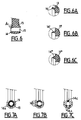
- the lips or rings made of material with the end of the lever can have different shapes in cross section.
- the lip or ring is inclined and has a frustoconical shape.
- the rings or lips 14 ′ formed integrally with the part 13 ′ have a triangular section giving great flexibility to this ring or lip.
- the ring or lip 14 ⁇ formed integrally with the end part 13 ⁇ of the lever has a tapered end part ensuring great flexibility.
- the lips 14 can constitute rings 14a continuous over the entire circumference surrounding the bore 15 (FIG. 7A), two discontinuous parts 14b along this circumference (FIG. 7B) or even several studs 14c (for example three) as shown in FIG. 7C.
- the gear lever also includes a ball joint 16 ensuring the support, the maintenance and the guiding of the lever 10, inside a fixed and guiding assembly 17 fixed on the vehicle floor.
- the ball joint 16 can be constituted by a ribbed assembly made of the same material as the rod 11 of the gear lever 10 or even by the juxtaposition of two plastic materials, in a bi-injection operation, as will be explained below.
- the shift lever is molded in a single operation.
- lever 20 which comprises a rod 21 whose cross section is cruciform and which has the desired qualities of rigidity and resistance.
- This rod 21 has, at one of its ends, a part 22 allowing the assembly of a ball or a maneuvering knob.
- This part 22 may have a cruciform profiled shape in cross section and a shape intended to allow molding and the attachment of the knob in longitudinal section, as can be seen in FIGS. 9 and 10.
- the part 22 of the rod 21 is made of the same plastic material as the rod 21, that is to say for example a polyamide thermoplastic material loaded with glass fibers.
- the operating knob 24 is made of a material such as polyvinyl chloride. This knob has an external shape ensuring, at the same time as the choice of plastic used for its production, a pleasant and comfortable manual contact for the driver.
- the operating ball can be attached to the part 22 of the rod by overmolding or even be produced by bi-injection.
- the knob is produced in a single molding operation with the entire gear lever.
- FIG. 11 there is shown an assembly part 25 comprising tongues 26 for assembly by clipping and a flange 27 which can be engaged on the end part 22 of the lever 20, for its attachment to the end of the the sink.
- the operating knob 28 is produced by molding, independently of the lever and has a hollow internal part allowing it to be assembled by clipping on the tongues 26.
- the pommel is fixed by placing the part 25 at the end of the lever 20 and then by force engagement of the pommel 28 on the fixing part by clipping the part 25.
- the gear lever 20 may comprise, in addition to the elements already described for the gear lever shown in FIG. 4, various elements for decorative or functional purposes. These elements can be produced by overmolding or by bi-injection molding.
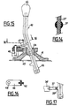
- the gear lever 20 shown in FIG. 8 has two parts 29 projecting radially outwards allowing the retaining of the protective sheath 30 made of rubber which is fixed around the gear lever, above the floor of the vehicle and which in particular protects the holding and guiding ball joint 31.
- the ball 31 can be made in the same way as the ball of the lever shown in Figure 4 or include, as shown in Figure 14, an internal part 21 'made of the same plastic as the rod 21 and a part external 31 ′ constituting the actual ball joint produced by overmolding or bi-injection molding on the body of the rod 21 ′.
- the external part 31 ′ of the ball joint can advantageously be made of a plastic material such as polyacetal which has a low coefficient of friction and a very good resistance to wear.
- the entire ball joint is produced with the rod of the lever during a single injection molding operation.
- the lower part 33 of the gear lever 20 ensuring the assembly of this lever to the wheelhouse of the gearbox is made, as before, in a single piece with the rod of the lever and in a single operation.
- This part 33 comprises, as before, lips or lateral rings 34 ensuring backlash during assembly of part 33 of the lever with the linkage linkage of the gearbox linkage.
- the gear lever shown in FIG. 8 also includes a part 35 projecting radially from one side of the gear lever which constitutes a push button for actuating an electrical relay or contactor 36 fixed on the vehicle, near the lever. speeds.
- the electrical contactor 36 is connected to a control servo which makes it possible, for example, to ensure that the selection of a speed, at a certain time, does indeed correspond to optimal conditions with respect to the engine speed.
- the projecting part 35 ′ of the gear lever may include an opening allowing the fixing of an articulation axis of a link rod 37 articulated, at its other end, on a movable part of the electrical contactor 36 ′.
- FIGS. 15 and 16 an alternative embodiment of a gear lever 40 according to the invention is seen, comprising, at one of its ends, an operating ball 42, at its other end, an assembly part 43 to the wheelhouse of the gearbox and, in an intermediate position between its ends, a sphere 44 for holding and guiding the rotation of the lever on a support 41 secured to the floor 45 of the vehicle.
- the gear lever further comprises a plate 46 made integrally with the rod of the lever during its injection molding and which can be reinforced by an internal metal frame 47.
- the plate 46 allows for anti-theft locking of the vehicle gear lever.
- the brochure 46 has a hole 48 at its end opposite the rod of the gear lever 40.
- the movement of the bar 49 between its locking and unlocking positions can be controlled by an electromagnet or by a mechanical system.
- the main advantages of the gear lever according to the invention are that it can be obtained, in one-piece form, in a single operation of molding a plastic material and that it can comprise numerous elements intended to perform various functions of control or safety related to the use of the gear lever.
- the gear lever being produced in a single operation of molding a plastic material, the production rates can be considerably increased and the cost price of the gear lever is very much lower than the cost price of the gear levers. of classic manufacture. We can envisage a reduction in the cost price of the gear lever of around 60%. It is also possible to envisage a considerable reduction in the costs of the investments necessary for the industrial production of the gear levers.
- the total mass of the lever is very much lower than that of a lever according to the prior art, the reduction in mass possibly being of the order of 50%.
- This weight gain has a significant influence on the transmission of mechanical noise towards the interior of the passenger compartment; a significant improvement in comfort is therefore obtained for the occupants of the vehicle.
- a bi-injection molding that is to say by injection of two different plastics in the mold for making the lever.
- a plastic material such as polyvinyl chloride is chosen to make the knob, in order to obtain the desired qualities with regard to the comfort of manual contact for the driver.
- the guiding and holding ball joint can be made with any structure and made of one or more plastic materials.
- the end part of the rod intended to be joined to the pommel can have any shape and the pommel can be attached to this end or formed during molding.
- the opposite end of the lever ensuring the connection with the wheelhouse of the gearbox can also have a shape different from that which has been described and which depends on the embodiment of the linkage part of the wheelhouse.
- the invention applies to the gear lever of any motor vehicle disposed in the passenger compartment of the vehicle. It concerns both a manual gearbox control lever and an automatic gearbox selection lever.
Landscapes
- Engineering & Computer Science (AREA)
- General Engineering & Computer Science (AREA)
- Mechanical Engineering (AREA)
- Chemical & Material Sciences (AREA)
- Combustion & Propulsion (AREA)
- Transportation (AREA)
- Arrangement Or Mounting Of Control Devices For Change-Speed Gearing (AREA)
- Mechanical Control Devices (AREA)
Claims (21)
Applications Claiming Priority (2)
| Application Number | Priority Date | Filing Date | Title |
|---|---|---|---|
| FR8907554 | 1989-06-07 | ||
| FR8907554A FR2648206B1 (fr) | 1989-06-07 | 1989-06-07 | Levier de commande de la boite de vitesses d'un vehicule automobile et procede de fabrication de ce levier |
Publications (2)
| Publication Number | Publication Date |
|---|---|
| EP0404613A1 EP0404613A1 (de) | 1990-12-27 |
| EP0404613B1 true EP0404613B1 (de) | 1992-08-12 |
Family
ID=9382483
Family Applications (1)
| Application Number | Title | Priority Date | Filing Date |
|---|---|---|---|
| EP19900401422 Expired - Lifetime EP0404613B1 (de) | 1989-06-07 | 1990-05-29 | Schalthebel für Schaltgetriebe eines Kraftfahrzeuges und Verfahren zu dessen Herstellung |
Country Status (4)
| Country | Link |
|---|---|
| EP (1) | EP0404613B1 (de) |
| DE (1) | DE69000254T2 (de) |
| ES (1) | ES2034834T3 (de) |
| FR (1) | FR2648206B1 (de) |
Families Citing this family (10)
| Publication number | Priority date | Publication date | Assignee | Title |
|---|---|---|---|---|
| CH685809A5 (de) * | 1992-08-14 | 1995-10-13 | Christian Roux | Handgriff. |
| FR2725166A1 (fr) * | 1994-09-30 | 1996-04-05 | Systeco Sa | Dispositif de fixation d'un pommeau de levier de commande de boite de vitesses pour vehicules automobiles |
| FR2725165A1 (fr) * | 1994-09-30 | 1996-04-05 | Systeco Sa | Pied de levier de commande de boite de vitesses pour vehicules automobiles |
| FR2727535B1 (fr) * | 1994-11-25 | 1997-04-11 | Horlogerie App Precision Ste | Levier de commande de boite de vitesses et son procede de fabrication |
| FR2739063B1 (fr) * | 1995-09-21 | 1998-05-22 | Peugeot | Levier de commande d'une boite de vitesses de vehicule automobile |
| FR2756227B1 (fr) * | 1996-11-22 | 1998-12-31 | Peugeot | Levier de manoeuvre muni d'un dispositif filtrant, et procede de fabrication d'un tel levier |
| FR2758770B1 (fr) * | 1997-01-24 | 1999-03-26 | Adwest Oci Sa | Ensemble levier et support pour la commande d'une boite de vitesses de vehicules automobiles |
| WO2017005288A1 (en) * | 2015-07-06 | 2017-01-12 | Kongsberg Automotive Ab | Gearshift assembly |
| FR3046747B1 (fr) * | 2016-01-14 | 2019-04-19 | Psa Automobiles Sa. | Element de reception de sollicitations mecaniques pour systeme de commande de changement de rapport de vitesses d’engin a moteur |
| KR101806711B1 (ko) * | 2016-06-15 | 2017-12-07 | 현대자동차주식회사 | 수동변속기의 변속레버 어셈블리 |
Family Cites Families (3)
| Publication number | Priority date | Publication date | Assignee | Title |
|---|---|---|---|---|
| DE2213361A1 (de) * | 1970-12-23 | 1973-09-27 | Wilhelm Neuscheler | Schalthebel fuer das getriebe von kraftwagen |
| DE2063371A1 (de) * | 1970-12-23 | 1972-07-13 | Wilhelm Neuscheler | Schalthebel fuer das getriebe von kraftwagen |
| IT1145601B (it) * | 1981-12-21 | 1986-11-05 | Lear Snc Di Foggini E C | Leva di comando particolarmente per carri di velocita di autoveicoli e sua procedimento di fabbricazione |
-
1989
- 1989-06-07 FR FR8907554A patent/FR2648206B1/fr not_active Expired - Lifetime
-
1990
- 1990-05-29 EP EP19900401422 patent/EP0404613B1/de not_active Expired - Lifetime
- 1990-05-29 DE DE1990600254 patent/DE69000254T2/de not_active Expired - Fee Related
- 1990-05-29 ES ES90401422T patent/ES2034834T3/es not_active Expired - Lifetime
Also Published As
| Publication number | Publication date |
|---|---|
| DE69000254D1 (de) | 1992-09-17 |
| DE69000254T2 (de) | 1993-01-07 |
| ES2034834T3 (es) | 1993-04-01 |
| EP0404613A1 (de) | 1990-12-27 |
| FR2648206B1 (fr) | 1991-09-27 |
| FR2648206A1 (fr) | 1990-12-14 |
Similar Documents
| Publication | Publication Date | Title |
|---|---|---|
| EP0404613B1 (de) | Schalthebel für Schaltgetriebe eines Kraftfahrzeuges und Verfahren zu dessen Herstellung | |
| FR2495077A1 (fr) | Installation d'essuie-glace pour vehicules automobiles | |
| FR2911896A1 (fr) | Poignee a verrouillage electrique pour element de fermeture mobile | |
| FR2543495A1 (fr) | Mecanisme de changement de vitesse a commande manuelle | |
| FR2491231A1 (fr) | Volant de direction comprenant un noyau en resine | |
| FR2809877A1 (fr) | Dispositif de traversee etanche d'un faisceau electrique par une ouverture de passage a travers un tablier d'un vehicule automobile et procede de montage du faisceau dans l'ouverture | |
| FR2487773A1 (fr) | Selecteur de rapports de transmission pour un dispositif de changement de vitesse de bicyclettes | |
| FR2785577A1 (fr) | Levier de changement de vitesse escamotable | |
| FR2614710A1 (fr) | Dispositif de manoeuvre comportant un segment de couronne dentee notamment pour la climatisation de voitures de tourisme | |
| EP0111204B1 (de) | Kupplungsausrücklager mit Geräusch- und Schwingungsdämpfung | |
| EP0983925B1 (de) | Kraftfahrzeug-Lenkeinrichtung mit einem im Lenkradzentrum fest angeordneten Steuerblock | |
| EP0704333A1 (de) | Schalthebel für Kraftfahrzeugschaltgetriebe | |
| EP0844127B1 (de) | Betätigungshebel mit einer Dämpfungsvorrichtung und Verfahren zur Herstellung von einem solchen Hebel | |
| FR2926644A1 (fr) | Poignee de commande pour articulation de siege de vehicule automobile | |
| EP0800132B1 (de) | Bekleidung eines Bedienungshebels in einem Fahrzeug | |
| EP0285508B1 (de) | Handbetätigte Steuervorrichtung eines mechanischen Getriebes | |
| EP0084472B1 (de) | Verstelleinrichtung für Schaltgetriebe | |
| EP2006555A1 (de) | Welle zur Übertragung von Bewegungen und/oder Drehkräften | |
| FR2590338A1 (fr) | Raccordement de commande a distance par cable | |
| FR2652924A1 (fr) | Dispositif de rappel elastique notamment d'un doigt de commande de changement de vitesses dans une boite de vitesses d'un vehicule automobile. | |
| EP0704643B1 (de) | Umlenkelement für den Gangwechselmechanismus in einem Kraftfahrzeugschaltgetriebe | |
| FR2739063A1 (fr) | Levier de commande d'une boite de vitesses de vehicule automobile | |
| EP4491912A1 (de) | Parksperren-entriegelungsvorrichtung für ein automatisches getriebe | |
| FR2665272A3 (fr) | Levier de changement de vitesse pour vehicules automobiles. | |
| FR2554055A1 (fr) | Roulette de meuble |
Legal Events
| Date | Code | Title | Description |
|---|---|---|---|
| PUAI | Public reference made under article 153(3) epc to a published international application that has entered the european phase |
Free format text: ORIGINAL CODE: 0009012 |
|
| AK | Designated contracting states |
Kind code of ref document: A1 Designated state(s): DE ES GB IT |
|
| 17P | Request for examination filed |
Effective date: 19901122 |
|
| 17Q | First examination report despatched |
Effective date: 19920121 |
|
| ITF | It: translation for a ep patent filed | ||
| GRAA | (expected) grant |
Free format text: ORIGINAL CODE: 0009210 |
|
| AK | Designated contracting states |
Kind code of ref document: B1 Designated state(s): DE ES GB IT |
|
| REF | Corresponds to: |
Ref document number: 69000254 Country of ref document: DE Date of ref document: 19920917 |
|
| GBT | Gb: translation of ep patent filed (gb section 77(6)(a)/1977) | ||
| REG | Reference to a national code |
Ref country code: ES Ref legal event code: FG2A Ref document number: 2034834 Country of ref document: ES Kind code of ref document: T3 |
|
| PLBE | No opposition filed within time limit |
Free format text: ORIGINAL CODE: 0009261 |
|
| STAA | Information on the status of an ep patent application or granted ep patent |
Free format text: STATUS: NO OPPOSITION FILED WITHIN TIME LIMIT |
|
| 26N | No opposition filed | ||
| REG | Reference to a national code |
Ref country code: GB Ref legal event code: IF02 |
|
| PGFP | Annual fee paid to national office [announced via postgrant information from national office to epo] |
Ref country code: DE Payment date: 20060505 Year of fee payment: 17 |
|
| REG | Reference to a national code |
Ref country code: GB Ref legal event code: 746 Effective date: 20070112 |
|
| PG25 | Lapsed in a contracting state [announced via postgrant information from national office to epo] |
Ref country code: DE Free format text: LAPSE BECAUSE OF NON-PAYMENT OF DUE FEES Effective date: 20071201 |
|
| PGFP | Annual fee paid to national office [announced via postgrant information from national office to epo] |
Ref country code: ES Payment date: 20080508 Year of fee payment: 19 |
|
| PGFP | Annual fee paid to national office [announced via postgrant information from national office to epo] |
Ref country code: IT Payment date: 20080520 Year of fee payment: 19 |
|
| PGFP | Annual fee paid to national office [announced via postgrant information from national office to epo] |
Ref country code: GB Payment date: 20080424 Year of fee payment: 19 |
|
| GBPC | Gb: european patent ceased through non-payment of renewal fee |
Effective date: 20090529 |
|
| PG25 | Lapsed in a contracting state [announced via postgrant information from national office to epo] |
Ref country code: GB Free format text: LAPSE BECAUSE OF NON-PAYMENT OF DUE FEES Effective date: 20090529 |
|
| REG | Reference to a national code |
Ref country code: ES Ref legal event code: FD2A Effective date: 20090530 |
|
| PG25 | Lapsed in a contracting state [announced via postgrant information from national office to epo] |
Ref country code: ES Free format text: LAPSE BECAUSE OF NON-PAYMENT OF DUE FEES Effective date: 20090530 |
|
| PG25 | Lapsed in a contracting state [announced via postgrant information from national office to epo] |
Ref country code: IT Free format text: LAPSE BECAUSE OF NON-PAYMENT OF DUE FEES Effective date: 20090529 |