EP0404598A2 - Interpolator - Google Patents
Interpolator Download PDFInfo
- Publication number
- EP0404598A2 EP0404598A2 EP90306870A EP90306870A EP0404598A2 EP 0404598 A2 EP0404598 A2 EP 0404598A2 EP 90306870 A EP90306870 A EP 90306870A EP 90306870 A EP90306870 A EP 90306870A EP 0404598 A2 EP0404598 A2 EP 0404598A2
- Authority
- EP
- European Patent Office
- Prior art keywords
- signals
- interpolator
- quadrature
- frequency
- input signals
- Prior art date
- Legal status (The legal status is an assumption and is not a legal conclusion. Google has not performed a legal analysis and makes no representation as to the accuracy of the status listed.)
- Withdrawn
Links
Images

Classifications
-
- G—PHYSICS
- G01—MEASURING; TESTING
- G01D—MEASURING NOT SPECIALLY ADAPTED FOR A SPECIFIC VARIABLE; ARRANGEMENTS FOR MEASURING TWO OR MORE VARIABLES NOT COVERED IN A SINGLE OTHER SUBCLASS; TARIFF METERING APPARATUS; MEASURING OR TESTING NOT OTHERWISE PROVIDED FOR
- G01D5/00—Mechanical means for transferring the output of a sensing member; Means for converting the output of a sensing member to another variable where the form or nature of the sensing member does not constrain the means for converting; Transducers not specially adapted for a specific variable
- G01D5/12—Mechanical means for transferring the output of a sensing member; Means for converting the output of a sensing member to another variable where the form or nature of the sensing member does not constrain the means for converting; Transducers not specially adapted for a specific variable using electric or magnetic means
- G01D5/244—Mechanical means for transferring the output of a sensing member; Means for converting the output of a sensing member to another variable where the form or nature of the sensing member does not constrain the means for converting; Transducers not specially adapted for a specific variable using electric or magnetic means influencing characteristics of pulses or pulse trains; generating pulses or pulse trains
- G01D5/24404—Interpolation using high frequency signals
Definitions
- This invention relates to interpolators and to metrological apparatus including an interpolator.
- a surface sensor traverses the surface of a workpiece for measuring surface characteristics, for example roughness or form
- means may be provided for detecting relative movement between the workpiece support and the surface sensor whereby the output of the surface sensor may be sampled at regularly spaced points on the surface thus to provide information from which the required surface characteristics can be derived.
- Various forms of movement detector are known which produce quadrature signals which may be used to sample the surface sensor output, for example, at the zero crossing points of the quadrature signals.
- An example of such a movement detector is an optical grating and associated transducer arrangement which, in response to detection of light reflected from the grating, produces the quadrature signals.
- a problem with such detectors is that the frequency of the quadrature signals may not be high enough to provide the required resolution. It is known to increase the resolution by interpolation.
- Known interpolators comprise a bank of comparators to which the quadrature signals are supplied in various proportions and which output a series of sine waves having different phases from each other.
- a problem with such interpolators is that the circuit design is relatively complex and they suffer from problems of noise.
- the circuit is made complex by the need to provide four inputs to the amplifier which generates cos2A, and by the additional circuitry which is needed to generate the signals 2sinA and -sinA which are required by the multiplier inputs.
- the present invention provides an improved interpolator for receiving input quadrature signals and arranged to perform a mathematical operation thereon to provide output signals at double or quadruple or other multiples of the input frequency, the output signals being in quadrature, the interpolator comprising means which squares one of the input quadrature signals but not the other.
- the DC component represented by the term "1/2" can be removed by a filter, to leave -(cos2A)/2 or +(cos2A)/2.
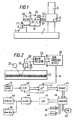
- a metrological instrument for measuring surface texture or form comprises a base 2 for supporting a workpiece 4 having a surface 6 whose texture is to be measured.
- a vertical column 8 secured to the base 2 supports a vertically movable carriage 10 on which a horizontal datum bar 12 is mounted.
- a further carriage 14 is mounted for horizontal movement along the bar 12 and carries a transducer 16 having a stylus arm 18 which carries a stylus 19.
- a motor 20 indicated diagrammatically in Fig. 1 is provided on the carriage 14 for effecting horizontal movement thereof along the datum bar 12 and a further motor 21 is provided on carriage 10 for effecting vertical movement thereof up and down the column 8.
- the carriage 10 In operation of the apparatus, the carriage 10 is arranged at a vertical position such that the stylus 19 engages the surface 6. Thereafter, the motor 20 is operated to cause the carriage 14 to move horizontally along the datum bar 12 thus causing the stylus 19 to traverse the surface 6 to be measured.
- a linear optical grating shown schematically at 22 in figure 1, comprising a series of reflective and non-reflective bands, is fixed with respect to the datum bar 12 and light from a light source 24 is reflected from the grating 22 and detected by a pair of light sensors 26, 27 mounted on the carriage 14.
- the grating may be formed of a series of transmissive and non-transmissive bands, with the sensors 26, 27 arranged to detect light transmitted through the grating.
- a reference scale (not shown) may be provided associated with the sensors 26, 27. As the carriage moves along the datum bar 12, the sensors 26, 27 provide sinusoidal electrical signals on lines 28 and 30 respectively. The sensors 26 and 27 are positioned so that the signals on lines 28 and 30 are in quadrature.
- interpolator 32 which causes their frequencies to be quadrupled.
- the interpolator 32 outputs the resulting signals on line 34 and 36 and supplies them to a zero crossing detector 38 which outputs pulses on line 39 in response to each zero crossing point in each of the signals on lines 34 and 36.
- the signals from sensors 26, 27 have a period corresponding to 4 microns.
- a pulse then appears on line 39 for each 0.25 microns of movement of the carriage 14 along datum bar 12.
- Transducer 16 is preferably an inductive transducer and, in response to this substantially vertical movement, produces an output signal which is digitised by an analogue-to- digital converter 40 and supplied to a microprocessor 42 which, in response to the pulses on lines 39, samples the digitised signal from transducer 16 at 0.25 micron intervals of movement of the carriage 14 along the datum bar 12 and stores the resulting samples in a memory 44.
- the analogue-to-digital converter 40 and the processing performed on the signal output there from by the microprocessor 42 may be as described in application filed concurrently herewith with agent's reference 3017430 and claiming priority from UK patent applications 8914418.2 and 8914419.0.
- the concurrently filed application is incorporated herein by reference.
- the apparatus includes a computer 46 which is programmed to effect a general overall control of the apparatus, including control of the motors 20 and 21, and to process the signals stored in memory 44 to provide information as to the surface texture and form of the surface 6.
- a keyboard 45 is provided for inputting instructions to the computer 46.
- Signals representing the surface characteristics are output by computer 46, via a low pass filter 48 whose purpose will be further explained below, to a display device 49, such as a cathode ray tube, and a printer 50 which may be operable to produce a trace of the surface of the workpiece.
- the display device 49 and the printer 50 may use digital input signals. Alternatively, either or both of them may use analogue input signals, in which case the signals are passed through a digital-to-analogue converter 47 as shown in Figure 2.
- the digital to analogue converter 47 may be placed before or after the filter 48, which will be an analogue or digital filter accordingly.
- the interpolator 32 comprises a first channel 52 which receives the signal on line 28 and a second channel 54 which receives the signal on line 30.
- the channels comprise filters 56a, 56b, automatic gain control circuits 58a, 58b multipliers 60a, 60b, all forming a first stage.
- a second stage 64 comprises filters 66a, 66b, amplifiers 68a, 68b, multipliers 70a, 70b and filters 72a, 72b.
- the signals on lines 28 and 30 are sinusoidal and in quadrature. However, each signal will in practice contain a DC offset component which will drift, as the optical sensors 26, 27 traverse the grating 22, due to variations in the reflectance of the grating along its length. Also, due to errors in the grating, the signals on lines 28 and 30 will generally not be in perfect quadrature but will contain a varying phase error. Thus, if the signals on lines 28 and 30 are respectively V1 and V2, they may be represented as follows: where V1 , and V2 , are the DC mean and AC amplitude voltages respectively of the two signals, x is the traverse displacement, ⁇ is the grating wavelength and ⁇ is the phase error from quadrature.
- Filters 56a and 56b are high pass filters and remove the DC drift components V1 and V2 from these signals.
- Automatic gain control circuits 58a and 58b eliminate any fluctuations in the amplitude of the two signals arising from errors in the grating.
- Multiplier 60b multiplies processed signals as output by the automatic gain control circuits to produce a signal V3: which can be expressed as:
- Sin(- ⁇ ) is removed by filter 66b to leave a sine signal at twice the input frequency.
- Multiplier 60a multiplies the processed signal as output by automatic gain control circuit 58a, by itself to provide a signal V4:
- Amplifiers 68a and 68b compensate for loss of gain in the preceding circuits.
- Multipliers 70a, 70b and filters 72a and 72b act in the same manner as multipliers 60a, 60b and filters 66a and 66b as described above, and thus filters 72a and 72b provide on lines 34 and 36 quadrature output signals at four times the input frequency with a small varying phase error ⁇ as apparent from the right hand term of Equation 4.
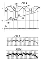
- phase error is illustrated in Fig. 4 in which waveform A illustrates the quadrature waves, with phase error ⁇ , output by the interpolator 32.
- Waveform B drawn on the assumption that the surface 6 being sensed is at an angle ⁇ to the horizontal illustrates, in the solid line curve 80, the values of the signal from transducer 16 which would be output by microprocessor 42 in the absence of any phase error ⁇ .
- zero crossing points, 82, 84, 86 etc arise slightly early so that values of the signal from transducer 16 slightly lower than the correct values are obtained by microprocessor 42, as indicated at 82a, 84a and 86a in Fig. 4. This gives rise to a noise signal, which is illustrated in curve C of Fig.
- Filter 48 is a low pass filter which is provided to filter out the noise component C.
- the effect of filter 48 can be appreciated by consideration of Figs. 5 and 6 in which Fig. 5 shows a trace obtained with the filter 48 present and Fig. 6 shows a trace obtained with the filter 48 absent.
- the action of the filter may alternatively be provided by the microprocessor 42 and conventional digital filtering techniques.
- traces are reproductions of traces obtained in an experimental apparatus utilising a grating with a pitch of 8 microns, an interpolator 32 which produces quadrature output signals at four times the input frequency, the carriage 14 operating at a speed of 0.5mm/s and the filter 48 or equivalent filtering out frequencies above 300Hz, corresponding to surface wavelengths below 17 ⁇ m
- the quadrative noise would be at a frequency of about 1kHz
- the DC offset noise would be at a frequency of about 500Hz, both of which would be filtered out.
- interpolator 32 in accordance with the invention results in interpolation noise components which are at a higher frequency than the frequency of the signals representing the surface characteristics of interest and accordingly such noise components are easily filtered out to provide a high resolution, clean trace as shown in Fig. 5 rather than the noisy trace of Fig. 6.
- each channel of the interpolator includes three filters, it would be possible to modify the arrangement to eliminate one or two of these filters, for example, while still achieving useful effects.
- the invention is particularly advantageous when used in combination with an optical grating since it makes it possible to obtain a substantially higher resolution than could otherwise be achieved economically with optical gratings and since the effects of varying drift and phase errors associated with such gratings are easily eliminated.
- other apparatus for example interferometers, or rotary encoders.
- the invention can be applied to apparatus other than surface texture or form measuring apparatus.
- apparatus other than surface texture or form measuring apparatus.
- it could be applied in a coordinate measuring machine or in a machine tool particularly where it is required to resolve a signal of a given wavelength into finer intervals.
- interpolator is implemented with analogue circuitry, it could alternatively be implemented digitally.
Landscapes
- Physics & Mathematics (AREA)
- General Physics & Mathematics (AREA)
- Optical Transform (AREA)
- Length Measuring Devices By Optical Means (AREA)
- Length Measuring Devices With Unspecified Measuring Means (AREA)
- Transmission And Conversion Of Sensor Element Output (AREA)
Applications Claiming Priority (2)
| Application Number | Priority Date | Filing Date | Title |
|---|---|---|---|
| GB898914417A GB8914417D0 (en) | 1989-06-23 | 1989-06-23 | Interpolator |
| GB8914417 | 1989-06-23 |
Publications (2)
| Publication Number | Publication Date |
|---|---|
| EP0404598A2 true EP0404598A2 (de) | 1990-12-27 |
| EP0404598A3 EP0404598A3 (de) | 1991-09-11 |
Family
ID=10658924
Family Applications (1)
| Application Number | Title | Priority Date | Filing Date |
|---|---|---|---|
| EP19900306870 Withdrawn EP0404598A3 (de) | 1989-06-23 | 1990-06-22 | Interpolator |
Country Status (5)
| Country | Link |
|---|---|
| US (1) | US5063291A (de) |
| EP (1) | EP0404598A3 (de) |
| JP (1) | JPH03128417A (de) |
| CN (1) | CN1022508C (de) |
| GB (2) | GB8914417D0 (de) |
Families Citing this family (50)
| Publication number | Priority date | Publication date | Assignee | Title |
|---|---|---|---|---|
| DE69028158T2 (de) * | 1989-06-23 | 1997-02-20 | Rank Taylor Hobson Ltd | Messtechnische Vorrichtung und Kalibrierverfahren dafür |
| CH683798A5 (fr) * | 1990-12-10 | 1994-05-13 | Tesa Sa | Capteur de position pour un appareil de mesure de grandeurs linéaires ou angulaires. |
| US5211539A (en) * | 1991-05-13 | 1993-05-18 | Allied-Signal Inc. | Apparatus for indicating the pitch of turbofan blades |
| GB2256476B (en) * | 1991-05-30 | 1995-09-27 | Rank Taylor Hobson Ltd | Positional measurement |
| US5949695A (en) * | 1997-01-10 | 1999-09-07 | Harris Corporation | Interpolator using a plurality of polynomial equations and associated methods |
| DE10001800C2 (de) * | 2000-01-18 | 2002-07-18 | Om Engineering Gmbh | Verfahren und Vorrichtung zur Messung insbesondere von Oberflächentopologien in mikroskopischer Auflösung |
| US20020110200A1 (en) * | 2000-12-19 | 2002-08-15 | Intel Corporation | Method for quadrature phase decoding allowing for skipped states |
| EP2140891B1 (de) | 2001-05-18 | 2013-03-27 | DEKA Products Limited Partnership | Leitung zum Anschluss an eine Flüssigkeitszufuhrvorrichtung |
| US8034026B2 (en) | 2001-05-18 | 2011-10-11 | Deka Products Limited Partnership | Infusion pump assembly |
| US20040262502A1 (en) * | 2003-06-26 | 2004-12-30 | Xerox Corporation | Position encoder |
| US6972403B2 (en) * | 2003-06-26 | 2005-12-06 | Xerox Corporation | Position encoder |
| DE602006009202D1 (de) * | 2005-11-08 | 2009-10-29 | Mitutoyo Corp | Formmessgerät |
| US7262714B2 (en) | 2005-12-01 | 2007-08-28 | Avago Technologies General Ip (Singapore) Pte. Ltd. | Interpolating encoder utilizing a frequency multiplier |
| US11478623B2 (en) | 2006-02-09 | 2022-10-25 | Deka Products Limited Partnership | Infusion pump assembly |
| US11318249B2 (en) | 2006-02-09 | 2022-05-03 | Deka Products Limited Partnership | Infusion pump assembly |
| US12274857B2 (en) | 2006-02-09 | 2025-04-15 | Deka Products Limited Partnership | Method and system for shape-memory alloy wire control |
| US11497846B2 (en) | 2006-02-09 | 2022-11-15 | Deka Products Limited Partnership | Patch-sized fluid delivery systems and methods |
| US12151080B2 (en) | 2006-02-09 | 2024-11-26 | Deka Products Limited Partnership | Adhesive and peripheral systems and methods for medical devices |
| US11027058B2 (en) | 2006-02-09 | 2021-06-08 | Deka Products Limited Partnership | Infusion pump assembly |
| US12070574B2 (en) | 2006-02-09 | 2024-08-27 | Deka Products Limited Partnership | Apparatus, systems and methods for an infusion pump assembly |
| US11364335B2 (en) | 2006-02-09 | 2022-06-21 | Deka Products Limited Partnership | Apparatus, system and method for fluid delivery |
| CN103736165B (zh) | 2006-02-09 | 2017-05-10 | 德卡产品有限公司 | 流体分配器件、流体流的测量方法和系统及流体输送系统 |
| JP2010517700A (ja) | 2007-02-09 | 2010-05-27 | デカ・プロダクツ・リミテッド・パートナーシップ | 自動挿入アセンブリ |
| AU2008347241B2 (en) | 2007-12-31 | 2014-09-18 | Deka Products Limited Partnership | Infusion pump assembly |
| US10188787B2 (en) | 2007-12-31 | 2019-01-29 | Deka Products Limited Partnership | Apparatus, system and method for fluid delivery |
| US9456955B2 (en) | 2007-12-31 | 2016-10-04 | Deka Products Limited Partnership | Apparatus, system and method for fluid delivery |
| US8491570B2 (en) | 2007-12-31 | 2013-07-23 | Deka Products Limited Partnership | Infusion pump assembly |
| US12447265B2 (en) | 2007-12-31 | 2025-10-21 | Deka Products Limited Partnership | Apparatus, system and method for fluid delivery |
| US8900188B2 (en) | 2007-12-31 | 2014-12-02 | Deka Products Limited Partnership | Split ring resonator antenna adapted for use in wirelessly controlled medical device |
| US10080704B2 (en) | 2007-12-31 | 2018-09-25 | Deka Products Limited Partnership | Apparatus, system and method for fluid delivery |
| US8881774B2 (en) | 2007-12-31 | 2014-11-11 | Deka Research & Development Corp. | Apparatus, system and method for fluid delivery |
| CA3037726C (en) | 2008-09-15 | 2021-11-16 | Deka Products Limited Partnership | Systems and methods for fluid delivery |
| US8262616B2 (en) | 2008-10-10 | 2012-09-11 | Deka Products Limited Partnership | Infusion pump assembly |
| US8267892B2 (en) | 2008-10-10 | 2012-09-18 | Deka Products Limited Partnership | Multi-language / multi-processor infusion pump assembly |
| US8066672B2 (en) | 2008-10-10 | 2011-11-29 | Deka Products Limited Partnership | Infusion pump assembly with a backup power supply |
| US8223028B2 (en) | 2008-10-10 | 2012-07-17 | Deka Products Limited Partnership | Occlusion detection system and method |
| US12186531B2 (en) | 2008-10-10 | 2025-01-07 | Deka Products Limited Partnership | Infusion pump assembly |
| US12370327B2 (en) | 2008-10-10 | 2025-07-29 | Deka Products Limited Partnership | Infusion pump methods, systems and apparatus |
| US8016789B2 (en) | 2008-10-10 | 2011-09-13 | Deka Products Limited Partnership | Pump assembly with a removable cover assembly |
| US9180245B2 (en) | 2008-10-10 | 2015-11-10 | Deka Products Limited Partnership | System and method for administering an infusible fluid |
| US8708376B2 (en) | 2008-10-10 | 2014-04-29 | Deka Products Limited Partnership | Medium connector |
| US8035074B2 (en) * | 2009-02-09 | 2011-10-11 | Avago Technologies Ecbu Ip (Singapore) Pte. Ltd. | Automatic gain control for motion encoder signals |
| EP2453948B1 (de) | 2009-07-15 | 2015-02-18 | DEKA Products Limited Partnership | Vorrichtung, systeme und verfahren für eine infusionspumpenanordnung |
| CA3033439C (en) | 2010-01-22 | 2021-04-06 | Deka Products Limited Partnership | Method and system for shape-memory alloy wire control |
| US8384014B2 (en) * | 2010-10-27 | 2013-02-26 | Avago Technologies Ecbu Ip (Singapore) Pte. Ltd. | Interpolation method and device for increasing the resolution of encoders |
| WO2013134519A2 (en) | 2012-03-07 | 2013-09-12 | Deka Products Limited Partnership | Apparatus, system and method for fluid delivery |
| CA3130345A1 (en) | 2013-07-03 | 2015-01-08 | Deka Products Limited Partnership | Apparatus, system and method for fluid delivery |
| WO2015010669A1 (de) * | 2013-07-23 | 2015-01-29 | BALLUF GmbH | Verfahren zur dynamischen linearisierung von sensorsignalen eines magnetband-längenmesssystems |
| JP2017181876A (ja) * | 2016-03-31 | 2017-10-05 | キヤノン株式会社 | 防振装置およびそれを有するレンズ装置及び撮像装置 |
| WO2019209963A1 (en) | 2018-04-24 | 2019-10-31 | Deka Products Limited Partnership | Apparatus and system for fluid delivery |
Family Cites Families (9)
| Publication number | Priority date | Publication date | Assignee | Title |
|---|---|---|---|---|
| US3410976A (en) * | 1965-06-09 | 1968-11-12 | Itek Corp | Shaft angle encoder with phase detection |
| GB1363411A (en) * | 1970-07-01 | 1974-08-14 | Nat Res Dev | Position indicating or measuring devices |
| DD141866A1 (de) * | 1979-03-30 | 1980-05-21 | Wolfgang Seide | Verfahren und anordnung zur dynamischen messung von bewegungsgroessen |
| US4359688A (en) * | 1980-10-30 | 1982-11-16 | Bei Electronics, Inc. | Frequency multiplying circuit for an optical encoder |
| US4468617A (en) * | 1982-02-11 | 1984-08-28 | General Electric Company | Velocity sensor and method of producing a velocity signal |
| NL8303855A (nl) * | 1983-11-10 | 1985-06-03 | Philips Nv | Frequentieverdubbelschakeling. |
| JPS63503564A (ja) * | 1986-06-21 | 1988-12-22 | レニショウ パブリック リミテッド カンパニー | 補間装置 |
| EP0255977A3 (de) * | 1986-08-08 | 1990-03-28 | Renishaw plc | Verarbeitung von verschobenen Signalen |
| GB2195762A (en) * | 1986-10-03 | 1988-04-13 | Rank Taylor Hobson Ltd | Interpolator |
-
1989
- 1989-06-23 GB GB898914417A patent/GB8914417D0/en active Pending
-
1990
- 1990-06-22 JP JP2165509A patent/JPH03128417A/ja active Pending
- 1990-06-22 EP EP19900306870 patent/EP0404598A3/de not_active Withdrawn
- 1990-06-22 US US07/542,707 patent/US5063291A/en not_active Expired - Fee Related
- 1990-06-23 CN CN90106540.4A patent/CN1022508C/zh not_active Expired - Fee Related
- 1990-06-25 GB GB9014116A patent/GB2233521B/en not_active Expired - Lifetime
Also Published As
| Publication number | Publication date |
|---|---|
| EP0404598A3 (de) | 1991-09-11 |
| GB8914417D0 (en) | 1989-08-09 |
| CN1022508C (zh) | 1993-10-20 |
| US5063291A (en) | 1991-11-05 |
| GB2233521A (en) | 1991-01-09 |
| GB9014116D0 (en) | 1990-08-15 |
| JPH03128417A (ja) | 1991-05-31 |
| CN1048921A (zh) | 1991-01-30 |
| GB2233521B (en) | 1992-12-23 |
Similar Documents
| Publication | Publication Date | Title |
|---|---|---|
| US5063291A (en) | Optical grating with interpolator having multiplying means to produce quadrature signals | |
| US4595991A (en) | Position measuring method and apparatus | |
| US5204734A (en) | Rough surface profiler and method | |
| EP0404597B1 (de) | Messtechnische Vorrichtung und Kalibrierverfahren dafür | |
| EP0455983A1 (de) | Positionsmesseinrichtung mit Phaseneinstellungsschaltung und Verfahren zur Phasenanpassung | |
| JPH0428005Y2 (de) | ||
| EP0668989B1 (de) | Metrologisches instrument | |
| JPH0658779A (ja) | 測定装置 | |
| GB1575054A (en) | Method of and apparatus for laser-beam processing of a workpiece | |
| US4792739A (en) | High-accuracy position detection apparatus | |
| JPH049241B2 (de) | ||
| JPH08320260A (ja) | 調節可能な光路長差を有する干渉計装置 | |
| US7748251B2 (en) | Circuit configuration and method for ascertaining tilt errors in connection with a position-measuring device | |
| US6897961B2 (en) | Heterodyne lateral grating interferometric encoder | |
| US3953133A (en) | Method of determining the angular position of a workpiece and apparatus therefor | |
| JPH09113213A (ja) | 高調波信号成分を濾波する装置 | |
| US6580066B2 (en) | Measurement signal generating circuit for linear scale | |
| JP4914899B2 (ja) | 電気信号の振幅状態測定方法 | |
| JP5061049B2 (ja) | 微細形状測定装置 | |
| JP2897080B2 (ja) | 変位計調整方法及びその装置 | |
| JP2797585B2 (ja) | 走査型トンネリング分光装置 | |
| KR910009090B1 (ko) | 디지탈방식의 리졸버/디지탈변환장치 | |
| JP3030760B2 (ja) | 直流分除去回路 | |
| KR101420806B1 (ko) | 신호 처리 장치 | |
| JPH0361809A (ja) | デジタイザ |
Legal Events
| Date | Code | Title | Description |
|---|---|---|---|
| PUAI | Public reference made under article 153(3) epc to a published international application that has entered the european phase |
Free format text: ORIGINAL CODE: 0009012 |
|
| AK | Designated contracting states |
Kind code of ref document: A2 Designated state(s): CH DE DK GB IT LI SE |
|
| PUAL | Search report despatched |
Free format text: ORIGINAL CODE: 0009013 |
|
| AK | Designated contracting states |
Kind code of ref document: A3 Designated state(s): CH DE DK GB IT LI SE |
|
| 17P | Request for examination filed |
Effective date: 19920219 |
|
| 17Q | First examination report despatched |
Effective date: 19930407 |
|
| STAA | Information on the status of an ep patent application or granted ep patent |
Free format text: STATUS: THE APPLICATION IS DEEMED TO BE WITHDRAWN |
|
| 18D | Application deemed to be withdrawn |
Effective date: 19931030 |