EP0404571A1 - Sliding member - Google Patents
Sliding member Download PDFInfo
- Publication number
- EP0404571A1 EP0404571A1 EP90306795A EP90306795A EP0404571A1 EP 0404571 A1 EP0404571 A1 EP 0404571A1 EP 90306795 A EP90306795 A EP 90306795A EP 90306795 A EP90306795 A EP 90306795A EP 0404571 A1 EP0404571 A1 EP 0404571A1
- Authority
- EP
- European Patent Office
- Prior art keywords
- sliding member
- fiber
- member according
- inorganic
- powder
- Prior art date
- Legal status (The legal status is an assumption and is not a legal conclusion. Google has not performed a legal analysis and makes no representation as to the accuracy of the status listed.)
- Granted
Links
Images


Classifications
-
- C—CHEMISTRY; METALLURGY
- C04—CEMENTS; CONCRETE; ARTIFICIAL STONE; CERAMICS; REFRACTORIES
- C04B—LIME, MAGNESIA; SLAG; CEMENTS; COMPOSITIONS THEREOF, e.g. MORTARS, CONCRETE OR LIKE BUILDING MATERIALS; ARTIFICIAL STONE; CERAMICS; REFRACTORIES; TREATMENT OF NATURAL STONE
- C04B35/00—Shaped ceramic products characterised by their composition; Ceramics compositions; Processing powders of inorganic compounds preparatory to the manufacturing of ceramic products
- C04B35/71—Ceramic products containing macroscopic reinforcing agents
- C04B35/78—Ceramic products containing macroscopic reinforcing agents containing non-metallic materials
- C04B35/80—Fibres, filaments, whiskers, platelets, or the like
- C04B35/83—Carbon fibres in a carbon matrix
-
- F—MECHANICAL ENGINEERING; LIGHTING; HEATING; WEAPONS; BLASTING
- F16—ENGINEERING ELEMENTS AND UNITS; GENERAL MEASURES FOR PRODUCING AND MAINTAINING EFFECTIVE FUNCTIONING OF MACHINES OR INSTALLATIONS; THERMAL INSULATION IN GENERAL
- F16D—COUPLINGS FOR TRANSMITTING ROTATION; CLUTCHES; BRAKES
- F16D69/00—Friction linings; Attachment thereof; Selection of coacting friction substances or surfaces
- F16D69/02—Compositions of linings; Methods of manufacturing
- F16D69/023—Composite materials containing carbon and carbon fibres or fibres made of carbonizable material
Definitions
- the present invention relates to a sliding member having high strength and excellent heat resistance, abrasion resistance and oxidation resistance.
- the sliding member is suitable for making a brake shoe, a brake lining, a brake pad, a bush, a thrust washer, a piston ring, vanes, rotors and sleeves of pumps, a bearing for a high temperature application and the like for an aircraft, a racing car and so on.
- the sliding member of the present invention can be applied to both of a dry type friction member and a wet type friction member. Further, the sliding member of the present invention can be made into a sliding member having a low friction coefficient and excellent anti-seizure properties under a dry sliding condition and being applicable to a mechanical structural body, thereby contributing to reduce the frictional loss thereof.
- a sliding member used in a brake shoe component member the like for an aircraft, a racing car and so on especially requires heat resistance and abrasion resistance.
- the sliding portion is usually used under an oil lubrication condition.
- a sliding member used under a dry condition a sintered material impregnated with an oil, a copper sintered alloy and a carbon material have been well known.
- the carbon material the following carbon materials have been used, i.e., a carbon material made by burning and solidifying a carbonaceous powder and the other carbon material made by sintering a carbonaceous powder at a high temperature to graphitize the carbonaceous powder.
- this carbon fiber reinforced carbon has been provided for the above-mentioned applications, and is said to be a material improving the strength of the conventional carbon materials.
- this carbon fiber reinforced carbon is produced by impregnating a liquid carbonaceous material, such as tar, pitch and thermosetting resin, which works as a binder into carbon fiber which works as a reinforcement and which has been carbonized or graphitized and further subjected to a surface treatment like oxidation. Then, the resulting binder impregnated carbon fiber is burned in an inert gas atmosphere. If necessary, the resulting sintered product is graphitized thereafter.
- a liquid carbonaceous material such as tar, pitch and thermosetting resin
- the carbon fiber reinforced carbon thus produced uses the liquid carbonaceous material as the binder, volatile substances are generated by the decomposition of the liquid carbonaceous material during the burning, thereby forming pores. Accordingly, the boundary adhesion between the reinforcement and the binder deteriorates, and the density of the product decreases. Consequently, the product is inferior in the strength and the abrasion resistance.
- the pores of the product have been repeatedly filled with a liquid impregnant working as a binder, and the product has been repeatedly re-burned to decrease the porosity.
- the product thus obtained has been still porous.
- these complicated processes have resulted in the increasing manufacturing cost.
- the above-mentioned conventional carbon fiber reinforced carbon suffers from a low friction coefficient ( ⁇ ) especially under a low load.
- the above-mentioned conventional carbon fiber reinforced carbon has been known to be superior in the anti-seizure properties, it is seized at the load of 50 to 75 kgf/cm2 which is as much as 3 to 4 times that of steel for a structural application under a dry condition.
- the carbon fiber reinforced carbon since the carbon fiber reinforced carbon only exhibits the friction coefficient ( ⁇ ) of 0.2 to 0.5 under a dry condition, it is not a material of a low friction coefficient, nor a suitable material for a sliding portion of a mechanical structural body.
- the present invention has been developed in view of these problems, and it is therefore an object of the present invention to provide a sliding member having high strength and an excellent friction/abrasion property and being manufacturable at a low cost.
- a sliding member according to the present invention has a predetermined shape, and comprises a sintered body obtained by sintering a composite body comprising: preliminarily carbonized carbonaceous fiber; inorganic powder or inorganic fiber; and self-sintering carbonaceous powder with the preliminarily carbonized carbonaceous fiber and the inorganic powder or the inorganic fiber buried therein.
- a sliding member according to the present invention which is suitable for a sliding portion of a mechanical structural body has a predetermined shape, and comprises a sintered body obtained by sintering a composite body comprising: preliminarily carbonized carbonaceous fiber; boron compound powder; and self-sintering carbonaceous powder with the preliminarily carbonized carbonaceous fiber and the boron compound powder buried therein.
- the shape of the sliding member is not restricted particularly.
- the sliding member may be made into a predetermined shape of a brake shoe, a brake lining, a brake pad, a piston ring, a bearing and the like.
- the preliminarily carbonized carbonaceous fiber constitutes a reinforcement of the sliding member of the present invention.
- the raw material of the preliminarily carbonized carbonaceous fiber is not restricted particularly.
- the raw material may be PAN (polyacrylonitrile), rayon, or pitch and the like.
- the preliminarily carbonized carbonaceous fiber is a carbonaceous fiber which has not been subjected to an ordinary carbonizing treatment. In other words, it is a carbonaceous fiber which can accept further carbonizing when it is further subjected to a heat treatment.
- the preliminarily carbonized carbonaceous fiber may be spun fiber itself or infusible fiber obtained by making the spun fiber infusible at a temperature of less than 550 °C.
- polymer fiber such as PAN fiber
- the preliminarily carbonized carbonaceous fiber may be polymer fiber which has got through a decomposition process and is prior to a graphitizing treatment.
- spun pitch fiber obtained by spinning coal or petroleum raw pitch and infusible fiber obtained by making the spun pitch fiber infusible.
- the pitch fiber may be obtained in the following manner: The raw pitch is supplied in a spinning machine, heated at the temperature of about 300 to 400 °C, and extruded through a nozzle of the spinning machine by applying a pressure of an inert gas.
- the pitch fiber thus obtained may be made into the infusible pitch fiber by heating the pitch fiber at 150 to 500 °C for 0.5 to 5 hours in an oxidizing atmosphere.
- the raw pitch may be either optically isotropic or optically anisotropic.
- the fiber length of the preliminarily carbonized carbonaceous fiber either the short fiber or the long fiber thereof may be used.
- the fiber length thereof may be 0.01 to 50 mm, and particularly the short fiber having the length of 0.03 to 10 mm is preferred in view of the easy mixing and the aspect ratio.
- the fibers get entangled to deteriorate the dispersibility and finally the product isotropy, one of the important properties of the product.
- the strength of the product decreases sharply.
- the fiber diameter thereof 5 to 25 ⁇ m is preferred. Further, a non-woven fabric or a coating fabric made of these fibers may be used.
- the preliminarily carbonized carbonaceous fiber may be preferably subjected to a surface treatment using a viscous material such as tar, pitch and organic polymer in order to improve the affinity with a binder.
- This surface treatment may be carried out by stirring 100 parts by weight of the preliminarily carbonized carbonaceous fiber with 100 to 1000 parts by weight of the viscous material. The mixture is then washed with an organic solvent, and dried.
- the tar or pitch used for the surface treatment may be derived either from coal or petroleum.
- a heat treatment of about 140 to 170 °C is required during the stirring.
- the tar is accordingly more preferred for the viscous material.
- coal tar is much more preferred in view of the carbonization material loss in the subsequent carbonizing and graphitizing processes.
- the organic polymer used for the surface treatment may be phenol resin, polyvinyl chloride, polyvinyl alcohol and the like.
- the organic solvent used for the washing of the surface treatment may be an aromatic solvent such as toluene and xylene.
- the washing is carried out by stirring 100 parts by weight of the mixture of the preliminarily carbonized carbonaceous fiber and the viscous material with 100 to 1000 parts by weight of the organic solvent, thereby removing light oil components containing many volatile substances.
- the preliminarily carbonized carbonaceous fiber thus washed is dried by heating and/or depressurizing in a non-oxidizing atmosphere such as nitrogen and argon. The drying is not restricted to the above as far as the organic solvent employed for the washing can be removed.
- the preliminarily carbonized carbonaceous fiber thus surface-treated and dried is dispersed, if required, since the dried preliminarily carbonized carbonaceous fiber may sometimes come together in a mass or aggregate. If such is the case, the dispersion may be carried out by an ordinary means such as a powder mill, an atomizer, a pulverizer and the like.
- the inorganic powder or the inorganic fiber constitutes the reinforcement of the sliding member of the present invention together with the preliminarily carbonized carbonaceous fiber.
- the inorganic powder or the inorganic fiber is added in order to increase the friction coefficient ( ⁇ ) of the sliding member and make it stable, or in order to give the sliding member high abrasion resistance and high anti-seizure properties even when the sliding member has a friction coefficient ( ⁇ ) of a low value.
- the inorganic powder or the inorganic fiber may preferably be one having the melting point of 1000 °C or higher and being not reactable with carbon, and may more preferably be one having the hardness of 1000 Hv or more as well.
- inorganic oxide inorganic carbide, inorganic nitride, inorganic boride and the like may be used.
- the inorganic oxide may be Al2O3, TiO2, ZrO2, MgO and the like.
- the inorganic carbide may be B4C, TiC, TaC, ZrC and the like.
- the inorganic nitride may be BN, TiN, Cr2N, TaN, AlN, ZrN and the like.
- the inorganic boride may be TiB2, ZrB2, B4C, NiB, CoB, BN, TaB2 and the like.
- inorganic substances of Fe, Mn, Mo, Ni, Nb, Si, V, Ti, W and the like may be used. Besides, these inorganic substances may be added in their metallic states. Moreover, the inorganic fiber includes whisker and ceramic fiber.
- the properties i.e., the friction coefficient ( ⁇ ), the abrasion resistance, the anti-seizure properties and the like, may be controlled to optimum properties depending on an application of a sliding member.
- a boron compound may be used for the inorganic powder.
- the boron compound it is preferable to use a boron compound which does not decompose or fuse at a temperature less than the sintering temperature.
- a boron compound which decomposes at the sintering temperature may be used in the case that the boron compound, such as MgB2 and CoB decomposing at a sintering temperature, decomposes to produce boron and the decomposed boron reacts with carbon to produce boron carbide.
- the boron compound boron carbide, boron nitride and the like may be used.
- boride of Cr, Ti, Ta, Zr, Al, Ni, Mg, Nb, Mn, Fe, V, W and the like may be used.
- the additives may be added in their metallic states.
- the average particle diameter thereof is preferred to fall in the range of 0.1 to 5 ⁇ m in view of the affinity with the matrix, the dispersibility and the strength and abrasion resistance of the completed sintered body. It is more preferred to fall in the range of 0.2 to 4 ⁇ m.
- the diameter and the length thereof are preferred to fall in the ranges of 0.7 to 40 ⁇ m and 0.01 to 8 mm respectively in view of the affinity with the matrix, the dispersibility, the strength and abrasion resistance of the completed sintered body and the removability of the inorganic fiber. They are more preferred to fall in the ranges of 1 to 15 ⁇ m and 0.05 to 3 mm respectively.
- the average particle diameter of the boron compound is preferred to fall in the range of 0.1 to 10 ⁇ m, and more preferred to fall in the range of 0.3 to 5 ⁇ m.
- it is less than 0.1 ⁇ m, it is hard to mix the boron compound with the preliminarily carbonized carbonaceous fiber and the self-sintering carbonaceous powder uniformly.
- it is more than 10 ⁇ m, the possibility of the abnormal or aggressive abrasion increases.
- the self-sintering carbonaceous powder constitutes a binder of the sliding member according to the present invention.
- the self-sintering carbonaceous powder is a powder having a self-sintering property and being preliminarily carbonized or not being completely carbonized.
- the self-sintering carbonaceous powder may be derived either from coal or petroleum.
- mesocarbon microbeads, pulverized bulkmesophase powder, pulverized low temperature calcined coke powder and the like may be used.
- the mesocarbon microbeads of coal or petroleum is preferred among them in view of its uniform and stable particle diameter and composition.
- the mesocarbon microbeads of coal is more preferred in view of the carbonization material loss in the carbonizing process.
- the self-sintering carbonaceous powder having the average particle diameter of 30 ⁇ m or less and the ⁇ -resin amount falling in the range of 3 to 50 % is preferred.
- the ⁇ -resin amount may more preferably fall in the range of 6 to 30 %, and it may much more preferably fall in the range of 8 to 25 %.
- the sliding member of the present invention may be manufactured, for instance, by a simple manufacturing process illustrated in Figure 13 and comprising a dry mixing step, a dry molding step and a burning step.
- the preliminarily carbonized carbonaceous fiber, the inorganic powder or the inorganic fiber and the self-sintering cabonaceous powder is mixed and molded into a composite body.
- the mixing method is not restricted particularly, however it is preferred to uniformly mix the above-mentioned raw materials in order to make the strength and the abrasion resistance of the product isotropic.
- the composition of the self-sintering carbonaceous powder and the preliminarily carbonized carbonaceous fiber may be 100 parts by weight of the former to 2 to 70 parts by weight of the latter. More preferably, it may be 100 parts by weight of the former to 10 to 50 parts by weight of the latter.
- the addition amount of the inorganic powder or the inorganic fiber may preferably be 3 to 30 % by weight with respect to the whole amount of the raw materials taken as 100 % by weight. More preferably, it may be 5 to 10 % by weight with respect to the whole amount.
- the addition amount of the boron compound may preferably be 1 to 50 % by weight with respect to the whole anount of the raw materials taken as 100 % by weight. More preferably, it may be 3 to 35 % by weight with respect to the whole amount.
- the addition amount of the boron compound is more than 50 % by weight, the machinability of the sintered body becomes improper and the strength thereof deteriorates slightly.
- the molding operation of the sliding member according to the present invention may be carried out by an ordinary molding method.
- a mixture of the preliminarily carbonized carbonaceous fiber, the inorganic powder or the inorganic fiber and the self-sintering carbonaceous powder is usually molded into a predetermined shape in a mold while applying the pressure of 1 to 10 ton/cm2.
- the molding operation may be done by the CIP method, the HIP method, the hot pressing method and the like.
- the molding operation may be carried out at an ordinary temperature to 500 °C in an inert gas atmosphere.
- the composite body is sintered, and made into the sliding member of the present invention.
- the sintering is to carbonize and solidify the preliminarily carbonized carbonaceous fiber and the self-sintering carbonaceous powder by burning at about 700 to 1500 °C under an ordinary pressure.
- the thus carbonized and solidified composite body may be graphitized by heating to the sintering temperature or more in a graphitizing furnace, if necessary.
- the conditions of the carbonizing are not restricted particularly.
- the carbonizing may usually be carried out by increasing the temperature starting at an ordinary temperature to about 1500 °C at the rate of about 0.1 to 300 °C/hour and by keeping the temperature of about 1500 °C for about 0.5 to 10 hours in a non-oxidizing atmosphere.
- part of the composite body is graphitized by heating to a higher temperature after the carbonizing.
- the conditions of the graphitizing are not restricted particularly.
- the graphitizing may be carried out by increasing the temperature starting at the sintering temperature to the temperature of 1500 to 3000 °C at the rate of about 0.1 to 500 °C/hour and by keeping the temperature of about 1500 to 3000 °C for about 0.5 to 10 hours in a non-oxidizing atmosphere.
- the graphite crystals have grown fully and oriented orderly to improve the density, strength and abrasion resistance of the product.
- the composite body before the sintering comprises: the preliminarily carbonized carbonaceous fiber; the inorganic powder or the inorganic fiber; and the self-sintering carbonaceous powder with the preliminarily carbonized carbonaceous fiber and the inorganic powder or the inorganic fiber buried therein.
- the preliminarily carbonized carbonaceous fiber working as the reinforcement and the self-sintering carbonaceous powder working as the binder come to have substantially the same physical properties on the strength, the shrinkage rate and the like, because the preliminarily carbonized carbonaceous fiber is uncarbonized or has not been completely carbonized yet.
- the boundary adhesion between the preliminarily carbonized carbonaceous fiber and the self-sintering carbonaceous powder has been improved, whereby the high strength and excellent abrasion resistance can be obtained.
- both of the preliminarily carbonized ones i.e., the preliminarily carbonized carbonaceous fiber and the self-sintering carbonaceous powder, shrink by substantially the equal degree and get together, whereby the boundary adhesion therebetween has been improved.
- the strength and abrasion resistance of the sliding member have been improved.
- the friction coefficient ( ⁇ ) of the sliding member becomes high and stable.
- the inorganic powder when the inorganic powder is added, the inorganic powder becomes likely to remove from the carbon matrix portion as the increment of load because the inorganic powder is in a powder form.
- the removal of the inorganic powder balances the adhesion of the carbon matrix, thereby making the friction coefficient ( ⁇ ) stable against the fluctuation of load.
- the inorganic fiber when the inorganic fiber is added, the inorganic fiber becomes less likely to remove from the carbon matrix portion as the increment of load because the inorganic fiber is in a fiber form.
- the sliding member comes to exhibit a friction coefficient ( ⁇ ) of an extremely high value.
- the self-sintering carbonaceous powder working as the binder has got rid of the conventional binder comprising the liquid carbonaceous material as mentioned earlier. Therefore, it is not necessary to carry out the re-impregnating and re-burning for repeatedly filling the pores resulting from the conventional liquid carbonaceous material, and the sliding member of the present invention can be manufactured by the above-mentioned simple process, illustrated in Figure 13 and comprising a dry mixing step, a dry molding step and a burning step, at a low cost accordingly.
- the friction coefficient ( ⁇ ) of a completed sliding member can be controlled to an optimum value depending on an application thereof.
- the boron compound is added in order to make the sliding member suitable for a sliding portion of a mechanical structural body, the boron compound is thermally decomposed, thereby generating the liquid phase thereof, when a high load is applied to the sliding member, namely when the sliding member is subjected to a high temperature.
- the liquid phase of the boron compound improves the anti-seizure properties of the sliding member, and thus it is believed that the friction coefficient ( ⁇ ) of thereof can be suppressed to a low value.
- the friction coefficient ( ⁇ ) of the sliding member can be controlled in the range of 0.05 to 0.2.
- the friction coefficient ( ⁇ ) of the sliding member can be controlled in the range of 0.15 to 0.35.
- the friction coefficient ( ⁇ ) of the sliding member can be controlled in the range of 0.1 to 0.35.
- the friction coefficient ( ⁇ ) of the sliding member can be controlled in the range of 0.25 to 0.5.
- the friction coefficient ( ⁇ ) of the sliding member is varied greatly by the addition of the inorganic powder or the inorganic fiber because the state of the inorganic powder or the inorganic fiber is varied by the heat generation associating with the sliding movement.
- the sliding member since the oxide has high heat resistance and keeps the particle or fiber configuration during the sliding movement, the sliding member is believed to exhibit a higher friction coefficient ( ⁇ ) accordingly.
- the boride since the boride is decomposed by the heat generation during the sliding movement and produces the liquid phase, the boride is believed to decrease the friction coefficient ( ⁇ ) of the sliding member.
- the preliminarily carbonized carbonaceous fiber is subjected to the surface treatment using the viscous material such as tar, pitch and organic polymer
- the wettability of the boundary surface of the preliminarily carbonized carbonaceous fiber increases.
- the boundary adhesion between the preliminarily carbonized carbonaceous fiber and the self-sintering carbonaceous powder working as the binder has been thus further improved because the affinity between the preliminarily carbonized carbonaceous fiber and the self-sintering carbonaceous powder has been increased.
- the sliding member of the present invention has excellent properties such as high strength, high heat resistance, high abrasion resistance, high oxidation resistance and the like, it can be applied to a brake shoe, a brake lining, a brake pad, a bush, a thrust washer, a piston ring, vanes, rotors and sleeves of pumps, a bearing for a high temperature application and the like for an aircraft, a racing car and so on.
- the sliding member may be applied to electrodes such as electrodes for electrical discharge machining, carbon electrodes and the like.
- Preliminarily carbonized carbonaceous fiber comprising infusible fiber was prepared.
- the infusible fiber was made from optically isotropic coal pitch by an ordinary method, and had the fiber diameter of 15 ⁇ m and the fiber length of 0.5 mm.
- 500 parts by weight of tar was added to 100 parts by weight of this preliminarily carbonized carbonaceous fiber working as the reinforcement.
- the mixture was stirred at an ordinary temperature for 15 minutes and filtered thereafter.
- 500 parts by weight of toluene was added thereto, stirred for 30 minutes, filtered, and dried to 150°C in a nitrogen atmosphere for 3 hours to make tar-treated infusible preliminarily carbonized carbonaceous fiber.
- a mixture was then prepared which included 30 % by weight of the tar-treated infusible preliminarily carbonized carbonaceous fiber thus obtained and 70 % by weight of a self-sintering carbonaceous powder comprising coal tar mesocarbon microbeads and working as the binder.
- the coal tar mesocarbon microbeads had the average particle diameter of 7 ⁇ m.
- 5 % by weight of Al2O3 having the average particle diameter of 0.5 ⁇ m as the inorganic powder was mixed uniformly with 95 % by weight of the mixture, and a resulting nixture was put into a mold and molded into a composite body having a predetermined shape of a sliding member by applying the molding pressure of 2 ton/cm2.
- the resulting composite body was burned by increasing the temperature from an ordinary temperature to 1000 °C at the rate of 150 °C/hour and by maintaining the temperature of 1000 °C for 1 hour under an ordinary pressure in a non-oxidizing atmosphere, thereby sintering and solidifying the preliminarily carbonized carbonaceous fiber and the self-sintering carbonaceous powder.
- the sintered composite body was further sintered by increasing the temperature to 2000 °C at the rate of 500 °C/hour and by maintaining the temperature of 2000 °C for 20 minutes in a non- oxidizing atmosphere. A sliding member of Example 1 was thus obtained.
- Example 1 The average particle diameter and the addition amount of Al2O3 employed as the inorganic powder in Example 1 were varied as listed in Table 1, and the sliding members of Examples 2 through 4 were prepared in the same manner as Example 1.
- ZrO2 fiber was employed as the inorganic fiber instead of Al2O3 employed as the inorganic powder in Example 1.
- ZrO2 fiber was 5 ⁇ m in diameter and 0.5 mm in length, and 5 and 10 % by weight thereof with respect to the whole amount were added respectively in Examples 5 and 6.
- the sliding members of Examples 5 and 6 were prepared in the same manner as Example 1.
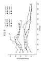
- the sliding members of Examples 1 through 6 and Comparative Example 1 were evaluated on the properties of their friction coefficients ( ⁇ ) under no lubrication condition.
- the evaluation was carried out to measure the friction coefficients ( ⁇ ) of the sliding members of Examples 1 through 6 and Comparative Example 1 with a machine testing laboratory type friction/abrasion tester under the following conditions: No lubrication; Speed of 160 rpm (or sliding speed of 2 cm/second); The sliding area of the test pieces are 2cm2. Load increasing at the rate of 10 kgf per 2 minutes; and Mating member made of high carbon content chromium steel for bearing (SUJ2 as per JIS, hereinafter simply referred to as "SUJ2"). The results of the measurement are shown in Figure 1.
- the sliding members of Examples 1 through 4 in which Al2O3 as the inorganic powder was added, exhibited stable friction coefficients ( ⁇ ) with respect to the load fluctuation, i.e., the temperature fluctuation. This characteristic is believed to result from the phenomenon that the removal of Al2O3 particles from the carbon matrix portion balances the adhesion of the carbon matrix portion. It may be assumed also from the fact that the sliding members of Examples 5 and 6, in which the inorganic fibers less likely to remove from the carbon matrix portion were added, exhibited the friction coefficients ( ⁇ ) increasing with the increment of the load.
- the sliding members of Examples 5 and 6, in which ZrO2 as the inorganic fiber was added exhibited high friction coefficients ( ⁇ ) of 0.5 or more, extremely high values, under the load of 40 kgf or more, because the inorganic fiber is less likely to remove from the carbon matrix portion.
- the sliding members of Examples 1 through 6 and Comparative Example 1 and the sliding member of Comparative Example 2 made from a conventional carbon-carbon composite material were evaluated on their properties of the friction coefficients ( ⁇ ) under oil lubrication.
- the evaluation was carried out to measure the friction coefficients ( ⁇ ) of the sliding members of Examples 1 through 6 and Comparative Examples 1 and 2 with an LFW friction/abrasion tester (a Falex Ring and Block tester) under the following conditions at the end of the testing time: Oil lubrication; Load of 15 kgf; Speed of 160 rpm; Testing time of 15 minutes; and Mating member made of SUJ2.
- Block size is 10 x 15.3 x 6.3 m/m. The results of the measurement are shown in Figure 2.
- the sliding nenbers of Example 1 through 4 in which Al2O3 as the inorganic powder was added, had friction coefficients ( ⁇ ) higher than those of the sliding member of Comparative Example 1 and the sliding member of Comparative Example 2 made from the conventional material.
- the sliding members of Examples 1 through 6 and Comparative Examples 1 and 2 were evaluated on their anti-seizure properties under no lubrication condition, i.e., load at seizure under no lubrication condition.
- the evaluation was to measure the load when the sliding members of Examples 1 through 6 and Comparative Examples 1 and 2 suffered from the seizure, and carried out with the machine testing laboratory type friction/abrasion tester under the following conditions: No lubrication; Speed of 160 rpm; Load increasing at the rate of 10 kgf per 2 minutes; and Mating member made of SUJ2. The results of the measurement are shown in Figure 3.
- Example 1 through 6 had high friction coefficients ( ⁇ ) under no lubrication condition, they exhibited the load at seizure substantially equal to those of Comparative Examples 1 and 2.
- the sliding member of Comparative Example 2 made from the conventional carbon-carbon composite material, the liquid carbonaceous material used as the binder generates volatile substances during the burning, thereby forming pores. The pores accordingly deteriorated the boundary adhesion between the reinforcement and the binder.
- the sliding member of Comparative Example 2 employed the carbonized or graphitized fiber working as the reinforcement and the preliminarily carbonized liquid carbonaceous material working as the binder. As a result, they had different physical properties on the strength, the shrinkage rate and the like when they were burned, thereby deteriorating the boundary adhesion between the reinforcement and the binder.
- Optically isotropic coal pitch was supplied in a spinning machine, heated at 340 °C, extruded through a nozzle of the spinning machine by applying a pressure of an inert gas.
- the pitch fiber thus obtained was further heated at 350° C in an oxidizing atmosphere for 2 hours in order to make it infusible.
- infusible preliminarily carbonized carbonaceous fiber was prepared, and had the fiber diameter of 15 ⁇ m and the fiber length of 0.5 mm.
- a mixture was then prepared which included 30 % by weight of the thus obtained infusible preliminarily carbonized carbonaceous fiber as the reinforcement and 70 % by weight of the self-sintering carbonaceous powder comprising the coal tar mesocarbon microbeads and working as the binder.
- the coal tar mesocarbon microbeads had the average particle diameter of 7 ⁇ m.
- the resulting composite bodies were burned by increasing the temperature from an ordinary temperature to 1000 °C at the rate of 150 °C/hour and by maintaining the temperature of 1000 °C for 1 hour under an ordinary pressure in a non-oxidizing atmosphere, thereby sintering and solidifying the preliminarily carbonized carbonaceous fiber and the self-sintering carbonaceous powder.
- the sintered composite bodies were further sintered by increasing the temperature to 2000 °C at the rate of 500 °C/hour and by maintaining the temperature of 2000 °C for 20 minutes in a non-oxidizing atmosphere.
- the sliding members of Example 7 were thus obtained.
- Example 8 boron nitride powders of the average particle diameters of 2.0 ⁇ m (produced by Kyoritsu Yogyo Co., Ltd.), 0.6 ⁇ m (produced by Shin-etsu Kagaku Co., Ltd.), and 9.3 ⁇ m (produced by Shin-etsu Kagaku Co., Ltd.) were employed as the boron compound powder.
- the sliding members of Example 8 were prepared in the same manner as Example 7.
- Example 9 chromium boride powders of the average particle diameters of 1.8 ⁇ m (produced by Nihon Shin Kinzoku Co., Ltd.) and 4.4 ⁇ m (produced by Nihon Shin Kinzoku Co., Ltd.) were employed as the boron compound powder.
- the sliding members of Example 9 were prepared in the same manner as Example 7.
- Example 10 titanium boride powders of the average particle diameters of 1.4 ⁇ m (produced by Nihon Shin Kinzoku Co., Ltd.) and 5.0 ⁇ m (produced by Kyoritsu Yogyo Co., Ltd.) were employed as the boron compound powder.
- the sliding members of Example 10 were prepared in the same manner as Example 7.
- tantalum boride powder of the average particle diameter of 0.7 ⁇ m (produced by Nihon Shin Kinzoku Co., Ltd.) was employed as the boron compound powder.
- the sliding member of Example 11 was prepared in the same manner as Example 7.
- Example 12 zirconium boride powders of the average particle diameters of 2.0 ⁇ m (produced by Nihon Shin Kinzoku Co., Ltd.) and 4.0 ⁇ m (produced by Nihon Shin Kinzoku Co., Ltd.) were employed as the boron compound powder.
- the sliding members of Example 12 were prepared in the same manner as Example 7.
- Example 7 Seventy parts by weight of the self-sintering carbonaceous powder comprising the coal tar mesocarbon microbeads having the average particle diameter of 7 ⁇ m and employed as the binder in Example 7 was only added to 30 parts by weight of the infusible preliminarily carbonized carbonaceous fiber working as the reinforcement to make a composite body. Other than this arrangement, namely other than that the composite body is free from the boron compound powder, the sliding member of Comparative Example 3 was prepared in the sane manner as Example 7.
- the sliding members of Comparative Examples 4 and 5 were prepared, and they were respectively made from a commercially available conventional carbon fiber reinforced carbon material (produced by Diahitoco Co., Ltd.) and S45C steel material (as per JIS).
- the commercially available conventional carbon fiber reinforced carbon material was one made by impregnating petroleum pitch into carbonaceous fiber and thereafter sintering them at 2000 °C in an inert gas atmosphere.
- the sliding members of Examples 1 through 5 and Comparative Examples 3 through 5 were evaluated on their anti-seizure properties under no lubrication condition, and the evaluation was carried out with the machine testing laboratory type friction/abrasion tester in a manner similar to Evaluation 3 under the following conditions: No lubrication; Speed of 160 rpm; Load increasing at the rate of 10 kgf per 2 minutes; and Mating member made of SUJ2.
- the friction coefficients ( ⁇ ) of the sliding members were also measured at the loads of 100 kgf/cm2 and 150 kgf./cm2. The results of the measurements are shown in Table 2.
- the sliding members of Examples 7, 9, 10 and 12 had remarkably improved abrasion resistance with respect to the sliding member of Comparative Example 4 comprising the commercially available carbon fiber reinforced carbon material.
- the improvement is believed to result from the same reason that the abrasion resistance of the sliding members of Examples 1 through 6 was improved.
- Example 13 the following 6 kinds of inorganic boride were employed, other than the addition of the inorganic boride, the sliding members of Example 13 were prepared in the same manner as Example 1. Namely, CoB having the average particle diameter of 4.6 ⁇ m, B4C having the average particle diameter of 1.9 ⁇ m (employed in Example 7), TiB having the average particle diameter of 1.4 ⁇ m (employed in Example 10), ZrB2 having the average particle diameter of 2.0 ⁇ m (employed in Example 12), BN having the average particle diameter of 9.3 ⁇ m (employed in Example 8) and TaB2 having the average particle diameter of 0.7 ⁇ m (employed in Example 11) were employed as the inorganic powder. Besides, the addition amounts of these 6 kinds of inorganic boride were all set at 5 % by weight.
- Example 14 the following 3 kinds of inorganic carbide were employed, other than the addition of the inorganic carbide, the sliding members of Example 14 were prepared in the same manner as Example 1. Namely, TiC having the average particle diameter of 1.5 ⁇ m, TaC having the average particle diameter of 1.9 ⁇ m, and ZrC having the average particle diameter of 0.8 ⁇ m were employed as the inorganic powder. Besides, the addition amounts of these 3 kinds of inorganic carbide were all set at 5 % by weight.
- Example 15 the following 5 kinds of inorganic nitride were employed, other than the addition of the inorganic nitride, the sliding members of Example 15 were prepared in the same manner as Example 1. Namely, TiN having the average particle diameter of 1.3 ⁇ m, TiN having the average particle diameter of 0.5 ⁇ m, AlN having the average particle diameter of 1.4 ⁇ m, Cr2N having the average particle diameter of 4 ⁇ m, and TaN having the average particle diameter of 3 ⁇ m were employed as the inorganic powder. Besides, the addition amounts of these 5 kinds of inorganic nitride were all set at 5 % by weight.
- Example 16 the following 3 kinds of inorganic oxide were employed, other than the addition of the inorganic oxide, the sliding members of Example 16 were prepared in the same manner as Example 1. Namely, TiO2 having the average particle dianeter of 3 ⁇ m, Al2O3 having the average particle diameter of 0.5 ⁇ m (employed in Examples 1 and 2), and MgO having the average particle dianeter of 0.6 ⁇ m were employed as the inorganic powder. Besides, the addition amounts of these 3 kinds of inorganic oxide were all set at 5 % by weight.
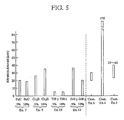
- Example 13 The 6 sliding members of Example 13, the 3 sliding members of Example 14, the 5 sliding members of Example 15, and the 3 sliding members of Example 16 prepared in the above-mentioned manner were evaluated on their friction coefficient ( ⁇ ) properties under no lubrication condition.
- the evaluation was carried out similarly to Evaluation 2 to measure their friction coefficients ( ⁇ ), but under no lubrication condition.
- the load was varied in the range of 25 to 75 kgf/cm2 .
- the results of the measurement are shown in Figure 6.
- the positions of the horizontal line segments in Figure 6 specify the friction coefficients ( ⁇ ).
- Example 17 through 22 BN was enployed as the inorganic powder, other than the addition of BN, the sliding members of Example 17 through 22 were prepared in the same manner as Example 1.
- BN having the average particle diameter of 0.6 ⁇ m employed in Example 8 was employed, and the addition anounts were set at 5 and 10 % by weight respectively.
- BN having the average particle diameter of 2 ⁇ m employed in Example 8 was employed, and the addition amounts were set at 5 and 10 % by weight respectively.
- BN having the average particle diameter of 9.3 ⁇ m employed in Example 8) was employed, and the addition amounts were set at 5 and 10 % by weight respectively.
- Eight sliding members of Examples 23 through 30 were prepared in the same manner as Example 1 except that Al2O3 was employed as the inorganic powder in the sliding members of Examples 23 through 26 and that TiB2 was employed as the inorganic powder in the sliding members of Example 27 through 30.
- Al2O3 having the average particle diameter of 0.5 ⁇ m was employed, and the addition amounts were set at 5 and 10 % by weight respectively
- Al2O3 having the average particle diameter of 4 ⁇ m was employed, and the addition amounts were set at 5 and 10 % by weight respectively.
- Example 31 In the sliding members of Example 31, the following 8 kinds of inorganic boride were employed, other than the addition of the inorganic boride, the 8 sliding members of Example 31 were prepared in the same manner as Example 1. Namely, TiB2 having the average particle diameter of 4 ⁇ m (employed in Examples 29 and 30), TiB2 having the average particle diameter of 1.4 ⁇ m (employed in Exanple 10), ZrB2 having the average particle diameter of 4 ⁇ m (employed in Example 12), ZrB2 having the average particle diameter of 2 ⁇ m (employed in Example 12), NiB2 having the average particle diameter of 4.3 ⁇ m, B4C having the average particle diameter of 1.9 ⁇ m (employed in Example 7), B4C having the average particle diameter of 5 ⁇ m (employed in Example 7), and B4C having the average particle diameter of 0.5 ⁇ m (employed in Example 7) were employed as the inorganic powder. Besides, the addition amounts of these 8 kinds of inorganic boride were all set at 5 % by weight.
- Example 32 In the sliding members of Example 32, the following 4 kinds of inorganic carbide were employed, other than the addition of the inorganic carbide, the 4 sliding members of Example 32 were prepared in the same manner as Example 1. Namely, TiC having the average particle diameter of 0.7 ⁇ m, TiC having the average particle diameter of 1.4 ⁇ m, TaC having the average particle diameter of 1.9 ⁇ m (employed in Example 14), and ZrC having the average particle diameter of 0.8 ⁇ m (employed in Example 14) were employed as the inorganic powder. Besides, the addition amounts of these 4 kinds of inorganic carbide were all set at 5 % by weight.
- Example 33 In the sliding members of Example 33, the following 7 kinds of inorganic nitride were employed, other than the addition of the inorganic nitride, the 7 sliding members of Example 33 were prepared in the same manner as Example 1. Namely, TiN having the average particle diameter of 0.5 ⁇ m (employed in Example 15), TiN having the average particle diameter of 1.3 ⁇ m (employed in Example 15), TaN having the average particle diameter of 3.1 ⁇ m, ZrN having the average particle diameter of 1.4 ⁇ m, BN having the average diameter of 4.3 ⁇ m, AlN having the average particle diameter of 2.6 ⁇ m, and AlN having the average particle diameter of 1.4 ⁇ m (employed in Example 15) were employed as the inorganic powder. Besides, the addition amounts of these 7 kinds of inorganic nitride were all set at 5 % by weight.
- Example 34 In the sliding members of Example 34, the following 6 kinds of inorganic oxide were employed, other than the addition of the inorganic oxide, the 6 sliding members of Example 34 were prepared in the same manner as Example 1. Namely, Al2O3 having the average particle diameter of 0.5 ⁇ m (employed in Examples 1 and 2), Al2O3 having the average particle diameter of 4 ⁇ m (employed in Examples 3 and 4), TiO2 having the average particle diameter of 3 ⁇ m (employed in Example 16), TiO2 having the average diameter of 3.4 ⁇ m, ZrO2 having the average diameter of 1 ⁇ m, and MgO having the average particle diameter of 0.3 ⁇ m were employed as the inorganic powder. Besides, the addition amounts of these 6 kinds of inorganic oxide were all set at 5 % by weight.
- Example 31 The 8 sliding members of Example 31, the 4 sliding members of Example 32, the 7 sliding members of Example 33, and the 6 sliding members of Example 34 prepared in the above-mentioned manner were evaluated on their abrasion resistance under oil lubrication condition. The evaluation was carried out similarly to Evaluation 4. The results of the measurement are shown in Figure 9. The positions of the vertical short line segments specify the abrasion amounts.
- the 25 sliding members of Examples 31 through 34 in total exhibited the abrasion amounts equivalent to or as less as approximately one-third of the abrasion amount exhibited by the sliding member of Comparative Example 1.
- the sliding member of Comparative Example 1 was prepared for evaluating the sliding members of Examples 1 through 6, composed of the composite body including 30 parts by weight of the tar-treated infusible preliminarily carbonized carbonaceous fiber as the reinforcement and 70 parts by weight of the self-sintering carbonaceous powder only added thereto, and prepared by sintering the composite body free from the addition of the inorganic powder.
- the self-sintering carbonaceous powder comprised the coal tar mesocarbon microbeads of the average particle diameter of 7 ⁇ m and worked as the binder.
- the sliding member of Comparative Example 2 exhibited the abrasion amount of 370 ⁇ m. Accordingly, all of the 25 sliding members of Examples 31 through 34 were exhibited the abrasion amounts as less as approximately one-tenth to one-fortieth of the abrasion amount exhibited by the sliding member of Comparative Example 2. Thus, the abrasion resistance of the sliding members of Examples 31 through 34 was found to be remarkably improved.
- the sliding members of Examples 35 and 36 were prepared in the same manner as Example 1 except that TiB2 was employed as the inorganic powder in the sliding member of Examples 35 and that B4C was employed as the inorganic powder in the sliding member of Example 36.
- TiB2 having the average particle diameter of 1.0 ⁇ m was employed, the addition amount was varied variously, and the measurements on the density, the abrasion amount and the bending strength were carried out as described in the following Evaluation 11.
- the sliding members of Examples 35 and 36 were molded into test pieces having the size of 10 mm in length x 30 mm in width x 10 mm in thickness. Then, the cross head speed was set at 1 mm/min., and the loads at the time of the breakage of the test pieces were measured in order to evaluate the bending strength of the sliding members of Examples 35 and 36. The results of the measurement are illustrated in Figure 12. As can be seen from Figure 12, the bending strength of the sliding members of Examples 35 and 36 decreased as the inorganic powder addition amounts increased. Accordingly, it is necessary to select an appropriate inorganic powder addition amount and give a sliding member optimum bending strength depending on an application of a sliding member.
- Example 37 In the sliding members of Example 37, the following 2 kinds of inorganic aluminum compound were employed, other than the addition of the inorganic aluminum compound, the sliding members of Example 37 were prepared in the same manner as Example 1. Namely, Al2O3 and AlN were employed as the inorganic powder. As for Al2O3 , one having the average particle diameter of 0.5 ⁇ m (employed in Examples 1 and 2) and the other having the average particle diameter of 4 ⁇ m (employed in Examples 3 and 4) were prepared, and the addition amounts of the Al2O3 powders having these 2 kinds of average particle diameters were set at 5 as well as 10 % by weight.
- AlN one having the average particle diameter of 1.4 ⁇ m (employed in Example 15) and the other having the average particle diameter of 2.6 ⁇ m (employed in Example 33) were prepared, and the addition amounts of the AlN powders having these 2 kinds of average particle diameters were set at 5 as well as 10 % by weight.
- Example 38 In the sliding members of Example 38, the following 2 kinds of inorganic boron compound were employed, other than the addition of the inorganic boron compound, the sliding members of Example 38 were prepared in the same manner as Example 1. Namely, B4C and BN were employed as the inorganic powder. As for B4C, one having the average particle diameter of 0.5 ⁇ m, the other having the average particle diameter of 1.9 ⁇ m and still another having the average particle diameter of 5.0 ⁇ m were prepared (all employed in Example 7), and the addition amounts of the B4C powders having these 3 kinds of average particle diameters were set at 5 as well as 10 % by weight.
- B4C and BN were employed as the inorganic powder.
- B4C one having the average particle diameter of 0.5 ⁇ m, the other having the average particle diameter of 1.9 ⁇ m and still another having the average particle diameter of 5.0 ⁇ m were prepared (all employed in Example 7), and the addition amounts of the B4C powders having these 3 kinds of average particle diameters were set at
- BN one having the average particle diameter of 0.6 ⁇ m, the other having the average particle diameter of 2.0 ⁇ m and still another having the average particle diameter of 9.3 ⁇ m were prepared (all employed in Example 8), and the addition amounts of the BN powders having these 3 kinds of average particle diameters were set at 5 as well as 10 % by weight.
- Example 39 the inorganic cobalt compound (CoB) was employed, other than the addition of the inorganic cobalt compound, the sliding member of Example 39 was prepared in the same manner as Example 1. Namely, CoB having the average particle diameter of 4.6 ⁇ m (employed in Example 13) was prepared, and the addition amount of the CoB powder was set at 5 as well as 10 % by weight.
- Example 40 In the sliding members of Example 40, the following 2 kinds of inorganic chromium compound were employed, other than the addition of the inorganic chromium compound, the sliding members of Example 40 were prepared in the same manner as Example 1. Namely, Cr2N and Cr2B were enployed as the inorganic powder. Cr2N having the average particle diameter of 3.9 ⁇ m was prepared, and the addition amount of the Cr2N powder was set at 5 as well as 10 % by weight. As for Cr2B, one having the average particle diameter of 1.8 ⁇ m and the other having the average particle diameter of 4.4 ⁇ m were prepared (all employed in Example 9), and the addition amounts of the Cr2B powders having these 2 kinds of average particle diameters were set at 5 as well as 10 % by weight.
- Example 41 In the sliding members of Example 41, the following 2 kinds of inorganic magnesium compound were employed, other than the addition of the inorganic magnesium compound, the sliding members of Example 41 were prepared in the same manner as Example 1. Namely, MgB2 and MgO were employed as the inorganic powder. MgB having the average particle diameter of 0.5 ⁇ m was prepared, and the addition amount of the MgB2 powder was set at 5 as well as 10 % by weight.
- MgO one having the average particle diameter of 0.2 ⁇ m, the other having the average particle diameter of 0.35 ⁇ m and still another having the average particle diameter of 0.6 ⁇ m (employed in Example 16) were prepared, and the addition amounts of the MgO powders having these 3 kinds of average particle diameters were set at 5 as well as 10 % by weight.
- Example 42 the inorganic nickel compound (NiB) was employed, other than the addition of the inorganic nickel compound, the sliding member of Example 42 was prepared in the same manner as Example 1. Namely, NiB having the average particle diameter of 4.3 ⁇ m (employed in Example 31) was prepared, and the addition amount of the NiB powder was set at 5 as well as 10 % by weight.
- Example 43 the following 3 kinds of inorganic tantalum compound were employed, other than the addition of the inorganic tantalum compound, the sliding members of Example 43 were prepared in the same manner as Example 1. Namely, TaC, TaN and TaB2 were employed as the inorganic powder. TaC having the average particle diameter of 1.9 ⁇ m (employed in Example 14) was prepared, and the addition amount of the TaC powder was set at 5 as well as 10 % by weight. Similarly, TaN having the average particle diameter of 3.1 ⁇ m (employed in Example 33) was prepared, and the addition amount of the TaN powder was set at 5 as well as 10 % by weight. Likewise, TaB2 powder having the average particle diameter of 0.7 ⁇ m (employed in Example 11) was prepared, and the addition amount of the TaB2 powder was set at 5 as well as 10 % by weight.
- Example 44 the following 4 kinds of inorganic titanium compound were employed, other than the addition of the inorganic titanium compound, the sliding members of Example 44 were prepared in the same manner as Example 1. Namely, TiO2, TiC, TiN and TiB2 were employed as the inorganic powder. As for TiO2, one having the average particle diameter of 0.4 ⁇ m and the other having the average particle diameter of 3.3 ⁇ m were prepared, and the addition amounts of the TiO2 powders having these 2 kinds of average particle diameters were set at 5 as well as 10 % by weight.
- TiC one having the average particle diameter of 0.7 ⁇ m and the other having the average particle diameter of 1.4 ⁇ m were prepared (all employed in Example 32), and the addition amounts of the TiC powders having these 2 kinds of average particle diameters were set at 5 as well as 10 % by weight.
- TiN one having the average particle diameter of 0.5 ⁇ m and the other having the average particle diameter of 1.3 ⁇ m were prepared (all employed in Example 15), and the addition amounts of the TiN powders having these 2 kinds of average particle diameters were set at 5 as well as 10 % by weight.
- the first one having the average particle diameter of 1.0 ⁇ m, the second one having the average particle diameter of 1.4 ⁇ m (employed in Example 10), the third one having the average particle diameter of 2.3 ⁇ m and the fourth one having the average particle diameter of 4.0 ⁇ m (employed in Examples 29 and 30) were prepared, and the addition amounts of the TiB2 powders having these 4 kinds of average particle diameters were set at 5 as well as 10 % by weight.
- Example 45 the following 4 kinds of inorganic zirconium compound were employed, other than the addition of the inorganic zirconium compound, the sliding members of Example 45 were prepared in the same manner as Example 1. Namely, ZrO2, ZrC, ZrN and ZrB2 were employed as the inorganic powder. ZrO2 having the average particle diameter of 1.0 ⁇ m (employed in Example 34) was prepared, and the addition amount of the ZrO powder was set at 5 as well as 10 % by weight. Similarly, ZrC having the average particle diameter of 0.8 ⁇ m (employed in Example 14) was prepared, and the addition amount of the ZrC powder was set at 5 as well as 10 % by weight.
- ZrN having the average particle diameter of 1.4 ⁇ m (employed in Example 33) was prepared, and the addition amount of the ZrN powder was set at 5 as well as 10 % by weight.
- ZrB2 one having the average particle diameter of 2.0 ⁇ m and the other having the average particle diameter of 4.0 ⁇ m were prepared (all employed in Example 12), and the addition amounts of the ZrB2 powders having these 2 kinds of average particle diameters were set at 5 as well as 10 % by weight.
- Example 46 Two kinds of sliding members of Example 46 were prepared in the same manner as Example 1 except that Al2O3 fiber and ZrO2 fiber were employed as the inorganic fiber in the sliding members of Example 46.
- Al2O3 fiber having the fiber length of 0.5 mm and the fiber diameter of 5 ⁇ m was prepared, and the addition amount of the Al2O3 fiber was set at 5 as well as 10 % by weight.
- ZrO2 fiber having the fiber length of 0.5 mm and the fiber diameter of 5 ⁇ m (employed in Examples 5 and 6) was prepared, and the addition amount of the ZrO2 fiber was set at 5 as well as 10 % by weight.
- the following raw materials were prepared: 28.6 % by weight of infusible preliminarily carbonized carbonaceous fiber having the fiber diameter of 15 ⁇ m and the fiber length of 0.5 mm and comprising the coal optically isotropic pitch identical to the one employed in Example 1, 66.5 % by weight of self-sintering carbonaceous powder comprising the mesocarbon microbeads having the average particle diameter of 6 ⁇ m identical to the one employed in Example 1, and 5 % by weight of Ti powder having the average particle diameter of 8 ⁇ m.
- the composite body was burned by increasing the temperature from an ordinary temperature to 1000 °C at the rate of 150 °C/hour, then by maintaining the temperature of 1000 °C for 1 hour, and thereafter by decreasing the temperature fron 1000 °C to an ordinary temperature under an ordinary pressure in a nitrogen gas atmosphere.
- a first sintered body was thus prepared. After measuring the density of the first sintered body, the first sintered body was further burned by increasing the temperature from an ordinary temperature to 1700 °C at the rate of 500 °C/hour, then by maintaining the temperature of 1700 °C for 20 minutes, and thereafter by decreasing the temperature fron 1700 °C to an ordinary temperature under an ordinary pressure in a nitrogen gas atmosphere.
- a second sintered body namely a sliding member of Example 47, was thus prepared.
- a composite body and a first sintered body of Exanple 48 was prepared by employing the same raw materials and in the same manner as described in Example 47 except that Ni powder having the average particle diameter of 4 ⁇ m was employed. After measuring the density of the first sintered body thus prepared, the first sintered body was further burned by increasing the temperature from an ordinary temperature to 1300 °C at the rate of 500 °C/hour, then by maintaining the temperature of 1300 °C for 20 minutes, and thereafter by decreasing the temperature from 1300 °C to an ordinary temperature under an ordinary pressure in a nitrogen gas atmosphere. A second sintered body, namely a sliding member of Example 48, was thus prepared.
Abstract
Description
- The present invention relates to a sliding member having high strength and excellent heat resistance, abrasion resistance and oxidation resistance. The sliding member is suitable for making a brake shoe, a brake lining, a brake pad, a bush, a thrust washer, a piston ring, vanes, rotors and sleeves of pumps, a bearing for a high temperature application and the like for an aircraft, a racing car and so on.
- The sliding member of the present invention can be applied to both of a dry type friction member and a wet type friction member. Further, the sliding member of the present invention can be made into a sliding member having a low friction coefficient and excellent anti-seizure properties under a dry sliding condition and being applicable to a mechanical structural body, thereby contributing to reduce the frictional loss thereof.
- A sliding member used in a brake shoe component member the like for an aircraft, a racing car and so on especially requires heat resistance and abrasion resistance. On the contrary, since a sliding portion of a mechanical structural body has poor anti-seizure properties, the sliding portion is usually used under an oil lubrication condition. As for a sliding member used under a dry condition, a sintered material impregnated with an oil, a copper sintered alloy and a carbon material have been well known. As for the carbon material, the following carbon materials have been used, i.e., a carbon material made by burning and solidifying a carbonaceous powder and the other carbon material made by sintering a carbonaceous powder at a high temperature to graphitize the carbonaceous powder.
- Recently, carbon fiber reinforced carbon has been provided for the above-mentioned applications, and is said to be a material improving the strength of the conventional carbon materials. According to Japanese Unexamined Patent Publication (KOKAI) No. 206351/1988, this carbon fiber reinforced carbon is produced by impregnating a liquid carbonaceous material, such as tar, pitch and thermosetting resin, which works as a binder into carbon fiber which works as a reinforcement and which has been carbonized or graphitized and further subjected to a surface treatment like oxidation. Then, the resulting binder impregnated carbon fiber is burned in an inert gas atmosphere. If necessary, the resulting sintered product is graphitized thereafter.
- Since the carbon fiber reinforced carbon thus produced uses the liquid carbonaceous material as the binder, volatile substances are generated by the decomposition of the liquid carbonaceous material during the burning, thereby forming pores. Accordingly, the boundary adhesion between the reinforcement and the binder deteriorates, and the density of the product decreases. Consequently, the product is inferior in the strength and the abrasion resistance.
- To solve the above-mentioned problems, the pores of the product have been repeatedly filled with a liquid impregnant working as a binder, and the product has been repeatedly re-burned to decrease the porosity. However, in spite of these complicated processes, the product thus obtained has been still porous. In addition, these complicated processes have resulted in the increasing manufacturing cost.
- Further, the above-mentioned conventional carbon fiber reinforced carbon suffers from a low friction coefficient (µ) especially under a low load.
- Furthermore, though the above-mentioned conventional carbon fiber reinforced carbon has been known to be superior in the anti-seizure properties, it is seized at the load of 50 to 75 kgf/cm² which is as much as 3 to 4 times that of steel for a structural application under a dry condition. In addition, since the carbon fiber reinforced carbon only exhibits the friction coefficient (µ) of 0.2 to 0.5 under a dry condition, it is not a material of a low friction coefficient, nor a suitable material for a sliding portion of a mechanical structural body.
- The present invention has been developed in view of these problems, and it is therefore an object of the present invention to provide a sliding member having high strength and an excellent friction/abrasion property and being manufacturable at a low cost.
- Further, it is another object of the present invention to provide a sliding member having high strength, excellent abrasion resistance, high anti-seizure properties, i.e., exhibiting a load of 100 kgf/cm² or more at seizure, and exhibiting a friction coefficient of 0.15 or less.
- A sliding member according to the present invention has a predetermined shape, and comprises a sintered body obtained by sintering a composite body comprising: preliminarily carbonized carbonaceous fiber; inorganic powder or inorganic fiber; and self-sintering carbonaceous powder with the preliminarily carbonized carbonaceous fiber and the inorganic powder or the inorganic fiber buried therein.
- In particular, a sliding member according to the present invention which is suitable for a sliding portion of a mechanical structural body has a predetermined shape, and comprises a sintered body obtained by sintering a composite body comprising: preliminarily carbonized carbonaceous fiber; boron compound powder; and self-sintering carbonaceous powder with the preliminarily carbonized carbonaceous fiber and the boron compound powder buried therein.
- The shape of the sliding member is not restricted particularly. For example, the sliding member may be made into a predetermined shape of a brake shoe, a brake lining, a brake pad, a piston ring, a bearing and the like.
- The preliminarily carbonized carbonaceous fiber constitutes a reinforcement of the sliding member of the present invention. The raw material of the preliminarily carbonized carbonaceous fiber is not restricted particularly. For example, the raw material may be PAN (polyacrylonitrile), rayon, or pitch and the like.
- Here, the preliminarily carbonized carbonaceous fiber is a carbonaceous fiber which has not been subjected to an ordinary carbonizing treatment. In other words, it is a carbonaceous fiber which can accept further carbonizing when it is further subjected to a heat treatment. To be concrete, when raw pitch is employed, the preliminarily carbonized carbonaceous fiber may be spun fiber itself or infusible fiber obtained by making the spun fiber infusible at a temperature of less than 550 °C. When polymer fiber such as PAN fiber is employed, the preliminarily carbonized carbonaceous fiber may be polymer fiber which has got through a decomposition process and is prior to a graphitizing treatment. As for the carbonaceous fiber of this type, spun pitch fiber obtained by spinning coal or petroleum raw pitch and infusible fiber obtained by making the spun pitch fiber infusible.
- The spinning of the raw pitch and the infusible treatment may be carried out according to ordinary methods, and the conditions therefor are not restricted particularly. In most cases, the pitch fiber may be obtained in the following manner: The raw pitch is supplied in a spinning machine, heated at the temperature of about 300 to 400 °C, and extruded through a nozzle of the spinning machine by applying a pressure of an inert gas. The pitch fiber thus obtained may be made into the infusible pitch fiber by heating the pitch fiber at 150 to 500 °C for 0.5 to 5 hours in an oxidizing atmosphere. Here, the raw pitch may be either optically isotropic or optically anisotropic.
- As for the fiber length of the preliminarily carbonized carbonaceous fiber, either the short fiber or the long fiber thereof may be used. When using the short fiber, the fiber length thereof may be 0.01 to 50 mm, and particularly the short fiber having the length of 0.03 to 10 mm is preferred in view of the easy mixing and the aspect ratio. When it is too long, the fibers get entangled to deteriorate the dispersibility and finally the product isotropy, one of the important properties of the product. When it is less than 0.01 mm, the strength of the product decreases sharply. As for the fiber diameter thereof, 5 to 25 µm is preferred. Further, a non-woven fabric or a coating fabric made of these fibers may be used.
- In addition, the preliminarily carbonized carbonaceous fiber may be preferably subjected to a surface treatment using a viscous material such as tar, pitch and organic polymer in order to improve the affinity with a binder. This surface treatment may be carried out by stirring 100 parts by weight of the preliminarily carbonized carbonaceous fiber with 100 to 1000 parts by weight of the viscous material. The mixture is then washed with an organic solvent, and dried.
- The tar or pitch used for the surface treatment may be derived either from coal or petroleum. When the pitch is used, a heat treatment of about 140 to 170 °C is required during the stirring. The tar is accordingly more preferred for the viscous material. Further, coal tar is much more preferred in view of the carbonization material loss in the subsequent carbonizing and graphitizing processes.
- The organic polymer used for the surface treatment may be phenol resin, polyvinyl chloride, polyvinyl alcohol and the like.
- The organic solvent used for the washing of the surface treatment may be an aromatic solvent such as toluene and xylene. The washing is carried out by stirring 100 parts by weight of the mixture of the preliminarily carbonized carbonaceous fiber and the viscous material with 100 to 1000 parts by weight of the organic solvent, thereby removing light oil components containing many volatile substances. The preliminarily carbonized carbonaceous fiber thus washed is dried by heating and/or depressurizing in a non-oxidizing atmosphere such as nitrogen and argon. The drying is not restricted to the above as far as the organic solvent employed for the washing can be removed.
- Further, the preliminarily carbonized carbonaceous fiber thus surface-treated and dried is dispersed, if required, since the dried preliminarily carbonized carbonaceous fiber may sometimes come together in a mass or aggregate. If such is the case, the dispersion may be carried out by an ordinary means such as a powder mill, an atomizer, a pulverizer and the like.
- The inorganic powder or the inorganic fiber constitutes the reinforcement of the sliding member of the present invention together with the preliminarily carbonized carbonaceous fiber. Depending on a specific application of a sliding member to be manufactured, the inorganic powder or the inorganic fiber is added in order to increase the friction coefficient (µ) of the sliding member and make it stable, or in order to give the sliding member high abrasion resistance and high anti-seizure properties even when the sliding member has a friction coefficient (µ) of a low value. The inorganic powder or the inorganic fiber may preferably be one having the melting point of 1000 °C or higher and being not reactable with carbon, and may more preferably be one having the hardness of 1000 Hv or more as well.
- As for the inorganic substance therefor, inorganic oxide, inorganic carbide, inorganic nitride, inorganic boride and the like may be used. The inorganic oxide may be Al₂O₃, TiO₂, ZrO₂, MgO and the like. The inorganic carbide may be B₄C, TiC, TaC, ZrC and the like. The inorganic nitride may be BN, TiN, Cr₂N, TaN, AlN, ZrN and the like. The inorganic boride may be TiB₂, ZrB₂, B₄C, NiB, CoB, BN, TaB₂ and the like. Further, inorganic substances of Fe, Mn, Mo, Ni, Nb, Si, V, Ti, W and the like may be used. Besides, these inorganic substances may be added in their metallic states. Moreover, the inorganic fiber includes whisker and ceramic fiber.
- By selecting an optimum one from the above-mentioned inorganic powders or inorganic fibers, the properties, i.e., the friction coefficient (µ), the abrasion resistance, the anti-seizure properties and the like, may be controlled to optimum properties depending on an application of a sliding member. Particularly, in order to make the sliding member suitable for a sliding portion of a mechanical structural body, namely in order to make a completed product into a sliding member having high strength, excellent abrasion resistance, high anti-seizure properties, i.e., exhibiting a load of 100 kgf/cm² or more at seizure, and exhibiting a friction coefficient of 0.15 or less, a boron compound may be used for the inorganic powder.
- As for the boron compound, it is preferable to use a boron compound which does not decompose or fuse at a temperature less than the sintering temperature. However, a boron compound which decomposes at the sintering temperature may be used in the case that the boron compound, such as MgB₂ and CoB decomposing at a sintering temperature, decomposes to produce boron and the decomposed boron reacts with carbon to produce boron carbide. As for the boron compound, boron carbide, boron nitride and the like may be used. Additionally, boride of Cr, Ti, Ta, Zr, Al, Ni, Mg, Nb, Mn, Fe, V, W and the like may be used. Besides, the additives may be added in their metallic states.
- When the inorganic powder is used as the inorganic substance, the average particle diameter thereof is preferred to fall in the range of 0.1 to 5 µm in view of the affinity with the matrix, the dispersibility and the strength and abrasion resistance of the completed sintered body. It is more preferred to fall in the range of 0.2 to 4 µm.
- When the inorganic fiber is used as the inorganic substance, the diameter and the length thereof are preferred to fall in the ranges of 0.7 to 40 µm and 0.01 to 8 mm respectively in view of the affinity with the matrix, the dispersibility, the strength and abrasion resistance of the completed sintered body and the removability of the inorganic fiber. They are more preferred to fall in the ranges of 1 to 15 µm and 0.05 to 3 mm respectively.
- Particularly, when the boron compound is used as the inorganic powder in order to make the sliding member suitable for a sliding portion of a mechanical structural body, the average particle diameter of the boron compound is preferred to fall in the range of 0.1 to 10 µm, and more preferred to fall in the range of 0.3 to 5 µm. When it is less than 0.1 µm, it is hard to mix the boron compound with the preliminarily carbonized carbonaceous fiber and the self-sintering carbonaceous powder uniformly. When it is more than 10 µm, the possibility of the abnormal or aggressive abrasion increases.
- The self-sintering carbonaceous powder constitutes a binder of the sliding member according to the present invention. The self-sintering carbonaceous powder is a powder having a self-sintering property and being preliminarily carbonized or not being completely carbonized. The self-sintering carbonaceous powder may be derived either from coal or petroleum. To be concrete, mesocarbon microbeads, pulverized bulkmesophase powder, pulverized low temperature calcined coke powder and the like may be used. In particular, the mesocarbon microbeads of coal or petroleum is preferred among them in view of its uniform and stable particle diameter and composition. Further, the mesocarbon microbeads of coal is more preferred in view of the carbonization material loss in the carbonizing process. The self-sintering carbonaceous powder having the average particle diameter of 30 µm or less and the β-resin amount falling in the range of 3 to 50 % is preferred. Furthermore, the β-resin amount may more preferably fall in the range of 6 to 30 %, and it may much more preferably fall in the range of 8 to 25 %.
- The sliding member of the present invention may be manufactured, for instance, by a simple manufacturing process illustrated in Figure 13 and comprising a dry mixing step, a dry molding step and a burning step.
- The preliminarily carbonized carbonaceous fiber, the inorganic powder or the inorganic fiber and the self-sintering cabonaceous powder is mixed and molded into a composite body. The mixing method is not restricted particularly, however it is preferred to uniformly mix the above-mentioned raw materials in order to make the strength and the abrasion resistance of the product isotropic. Here, the composition of the self-sintering carbonaceous powder and the preliminarily carbonized carbonaceous fiber may be 100 parts by weight of the former to 2 to 70 parts by weight of the latter. More preferably, it may be 100 parts by weight of the former to 10 to 50 parts by weight of the latter. Further, the addition amount of the inorganic powder or the inorganic fiber may preferably be 3 to 30 % by weight with respect to the whole amount of the raw materials taken as 100 % by weight. More preferably, it may be 5 to 10 % by weight with respect to the whole amount.
- In particular, when the boron compound is used as the inorganic powder in order to make the sliding member suitable for a sliding portion of a mechanical structural body, the addition amount of the boron compound may preferably be 1 to 50 % by weight with respect to the whole anount of the raw materials taken as 100 % by weight. More preferably, it may be 3 to 35 % by weight with respect to the whole amount. When the addition amount of the boron compound is more than 50 % by weight, the machinability of the sintered body becomes improper and the strength thereof deteriorates slightly.
- The molding operation of the sliding member according to the present invention may be carried out by an ordinary molding method. In the molding operation, a mixture of the preliminarily carbonized carbonaceous fiber, the inorganic powder or the inorganic fiber and the self-sintering carbonaceous powder is usually molded into a predetermined shape in a mold while applying the pressure of 1 to 10 ton/cm². Or the molding operation may be done by the CIP method, the HIP method, the hot pressing method and the like. The molding operation may be carried out at an ordinary temperature to 500 °C in an inert gas atmosphere.
- The composite body is sintered, and made into the sliding member of the present invention. Here, the sintering is to carbonize and solidify the preliminarily carbonized carbonaceous fiber and the self-sintering carbonaceous powder by burning at about 700 to 1500 °C under an ordinary pressure. Further, the thus carbonized and solidified composite body may be graphitized by heating to the sintering temperature or more in a graphitizing furnace, if necessary.
- The conditions of the carbonizing are not restricted particularly. The carbonizing may usually be carried out by increasing the temperature starting at an ordinary temperature to about 1500 °C at the rate of about 0.1 to 300 °C/hour and by keeping the temperature of about 1500 °C for about 0.5 to 10 hours in a non-oxidizing atmosphere. Moreover, also during the sintering, part of the composite body is graphitized by heating to a higher temperature after the carbonizing.
- Likewise, the conditions of the graphitizing are not restricted particularly. The graphitizing may be carried out by increasing the temperature starting at the sintering temperature to the temperature of 1500 to 3000 °C at the rate of about 0.1 to 500 °C/hour and by keeping the temperature of about 1500 to 3000 °C for about 0.5 to 10 hours in a non-oxidizing atmosphere. When the composite body is graphitized, the graphite crystals have grown fully and oriented orderly to improve the density, strength and abrasion resistance of the product.
- In the sliding member of the present invention, the composite body before the sintering comprises: the preliminarily carbonized carbonaceous fiber; the inorganic powder or the inorganic fiber; and the self-sintering carbonaceous powder with the preliminarily carbonized carbonaceous fiber and the inorganic powder or the inorganic fiber buried therein.
- Accordingly, when the composite body is sintered, the preliminarily carbonized carbonaceous fiber working as the reinforcement and the self-sintering carbonaceous powder working as the binder come to have substantially the same physical properties on the strength, the shrinkage rate and the like, because the preliminarily carbonized carbonaceous fiber is uncarbonized or has not been completely carbonized yet. As a result, the boundary adhesion between the preliminarily carbonized carbonaceous fiber and the self-sintering carbonaceous powder has been improved, whereby the high strength and excellent abrasion resistance can be obtained. In short, when the composite body is sintered, both of the preliminarily carbonized ones, i.e., the preliminarily carbonized carbonaceous fiber and the self-sintering carbonaceous powder, shrink by substantially the equal degree and get together, whereby the boundary adhesion therebetween has been improved. Thus, the strength and abrasion resistance of the sliding member have been improved.
- Further, by adding the inorganic powder or the inorganic fiber, a mechanical resistance force is exerted between the sliding member and a mating member, thereby making the friction coefficient (µ) high and stable. Namely, since the added inorganic powder or inorganic fiber exerts a mechanical resistance force to the mating member, the friction coefficient (µ) of the sliding member becomes high and stable.
- For instance, when the inorganic powder is added, the inorganic powder becomes likely to remove from the carbon matrix portion as the increment of load because the inorganic powder is in a powder form. The removal of the inorganic powder balances the adhesion of the carbon matrix, thereby making the friction coefficient (µ) stable against the fluctuation of load. On the contrary, when the inorganic fiber is added, the inorganic fiber becomes less likely to remove from the carbon matrix portion as the increment of load because the inorganic fiber is in a fiber form. Thus, the sliding member comes to exhibit a friction coefficient (µ) of an extremely high value.
- Furthermore, the self-sintering carbonaceous powder working as the binder has got rid of the conventional binder comprising the liquid carbonaceous material as mentioned earlier. Therefore, it is not necessary to carry out the re-impregnating and re-burning for repeatedly filling the pores resulting from the conventional liquid carbonaceous material, and the sliding member of the present invention can be manufactured by the above-mentioned simple process, illustrated in Figure 13 and comprising a dry mixing step, a dry molding step and a burning step, at a low cost accordingly.
- Moreover, by selecting an optimum inorganic powder or inorganic fiber, the friction coefficient (µ) of a completed sliding member can be controlled to an optimum value depending on an application thereof. In particular, in the case that the boron compound is added in order to make the sliding member suitable for a sliding portion of a mechanical structural body, the boron compound is thermally decomposed, thereby generating the liquid phase thereof, when a high load is applied to the sliding member, namely when the sliding member is subjected to a high temperature. The liquid phase of the boron compound improves the anti-seizure properties of the sliding member, and thus it is believed that the friction coefficient (µ) of thereof can be suppressed to a low value.
- For instance, when the inorganic boride is used as the inorganic powder, the friction coefficient (µ) of the sliding member can be controlled in the range of 0.05 to 0.2. When the inorganic carbide is used as the inorganic powder, the friction coefficient (µ) of the sliding member can be controlled in the range of 0.15 to 0.35. When the inorganic nitride is used as the inorganic powder, the friction coefficient (µ) of the sliding member can be controlled in the range of 0.1 to 0.35. When the inorganic oxide is used as the inorganic powder, the friction coefficient (µ) of the sliding member can be controlled in the range of 0.25 to 0.5.
- Here, it is believed that the friction coefficient (µ) of the sliding member is varied greatly by the addition of the inorganic powder or the inorganic fiber because the state of the inorganic powder or the inorganic fiber is varied by the heat generation associating with the sliding movement. For instance, since the oxide has high heat resistance and keeps the particle or fiber configuration during the sliding movement, the sliding member is believed to exhibit a higher friction coefficient (µ) accordingly. Contrary to the oxide, since the boride is decomposed by the heat generation during the sliding movement and produces the liquid phase, the boride is believed to decrease the friction coefficient (µ) of the sliding member.
- In addition, when the preliminarily carbonized carbonaceous fiber is subjected to the surface treatment using the viscous material such as tar, pitch and organic polymer, the wettability of the boundary surface of the preliminarily carbonized carbonaceous fiber increases. The boundary adhesion between the preliminarily carbonized carbonaceous fiber and the self-sintering carbonaceous powder working as the binder has been thus further improved because the affinity between the preliminarily carbonized carbonaceous fiber and the self-sintering carbonaceous powder has been increased.
- As described so far, the sliding member of the present invention has excellent properties such as high strength, high heat resistance, high abrasion resistance, high oxidation resistance and the like, it can be applied to a brake shoe, a brake lining, a brake pad, a bush, a thrust washer, a piston ring, vanes, rotors and sleeves of pumps, a bearing for a high temperature application and the like for an aircraft, a racing car and so on. In adition, it is expected that the sliding member may be applied to electrodes such as electrodes for electrical discharge machining, carbon electrodes and the like.
- A more complete appreciation of the present invention and many of the attendant advantages thereof will be readily obtained as the same becomes better understood by reference to the following detailed description when considered in connection with the accompanying drawings, wherein:
- Figure 1 is a line chart showing the results of the measurement on the friction coefficients (µ under no lubrication condition) of the sliding members of Examples 1 through 6 and Comparative Example 1;
- Figure 2 is a column chart showing the results of the measurement on the friction coefficients (µ under oil lubrication condition) of the sliding members of Examples 1 through 6, Comparative Example 1 and Comparative Example 2 made from a commercially available carbon-carbon composite material;
- Figure 3 is a column chart showing the results of the measurement on the loads at seizure (under no lubrication condition) of the sliding members of Examples 1 through 6 and Comparative Examples 1 and 2;
- Figure 4 is a column chart showing the results of the measurement on the abrasion amounts (under oil lubrication condition) of the sliding members of Examples 1 through 6 and Comparative Examples 1 and 2;
- Figure 5 is a column chart showing the results of the measurement on the abrasion amounts (under oil lubrication condition) of the sliding members of Examples 7, 9, 10 and 12 and Comparative Examples 3 through 5;
- Figure 6 is a diagram showing the results of the measurement on the friction coefficients (µ under no lubrication condition) of the sliding members of Examples 13 through 16 and Comparative Example 1;
- Figure 7 is a line chart showing the results of the measurement on the friction coefficients (µ under no lubrication condition) of the sliding members of Examples 17 through 22;
- Figure 8 is a line chart showing the results of the measurement on the friction coefficients (µ under no lubrication condition) of the sliding members of Examples 23 through 30;
- Figure 9 is a diagram showing the results of the measurement on the abrasion amounts (under oil lubrication) of the sliding members of Examples 31 through 34 and Comparative Examples 1 and 5;
- Figure 10 is a line chart showing the variations of the densities of the sliding members of Examples 35 and 36 with respect to the variations of the inorganic addition anounts thereof:
- Figure 11 is a line chart showing the variations of the abrasion amounts of the sliding members of Examples 35 and 36 with respect to the variations of the inorganic addition amounts thereof;
- Figure 12 is a line chart showing the variations of the bending strength of the sliding members of Examples 35 and 36 with respect to the variations of the inorganic addition amounts thereof; and
- Figure 13 is a block diagram showing a manufacturing process of a sliding member of the present invention.
- Having generally described the present invention, a further understanding can be obtained by reference to certain specific preferred embodiments which are provided herein for purposes of illustration only and are not intended to be limiting unless otherwise specified.
- Preliminarily carbonized carbonaceous fiber comprising infusible fiber was prepared. The infusible fiber was made from optically isotropic coal pitch by an ordinary method, and had the fiber diameter of 15 µm and the fiber length of 0.5 mm. Then, 500 parts by weight of tar was added to 100 parts by weight of this preliminarily carbonized carbonaceous fiber working as the reinforcement. The mixture was stirred at an ordinary temperature for 15 minutes and filtered thereafter. Further, 500 parts by weight of toluene was added thereto, stirred for 30 minutes, filtered, and dried to 150°C in a nitrogen atmosphere for 3 hours to make tar-treated infusible preliminarily carbonized carbonaceous fiber.
- A mixture was then prepared which included 30 % by weight of the tar-treated infusible preliminarily carbonized carbonaceous fiber thus obtained and 70 % by weight of a self-sintering carbonaceous powder comprising coal tar mesocarbon microbeads and working as the binder. The coal tar mesocarbon microbeads had the average particle diameter of 7 µm. Then, 5 % by weight of Al₂O₃ having the average particle diameter of 0.5 µm as the inorganic powder was mixed uniformly with 95 % by weight of the mixture, and a resulting nixture was put into a mold and molded into a composite body having a predetermined shape of a sliding member by applying the molding pressure of 2 ton/cm².
- Next, the resulting composite body was burned by increasing the temperature from an ordinary temperature to 1000 °C at the rate of 150 °C/hour and by maintaining the temperature of 1000 °C for 1 hour under an ordinary pressure in a non-oxidizing atmosphere, thereby sintering and solidifying the preliminarily carbonized carbonaceous fiber and the self-sintering carbonaceous powder. Then, the sintered composite body was further sintered by increasing the temperature to 2000 °C at the rate of 500 °C/hour and by maintaining the temperature of 2000 °C for 20 minutes in a non- oxidizing atmosphere. A sliding member of Example 1 was thus obtained.
- The average particle diameter and the addition amount of Al₂O₃ employed as the inorganic powder in Example 1 were varied as listed in Table 1, and the sliding members of Examples 2 through 4 were prepared in the same manner as Example 1.
- In the sliding members of Examples 5 and 6, ZrO₂ fiber was employed as the inorganic fiber instead of Al₂O₃ employed as the inorganic powder in Example 1. ZrO₂ fiber was 5 µm in diameter and 0.5 mm in length, and 5 and 10 % by weight thereof with respect to the whole amount were added respectively in Examples 5 and 6. Similarly, the sliding members of Examples 5 and 6 were prepared in the same manner as Example 1.
- Seventy parts by weight of the self-sintering carbonaceous powder comprising the coal tar mesocarbon microbeads having the average particle diameter of 7 µm and employed as the binder in Example 1 was only added
TABLE 1 Composition (% by weight) Carbonaceous Powder Carbonaceous Fiber Aℓ₂O₃ Powder ZrO₂ Fiber Par. Dia. / Amount (µm) Dia.,Length / Amount (µm, mm) Ex. 1 66.5 28.5 0.5 / 5 None Ex. 2 63.0 27.0 0.5 / 10 None Ex. 3 66.5 28.5 4 / 5 None Ex. 4 63.0 27.0 4 / 10 None Ex. 5 66.5 28.5 None 5, 0.5/5 Ex. 6 63.0 27.0 None 5, 0.5/10 - The sliding members of Examples 1 through 6 and Comparative Example 1 were evaluated on the properties of their friction coefficients (µ) under no lubrication condition. The evaluation was carried out to measure the friction coefficients (µ) of the sliding members of Examples 1 through 6 and Comparative Example 1 with a machine testing laboratory type friction/abrasion tester under the following conditions:
No lubrication;
Speed of 160 rpm (or sliding speed of 2 cm/second);
The sliding area of the test pieces are 2cm².
Load increasing at the rate of 10 kgf per 2 minutes; and
Mating member made of high carbon content chromium steel for bearing (SUJ2 as per JIS, hereinafter simply referred to as "SUJ2").
The results of the measurement are shown in Figure 1. - It is apparent from Figure 1 that the sliding members of Examples 1 through 6 had higher friction coefficients (µ) under low load than Comparative Example 1 did. This is believed as follows: A mechanical resistance force was exerted between the sliding members and the mating member because the Al₂O₃ or ZrO₂ as the inorganic powder or the inorganic fiber were added in the sliding members of Examples 1 through 6.
- Moreover, the sliding members of Examples 1 through 4, in which Al₂O₃ as the inorganic powder was added, exhibited stable friction coefficients (µ) with respect to the load fluctuation, i.e., the temperature fluctuation. This characteristic is believed to result from the phenomenon that the removal of Al₂O₃ particles from the carbon matrix portion balances the adhesion of the carbon matrix portion. It may be assumed also from the fact that the sliding members of Examples 5 and 6, in which the inorganic fibers less likely to remove from the carbon matrix portion were added, exhibited the friction coefficients (µ) increasing with the increment of the load.
- Hence, the sliding members of Examples 5 and 6, in which ZrO₂ as the inorganic fiber was added, exhibited high friction coefficients (µ) of 0.5 or more, extremely high values, under the load of 40 kgf or more, because the inorganic fiber is less likely to remove from the carbon matrix portion.
- The sliding members of Examples 1 through 6 and Comparative Example 1 and the sliding member of Comparative Example 2 made from a conventional carbon-carbon composite material were evaluated on their properties of the friction coefficients (µ) under oil lubrication. The evaluation was carried out to measure the friction coefficients (µ) of the sliding members of Examples 1 through 6 and Comparative Examples 1 and 2 with an LFW friction/abrasion tester (a Falex Ring and Block tester) under the following conditions at the end of the testing time:
Oil lubrication;
Load of 15 kgf;
Speed of 160 rpm;
Testing time of 15 minutes; and
Mating member made of SUJ2.
Block size is 10 x 15.3 x 6.3 m/m.
The results of the measurement are shown in Figure 2. - As can be seen fron Figure 2, the sliding nenbers of Example 1 through 4, in which Al₂O₃ as the inorganic powder was added, had friction coefficients (µ) higher than those of the sliding member of Comparative Example 1 and the sliding member of Comparative Example 2 made from the conventional material.
- The sliding members of Examples 1 through 6 and Comparative Examples 1 and 2 were evaluated on their anti-seizure properties under no lubrication condition, i.e., load at seizure under no lubrication condition. The evaluation was to measure the load when the sliding members of Examples 1 through 6 and Comparative Examples 1 and 2 suffered from the seizure, and carried out with the machine testing laboratory type friction/abrasion tester under the following conditions:
No lubrication;
Speed of 160 rpm;
Load increasing at the rate of 10 kgf per 2 minutes; and
Mating member made of SUJ2.
The results of the measurement are shown in Figure 3. - As can be seen from Figure 3, although the sliding members of Example 1 through 6 had high friction coefficients (µ) under no lubrication condition, they exhibited the load at seizure substantially equal to those of Comparative Examples 1 and 2.
- Further, the sliding members of Examples 1 through 6 and Comparative Examples 1 and 2 were evaluated on their abrasion resistance under oil lubrication condition. An abrasion test was carried out with the LFW friction/abrasion tester under the following conditions, and their abrasion amounts were measured at the end of the testing time:
Oil lubrication;
Load of 15 kgf;
Speed of 160 rpm;
Testing time of 15 minutes; and
Mating member made of SUJ2.
The results of the measurement are shown in Figure 4. - As can be seen from Figure 4, although the sliding members of Example 1 through 6 had high friction coefficients (µ) under oil lubrication condition, they had improved the abrasion resistance far better than the sliding member of Comparative Example 2 made from the conventional carbon-carbon composite material did, and their abrasion resistance were substantially equal to that of the sliding member of Comparative Example 1. This is believed as follows: Since the sliding members of Examples 1 through 6 employed the preliminarily carbonized ones for both of the carbonaceous fiber working as the reinforcement and the carbonaceous powder working as the binder, the carbonaceous fiber and the powder came to have substantially the same physical properties on the strength, the shrinkage rate and the like when they were carbonized, thereby improving the boundary adhesion between the carbonaceous fiber and the carbonaceous powder. In addition, it is also believed as follows: Since the sliding member of Examples 1 through 6 employed the preliminarily carbonized carbonaceous fiber surface-treated with the tar, the wettability of the preliminarily carbonized carbonaceous fiber is further increased, thereby further improving the boundary adhesion between the carbonaceous fiber and the carbonaceous powder.
- On the contrary, in the sliding member of Comparative Example 2 made from the conventional carbon-carbon composite material, the liquid carbonaceous material used as the binder generates volatile substances during the burning, thereby forming pores. The pores accordingly deteriorated the boundary adhesion between the reinforcement and the binder. Additionally, the sliding member of Comparative Example 2 employed the carbonized or graphitized fiber working as the reinforcement and the preliminarily carbonized liquid carbonaceous material working as the binder. As a result, they had different physical properties on the strength, the shrinkage rate and the like when they were burned, thereby deteriorating the boundary adhesion between the reinforcement and the binder.
- Optically isotropic coal pitch was supplied in a spinning machine, heated at 340 °C, extruded through a nozzle of the spinning machine by applying a pressure of an inert gas. The pitch fiber thus obtained was further heated at 350° C in an oxidizing atmosphere for 2 hours in order to make it infusible. Thus, infusible preliminarily carbonized carbonaceous fiber was prepared, and had the fiber diameter of 15 µm and the fiber length of 0.5 mm.
- A mixture was then prepared which included 30 % by weight of the thus obtained infusible preliminarily carbonized carbonaceous fiber as the reinforcement and 70 % by weight of the self-sintering carbonaceous powder comprising the coal tar mesocarbon microbeads and working as the binder. The coal tar mesocarbon microbeads had the average particle diameter of 7 µm. Then, 5 % by weight of boron carbide compound powders having the average particle diameters of 1.9 µm (produced by Kyoritsu Yogyo Co., LTd.), 5.0 µm (produced by Denki Kagaku Co., Ltd.), 0.5 µm (produced by Denki Kagaku Co., Ltd.) were respectively added to and mixed uniformly with 95 % by weight of the mixture, and resulting mixtures were respectively put into a mold and molded into composite bodies having a predetermined shape of a sliding member by applying the molding pressure of 2 ton/cm².
- Next, the resulting composite bodies were burned by increasing the temperature from an ordinary temperature to 1000 °C at the rate of 150 °C/hour and by maintaining the temperature of 1000 °C for 1 hour under an ordinary pressure in a non-oxidizing atmosphere, thereby sintering and solidifying the preliminarily carbonized carbonaceous fiber and the self-sintering carbonaceous powder. Then, the sintered composite bodies were further sintered by increasing the temperature to 2000 °C at the rate of 500 °C/hour and by maintaining the temperature of 2000 °C for 20 minutes in a non-oxidizing atmosphere. The sliding members of Example 7 were thus obtained.
- Further, 10 % by weight of boron carbide compound powders having the average particle diameters of 1.9 µm (produced by Kyoritsu Yogyo Co., LTd.), 5.0 µm (produced by Denki Kagaku Co., Ltd.), 0.5 µm (produced by Denki Kagaku Co., Ltd.) were respectively added to and mixed uniformly with 90 % by weight of the mixture including 30 % by weight of the infusible preliminarily carbonized carbonaceous fiber as the reinforcement and 70 % by weight of the self-sintering carbonaceous powder comprising the coal tar mesocarbon microbeads having the average particle diameter of 7 µm and working as the binder, and resulting mixtures were molded and sintered in the same manner as above-mentioned. The other sliding members of Example 7 were thus obtained.
- In the sliding members of Example 8, boron nitride powders of the average particle diameters of 2.0 µm (produced by Kyoritsu Yogyo Co., Ltd.), 0.6 µm (produced by Shin-etsu Kagaku Co., Ltd.), and 9.3 µm (produced by Shin-etsu Kagaku Co., Ltd.) were employed as the boron compound powder. Other than the addition of the boron nitride powders, the sliding members of Example 8 were prepared in the same manner as Example 7.
- In the sliding members of Example 9, chromium boride powders of the average particle diameters of 1.8 µm (produced by Nihon Shin Kinzoku Co., Ltd.) and 4.4 µm (produced by Nihon Shin Kinzoku Co., Ltd.) were employed as the boron compound powder. Other than the addition of the chromium boride powders, the sliding members of Example 9 were prepared in the same manner as Example 7.
- In the sliding members of Example 10, titanium boride powders of the average particle diameters of 1.4 µm (produced by Nihon Shin Kinzoku Co., Ltd.) and 5.0 µm (produced by Kyoritsu Yogyo Co., Ltd.) were employed as the boron compound powder. Other than the addition of the titanium boride powders, the sliding members of Example 10 were prepared in the same manner as Example 7.
- In the sliding member of Example 11, tantalum boride powder of the average particle diameter of 0.7 µm (produced by Nihon Shin Kinzoku Co., Ltd.) was employed as the boron compound powder. Other than the addition of the tantalum boride powder, the sliding member of Example 11 was prepared in the same manner as Example 7.
-
- In the sliding members of Example 12, zirconium boride powders of the average particle diameters of 2.0 µm (produced by Nihon Shin Kinzoku Co., Ltd.) and 4.0 µm (produced by Nihon Shin Kinzoku Co., Ltd.) were employed as the boron compound powder. Other than the addition of the zirconium boride powders, the sliding members of Example 12 were prepared in the same manner as Example 7.
- Seventy parts by weight of the self-sintering carbonaceous powder comprising the coal tar mesocarbon microbeads having the average particle diameter of 7 µm and employed as the binder in Example 7 was only added to 30 parts by weight of the infusible preliminarily carbonized carbonaceous fiber working as the reinforcement to make a composite body. Other than this arrangement, namely other than that the composite body is free from the boron compound powder, the sliding member of Comparative Example 3 was prepared in the sane manner as Example 7.
- Further, the sliding members of Comparative Examples 4 and 5 were prepared, and they were respectively made from a commercially available conventional carbon fiber reinforced carbon material (produced by Diahitoco Co., Ltd.) and S45C steel material (as per JIS). The commercially available conventional carbon fiber reinforced carbon material was one made by impregnating petroleum pitch into carbonaceous fiber and thereafter sintering them at 2000 °C in an inert gas atmosphere.
- The sliding members of Examples 1 through 5 and Comparative Examples 3 through 5 were evaluated on their anti-seizure properties under no lubrication condition, and the evaluation was carried out with the machine testing laboratory type friction/abrasion tester in a manner similar to
Evaluation 3 under the following conditions:
No lubrication;
Speed of 160 rpm;
Load increasing at the rate of 10 kgf per 2 minutes; and
Mating member made of SUJ2.
The friction coefficients (µ) of the sliding members were also measured at the loads of 100 kgf/cm² and 150 kgf./cm². The results of the measurements are shown in Table 2. - It is apparent from Table 2 that the sliding
TABLE 2 Boron Compound Powder Par. Dia. (µm) Addi. Amount (% by weight) Load at Seizure (kgf) Friction Coefficient (µ) at 200kgf at 300kgf Ex. 7 Boron Carbide 1.9 5 325 0.085 0.072 10 350 0.081 0.062 5.0 5 250 0.087 - 10 300 0.077 0.067 0.5 5 300 0.077 0.063 10 475 0.075 0.060 Ex. 8 Boron Nitride 2.0 5 275 0.113 - 10 325 0.095 0.073 0.6 5 275 0.119 - 10 300 0.089 0.068 9.3 5 300 0.109 0.082 10 325 0.096 0.074 Ex. 9 Chromium Boride 1.8 5 275 0.116 - 10 350 0.113 0.096 4.4 5 300 0.120 0.093 10 250 0.134 0.115 Ex. 10 Titanium Boride 1.4 5 225 0.124 - 10 350 0.089 0.068 5.0 5 240 0.118 - 10 320 0.095 0.070 Ex. 11 Tantalum Boride 0.7 5 - - - 10 350 0.117 0.091 Ex. 12 Zirconium Boride 2.0 5 325 0.095 0.090 10 400 0.090 0.066 4.0 5 275 0.151 - 10 250 0.106 - Com. Ex. 3 70∼90 0.2∼0.4(at 50∼80kgf) Com. Ex. 4 (Commercially Available Material) 110∼150 0.2∼0.4(at 100∼120kgf) Com. Ex. 5 (S45 steel) 20∼40 - The sliding members of Examples 7, 9, 10 and 12 and Comparative Examples 3, 4 and 5 were evaluated on their abrasion resistance under oil lubrication condition. An abrasion test similar to
Evaluation 4 was carried out to evaluate their abrasion resistance. The results of the measurement are shown in Figure 5. - As can be seen from Figure 5, the sliding members of Examples 7, 9, 10 and 12 had remarkably improved abrasion resistance with respect to the sliding member of Comparative Example 4 comprising the commercially available carbon fiber reinforced carbon material. The improvement is believed to result from the same reason that the abrasion resistance of the sliding members of Examples 1 through 6 was improved.
- In the sliding members of Example 13, the following 6 kinds of inorganic boride were employed, other than the addition of the inorganic boride, the sliding members of Example 13 were prepared in the same manner as Example 1. Namely, CoB having the average particle diameter of 4.6 µm, B₄C having the average particle diameter of 1.9 µm (employed in Example 7), TiB having the average particle diameter of 1.4 µm (employed in Example 10), ZrB₂ having the average particle diameter of 2.0 µm (employed in Example 12), BN having the average particle diameter of 9.3 µm (employed in Example 8) and TaB₂ having the average particle diameter of 0.7 µm (employed in Example 11) were employed as the inorganic powder. Besides, the addition amounts of these 6 kinds of inorganic boride were all set at 5 % by weight.
- In the sliding members of Example 14, the following 3 kinds of inorganic carbide were employed, other than the addition of the inorganic carbide, the sliding members of Example 14 were prepared in the same manner as Example 1. Namely, TiC having the average particle diameter of 1.5 µm, TaC having the average particle diameter of 1.9 µm, and ZrC having the average particle diameter of 0.8 µm were employed as the inorganic powder. Besides, the addition amounts of these 3 kinds of inorganic carbide were all set at 5 % by weight.
- In the sliding members of Example 15, the following 5 kinds of inorganic nitride were employed, other than the addition of the inorganic nitride, the sliding members of Example 15 were prepared in the same manner as Example 1. Namely, TiN having the average particle diameter of 1.3 µm, TiN having the average particle diameter of 0.5 µm, AlN having the average particle diameter of 1.4 µm, Cr₂N having the average particle diameter of 4 µm, and TaN having the average particle diameter of 3 µm were employed as the inorganic powder. Besides, the addition amounts of these 5 kinds of inorganic nitride were all set at 5 % by weight.
- In the sliding members of Example 16, the following 3 kinds of inorganic oxide were employed, other than the addition of the inorganic oxide, the sliding members of Example 16 were prepared in the same manner as Example 1. Namely, TiO₂ having the average particle dianeter of 3 µm, Al₂O₃ having the average particle diameter of 0.5 µm (employed in Examples 1 and 2), and MgO having the average particle dianeter of 0.6 µm were employed as the inorganic powder. Besides, the addition amounts of these 3 kinds of inorganic oxide were all set at 5 % by weight.
- The 6 sliding members of Example 13, the 3 sliding members of Example 14, the 5 sliding members of Example 15, and the 3 sliding members of Example 16 prepared in the above-mentioned manner were evaluated on their friction coefficient (µ) properties under no lubrication condition. The evaluation was carried out similarly to
Evaluation 2 to measure their friction coefficients (µ), but under no lubrication condition. Here, the load was varied in the range of 25 to 75 kgf/cm² . The results of the measurement are shown in Figure 6. The positions of the horizontal line segments in Figure 6 specify the friction coefficients (µ). - It is readily understood from Figure 6 that the values of the friction coefficients (µ) of the sliding members thus obtained can be controlled in the range of about 0.05 to 0.5 by employing various kinds of inorganic powders.
- For instance, in the sliding members of Example 13 employing the inorganic boride as the inorganic powder, their friction coefficients (µ) fall in the range of about 0.05 to 0.2. In the sliding members of Example 14 employing the inorganic carbide as the inorganic powder, their friction coefficients (µ) fall in the range of about 0.15 to 0.35. In the sliding members of Example 15 employing the inorganic nitride as the inorganic powder, their friction coefficients (µ) fall in the range of about 0.1 to 0.35. Finally, in the sliding members of Example 16 employing the inorganic oxide as the inorganic powder, their friction coefficients (µ) fall in the range of about 0.25 to 0.5. Consequently, an optimum friction coefficient (µ) can be selected freely as required in accordance with an application of a sliding member.
- Moreover, the addition amounts of a total of 17 inorganic powders enployed in Examples 13 through 16 were increased to 10 % by weight, and another 17 sliding members were prepared anew. The same evaluation test was carried out on the other 17 sliding members. It was found that the other 17 sliding members exhibited friction coefficients (µ) substantially identical to those of the above-mentioned 17 sliding members of Examples 13 through 16.
- In the sliding members of Examples 17 through 22, BN was enployed as the inorganic powder, other than the addition of BN, the sliding members of Example 17 through 22 were prepared in the same manner as Example 1. When preparing the sliding members of Example 17 and 18, BN having the average particle diameter of 0.6 µm (employed in Example 8) was employed, and the addition anounts were set at 5 and 10 % by weight respectively. Further, when preparing the sliding members of Example 19 and 20, BN having the average particle diameter of 2 µm (employed in Example 8) was employed, and the addition amounts were set at 5 and 10 % by weight respectively. Moreover, when preparing the sliding members of Example 21 and 22, BN having the average particle diameter of 9.3 µm (employed in Example 8) was employed, and the addition amounts were set at 5 and 10 % by weight respectively.
-
- The thus prepared 6 sliding members of Examples 17 through 22 in total were evaluated on their friction coefficient (µ) properties under no lubrication condition by carrying out an evaluation test identical to
Evaluation 1. The results are shown in Figure 7. - It is apparent from Figure 7 that the 6 sliding members of Examples 17 through 22 exhibited stable friction coefficients (µ) over a wide range of loads. It is believed that the added inorganic powder exerted a mechanical resistance force between the sliding member and the mating member in a manner similar to those of the above-mentioned sliding members of Examples 1 through 4.
- Eight sliding members of Examples 23 through 30 were prepared in the same manner as Example 1 except that Al₂O₃ was employed as the inorganic powder in the sliding members of Examples 23 through 26 and that TiB₂ was employed as the inorganic powder in the sliding members of Example 27 through 30. When preparing the sliding members of Examples 23 and 24 (identical to Examples 1 and 2), Al₂O₃ having the average particle diameter of 0.5 µm was employed, and the addition amounts were set at 5 and 10 % by weight respectively, and when preparing the sliding members of Examples 25 and 26 (identical to Examples 3 and 4), Al₂O₃ having the average particle diameter of 4 µm was employed, and the addition amounts were set at 5 and 10 % by weight respectively. On the other hand, when preparing the sliding members of Example 27 and 28, TiB having the average particle diameter of 1.4 µm (employed in Example 10) was employed, and the addition amounts were set at 5 and 10 % by weight respectively, and when preparing the sliding members of Example 29 and 30, TiB₂ having the average particle diameter of 4 µm was employed, and the addition amounts were set at 5 and 10 % by weight respectively.
- The thus prepared 8 sliding members of Examples 23 through 30 in total were evaluated on their friction coefficient (µ) properties under no lubrication condition carrying out an evaluation test identical to
Evaluation 1. The results are shown in Figure 8. - It is apparent from Figure 8 that the 4 sliding members of Examples 23 through 26 had the friction coefficients (µ) having the tendency to increase under the high load of more than 140 kgf. However, except the sliding member of Example 25, the sliding members of Examples 23, 24 and 26 exhibited relatively stable friction coefficients (µ) in the load range of 10 to 60 kgf/cm².On the other hand, the 4 sliding members of Examples 27 through 30 which employed TiB₂ as the inorganic powder were found to exhibit stable friction coefficients (µ) over a wide range of loads. These properties on the friction coefficients (µ) are similar to those of the sliding members of Examples 1 through 4, and it is also believed that a mechanical resistance force was exerted between the added inorganic powder and the mating member.
- In the sliding members of Example 31, the following 8 kinds of inorganic boride were employed, other than the addition of the inorganic boride, the 8 sliding members of Example 31 were prepared in the same manner as Example 1. Namely, TiB₂ having the average particle diameter of 4 µm (employed in Examples 29 and 30), TiB₂ having the average particle diameter of 1.4 µm (employed in Exanple 10), ZrB₂ having the average particle diameter of 4 µm (employed in Example 12), ZrB₂ having the average particle diameter of 2 µm (employed in Example 12), NiB₂ having the average particle diameter of 4.3 µm, B₄C having the average particle diameter of 1.9 µm (employed in Example 7), B₄C having the average particle diameter of 5 µm (employed in Example 7), and B₄C having the average particle diameter of 0.5 µm (employed in Example 7) were employed as the inorganic powder. Besides, the addition amounts of these 8 kinds of inorganic boride were all set at 5 % by weight.
- In the sliding members of Example 32, the following 4 kinds of inorganic carbide were employed, other than the addition of the inorganic carbide, the 4 sliding members of Example 32 were prepared in the same manner as Example 1. Namely, TiC having the average particle diameter of 0.7 µm, TiC having the average particle diameter of 1.4 µm, TaC having the average particle diameter of 1.9 µm (employed in Example 14), and ZrC having the average particle diameter of 0.8 µm (employed in Example 14) were employed as the inorganic powder. Besides, the addition amounts of these 4 kinds of inorganic carbide were all set at 5 % by weight.
- In the sliding members of Example 33, the following 7 kinds of inorganic nitride were employed, other than the addition of the inorganic nitride, the 7 sliding members of Example 33 were prepared in the same manner as Example 1. Namely, TiN having the average particle diameter of 0.5 µm (employed in Example 15), TiN having the average particle diameter of 1.3 µm (employed in Example 15), TaN having the average particle diameter of 3.1 µm, ZrN having the average particle diameter of 1.4 µm, BN having the average diameter of 4.3 µm, AlN having the average particle diameter of 2.6 µm, and AlN having the average particle diameter of 1.4 µm (employed in Example 15) were employed as the inorganic powder. Besides, the addition amounts of these 7 kinds of inorganic nitride were all set at 5 % by weight.
- In the sliding members of Example 34, the following 6 kinds of inorganic oxide were employed, other than the addition of the inorganic oxide, the 6 sliding members of Example 34 were prepared in the same manner as Example 1. Namely, Al₂O₃ having the average particle diameter of 0.5 µm (employed in Examples 1 and 2), Al₂O₃ having the average particle diameter of 4 µm (employed in Examples 3 and 4), TiO₂ having the average particle diameter of 3 µm (employed in Example 16), TiO₂ having the average diameter of 3.4 µm, ZrO₂ having the average diameter of 1 µm, and MgO having the average particle diameter of 0.3 µm were employed as the inorganic powder. Besides, the addition amounts of these 6 kinds of inorganic oxide were all set at 5 % by weight.
- The 8 sliding members of Example 31, the 4 sliding members of Example 32, the 7 sliding members of Example 33, and the 6 sliding members of Example 34 prepared in the above-mentioned manner were evaluated on their abrasion resistance under oil lubrication condition. The evaluation was carried out similarly to
Evaluation 4. The results of the measurement are shown in Figure 9. The positions of the vertical short line segments specify the abrasion amounts. - It is readily understood from Figure 9 that the 25 sliding members of Examples 31 through 34 in total exhibited the abrasion amounts equivalent to or as less as approximately one-third of the abrasion amount exhibited by the sliding member of Comparative Example 1. As earlier mentioned, the sliding member of Comparative Example 1 was prepared for evaluating the sliding members of Examples 1 through 6, composed of the composite body including 30 parts by weight of the tar-treated infusible preliminarily carbonized carbonaceous fiber as the reinforcement and 70 parts by weight of the self-sintering carbonaceous powder only added thereto, and prepared by sintering the composite body free from the addition of the inorganic powder. The self-sintering carbonaceous powder comprised the coal tar mesocarbon microbeads of the average particle diameter of 7 µm and worked as the binder.
- Moreover, according to the result of the same evaluation test done on the sliding member of Comparative Example 2 made from the commercially available conventional carbon-carbon composite material, the sliding member of Comparative Example 2 exhibited the abrasion amount of 370 µm. Accordingly, all of the 25 sliding members of Examples 31 through 34 were exhibited the abrasion amounts as less as approximately one-tenth to one-fortieth of the abrasion amount exhibited by the sliding member of Comparative Example 2. Thus, the abrasion resistance of the sliding members of Examples 31 through 34 was found to be remarkably improved.
- The sliding members of Examples 35 and 36 were prepared in the same manner as Example 1 except that TiB₂ was employed as the inorganic powder in the sliding member of Examples 35 and that B₄C was employed as the inorganic powder in the sliding member of Example 36. When preparing the sliding member of Example 35, TiB₂ having the average particle diameter of 1.0 µm was employed, the addition amount was varied variously, and the measurements on the density, the abrasion amount and the bending strength were carried out as described in the following Evaluation 11. Likewise, when preparing the sliding member of Example 36, B₄C having the average particle diameter of 0.5 µm (employed in Example 7) was employed, the addition amount was varied variously, and the measurements on the density, the abrasion amount and the bending strength were carried out similarly to the sliding member of Example 35 in the following Evaluation 11.
- The results of the measurements on the densities of the Examples 35 and 36 are illustrated in Figure 10. According to Figure 10, in the sliding member of Example 36 employing B₄C as the inorganic powder, the density thereof exhibited the maximum value when the addition amount of B₄C was approximately 10 % by weight. On the contrary, in the sliding member of Example 35 employing TiB₂ as the inorganic powder, the density thereof had a tendency to increase as the TiB addition amount increased.
- The sliding members of Examples 35 and 36 were evaluated on their abrasion resistance, i.e., their abrasion amounts, by carrying out an abrasion test similar to
Evaluation 4. The results of the evaluation are illustrated in Figure 11. As can be seen from Figure 11, both of the sliding members of Examples 35 and 36 had a tendency to exhibit the abrasion amounts of the minimum values when the inorganic powder addition amounts reached predetermined values. - The sliding members of Examples 35 and 36 were molded into test pieces having the size of 10 mm in length x 30 mm in width x 10 mm in thickness. Then, the cross head speed was set at 1 mm/min., and the loads at the time of the breakage of the test pieces were measured in order to evaluate the bending strength of the sliding members of Examples 35 and 36. The results of the measurement are illustrated in Figure 12. As can be seen from Figure 12, the bending strength of the sliding members of Examples 35 and 36 decreased as the inorganic powder addition amounts increased. Accordingly, it is necessary to select an appropriate inorganic powder addition amount and give a sliding member optimum bending strength depending on an application of a sliding member.
- In the sliding members of Example 37, the following 2 kinds of inorganic aluminum compound were employed, other than the addition of the inorganic aluminum compound, the sliding members of Example 37 were prepared in the same manner as Example 1. Namely, Al₂O₃ and AlN were employed as the inorganic powder. As for Al₂O₃ , one having the average particle diameter of 0.5 µm (employed in Examples 1 and 2) and the other having the average particle diameter of 4 µm (employed in Examples 3 and 4) were prepared, and the addition amounts of the Al₂O₃ powders having these 2 kinds of average particle diameters were set at 5 as well as 10 % by weight. Similarly, as for AlN, one having the average particle diameter of 1.4 µm (employed in Example 15) and the other having the average particle diameter of 2.6 µm (employed in Example 33) were prepared, and the addition amounts of the AlN powders having these 2 kinds of average particle diameters were set at 5 as well as 10 % by weight.
-
- In the sliding members of Example 38, the following 2 kinds of inorganic boron compound were employed, other than the addition of the inorganic boron compound, the sliding members of Example 38 were prepared in the same manner as Example 1. Namely, B₄C and BN were employed as the inorganic powder. As for B₄C, one having the average particle diameter of 0.5 µm, the other having the average particle diameter of 1.9 µm and still another having the average particle diameter of 5.0 µm were prepared (all employed in Example 7), and the addition amounts of the B₄C powders having these 3 kinds of average particle diameters were set at 5 as well as 10 % by weight. Similarly, as for BN, one having the average particle diameter of 0.6 µm, the other having the average particle diameter of 2.0 µm and still another having the average particle diameter of 9.3 µm were prepared (all employed in Example 8), and the addition amounts of the BN powders having these 3 kinds of average particle diameters were set at 5 as well as 10 % by weight.
- In the sliding member of Example 39, the inorganic cobalt compound (CoB) was employed, other than the addition of the inorganic cobalt compound, the sliding member of Example 39 was prepared in the same manner as Example 1. Namely, CoB having the average particle diameter of 4.6 µm (employed in Example 13) was prepared, and the addition amount of the CoB powder was set at 5 as well as 10 % by weight.
- In the sliding members of Example 40, the following 2 kinds of inorganic chromium compound were employed, other than the addition of the inorganic chromium compound, the sliding members of Example 40 were prepared in the same manner as Example 1. Namely, Cr₂N and Cr₂B were enployed as the inorganic powder. Cr₂N having the average particle diameter of 3.9 µm was prepared, and the addition amount of the Cr₂N powder was set at 5 as well as 10 % by weight. As for Cr₂B, one having the average particle diameter of 1.8 µm and the other having the average particle diameter of 4.4 µm were prepared (all employed in Example 9), and the addition amounts of the Cr₂B powders having these 2 kinds of average particle diameters were set at 5 as well as 10 % by weight.
- In the sliding members of Example 41, the following 2 kinds of inorganic magnesium compound were employed, other than the addition of the inorganic magnesium compound, the sliding members of Example 41 were prepared in the same manner as Example 1. Namely, MgB₂ and MgO were employed as the inorganic powder. MgB having the average particle diameter of 0.5 µm was prepared, and the addition amount of the MgB₂ powder was set at 5 as well as 10 % by weight. As for MgO, one having the average particle diameter of 0.2 µm, the other having the average particle diameter of 0.35 µm and still another having the average particle diameter of 0.6 µm (employed in Example 16) were prepared, and the addition amounts of the MgO powders having these 3 kinds of average particle diameters were set at 5 as well as 10 % by weight.
- In the sliding member of Example 42, the inorganic nickel compound (NiB) was employed, other than the addition of the inorganic nickel compound, the sliding member of Example 42 was prepared in the same manner as Example 1. Namely, NiB having the average particle diameter of 4.3 µm (employed in Example 31) was prepared, and the addition amount of the NiB powder was set at 5 as well as 10 % by weight.
-
- In the sliding members of Example 43, the following 3 kinds of inorganic tantalum compound were employed, other than the addition of the inorganic tantalum compound, the sliding members of Example 43 were prepared in the same manner as Example 1. Namely, TaC, TaN and TaB₂ were employed as the inorganic powder. TaC having the average particle diameter of 1.9 µm (employed in Example 14) was prepared, and the addition amount of the TaC powder was set at 5 as well as 10 % by weight. Similarly, TaN having the average particle diameter of 3.1 µm (employed in Example 33) was prepared, and the addition amount of the TaN powder was set at 5 as well as 10 % by weight. Likewise, TaB₂ powder having the average particle diameter of 0.7 µm (employed in Example 11) was prepared, and the addition amount of the TaB₂ powder was set at 5 as well as 10 % by weight.
- In the sliding members of Example 44, the following 4 kinds of inorganic titanium compound were employed, other than the addition of the inorganic titanium compound, the sliding members of Example 44 were prepared in the same manner as Example 1. Namely, TiO₂, TiC, TiN and TiB₂ were employed as the inorganic powder. As for TiO₂, one having the average particle diameter of 0.4 µm and the other having the average particle diameter of 3.3 µm were prepared, and the addition amounts of the TiO₂ powders having these 2 kinds of average particle diameters were set at 5 as well as 10 % by weight. Similarly, as for TiC, one having the average particle diameter of 0.7 µm and the other having the average particle diameter of 1.4 µm were prepared (all employed in Example 32), and the addition amounts of the TiC powders having these 2 kinds of average particle diameters were set at 5 as well as 10 % by weight. Likewise, as for TiN, one having the average particle diameter of 0.5 µm and the other having the average particle diameter of 1.3 µm were prepared (all employed in Example 15), and the addition amounts of the TiN powders having these 2 kinds of average particle diameters were set at 5 as well as 10 % by weight. Finally, as for TiB₂ , the first one having the average particle diameter of 1.0 µm, the second one having the average particle diameter of 1.4 µm (employed in Example 10), the third one having the average particle diameter of 2.3 µm and the fourth one having the average particle diameter of 4.0 µm (employed in Examples 29 and 30) were prepared, and the addition amounts of the TiB₂ powders having these 4 kinds of average particle diameters were set at 5 as well as 10 % by weight.
- In the sliding members of Exaaple 45, the following 4 kinds of inorganic zirconium compound were employed, other than the addition of the inorganic zirconium compound, the sliding members of Example 45 were prepared in the same manner as Example 1. Namely, ZrO₂, ZrC, ZrN and ZrB₂ were employed as the inorganic powder. ZrO₂ having the average particle diameter of 1.0µm (employed in Example 34) was prepared, and the addition amount of the ZrO powder was set at 5 as well as 10 % by weight. Similarly, ZrC having the average particle diameter of 0.8µm (employed in Example 14) was prepared, and the addition amount of the ZrC powder was set at 5 as well as 10 % by weight. Likewise, ZrN having the average particle diameter of 1.4 µm (employed in Example 33) was prepared, and the addition amount of the ZrN powder was set at 5 as well as 10 % by weight. Finally, as for ZrB₂, one having the average particle diameter of 2.0 µm and the other having the average particle diameter of 4.0 µm were prepared (all employed in Example 12), and the addition amounts of the ZrB₂ powders having these 2 kinds of average particle diameters were set at 5 as well as 10 % by weight.
-
- Two kinds of sliding members of Example 46 were prepared in the same manner as Example 1 except that Al₂O₃ fiber and ZrO₂ fiber were employed as the inorganic fiber in the sliding members of Example 46. Al₂O₃ fiber having the fiber length of 0.5 mm and the fiber diameter of 5 µm was prepared, and the addition amount of the Al₂O₃ fiber was set at 5 as well as 10 % by weight. Likewise, ZrO₂ fiber having the fiber length of 0.5 mm and the fiber diameter of 5 µm (employed in Examples 5 and 6) was prepared, and the addition amount of the ZrO₂ fiber was set at 5 as well as 10 % by weight.
- First, the densities of the sliding members of Examples 37 through 46 thus prepared were measured. Then, the loads at seizure thereof were measured under no lubrication condition by carrying a test similar to
Evaluation 3. Further, the abrasion resistance, i.e., the abrasion amounts thereof, was measured under oil lubrication condition by carrying out a test similar toEvaluation 4. Finally, the bending strength thereof was measured by carrying out a test similar to the bending strength test of Evaluation 11. The results of these measurements are summarized in Table 3.
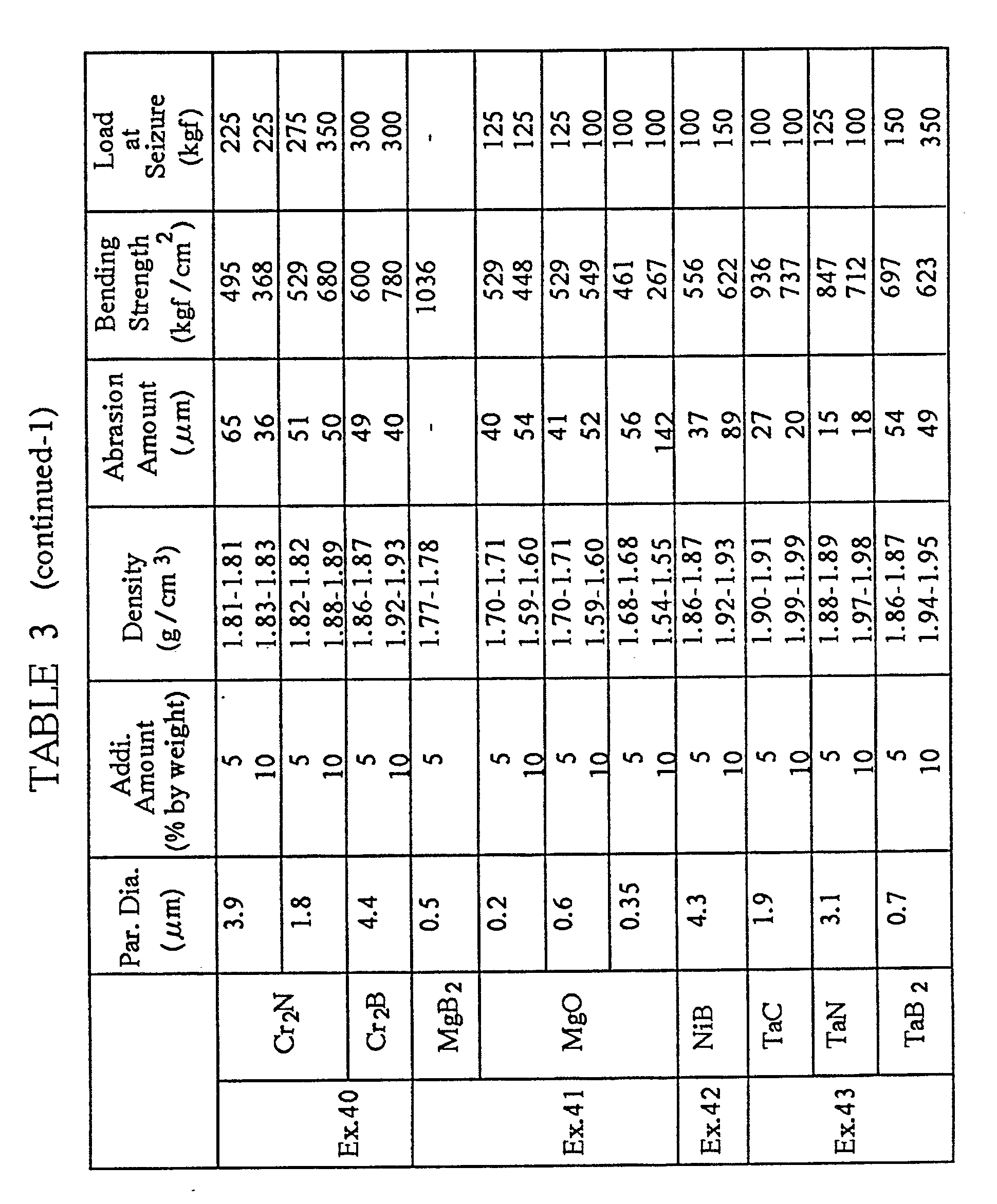
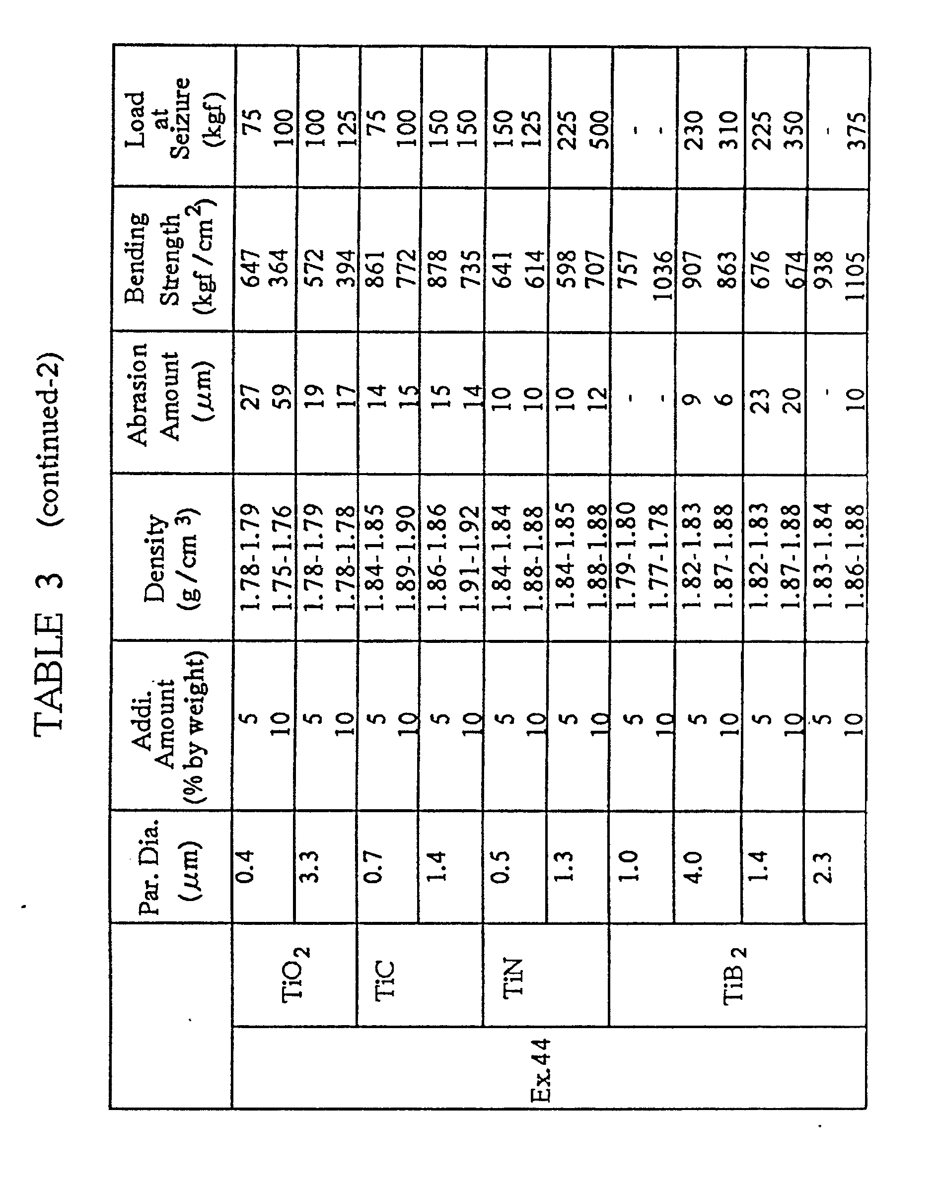

- The following raw materials were prepared: 28.6 % by weight of infusible preliminarily carbonized carbonaceous fiber having the fiber diameter of 15 µm and the fiber length of 0.5 mm and comprising the coal optically isotropic pitch identical to the one employed in Example 1, 66.5 % by weight of self-sintering carbonaceous powder comprising the mesocarbon microbeads having the average particle diameter of 6 µm identical to the one employed in Example 1, and 5 % by weight of Ti powder having the average particle diameter of 8 µm. The above-mentioned raw materials were mixed uniformly with a mixer, and thereafter a resulting mixture was molded into a composite body having a test piece shape in the size of o 50 x 10 mm under the molding pressure of 2 ton/cm² identical to that of Example 1.
- Then, the composite body was burned by increasing the temperature from an ordinary temperature to 1000 °C at the rate of 150 °C/hour, then by maintaining the temperature of 1000 °C for 1 hour, and thereafter by decreasing the temperature fron 1000 °C to an ordinary temperature under an ordinary pressure in a nitrogen gas atmosphere. A first sintered body was thus prepared. After measuring the density of the first sintered body, the first sintered body was further burned by increasing the temperature from an ordinary temperature to 1700 °C at the rate of 500 °C/hour, then by maintaining the temperature of 1700 °C for 20 minutes, and thereafter by decreasing the temperature fron 1700 °C to an ordinary temperature under an ordinary pressure in a nitrogen gas atmosphere. A second sintered body, namely a sliding member of Example 47, was thus prepared.
- A composite body and a first sintered body of Exanple 48 was prepared by employing the same raw materials and in the same manner as described in Example 47 except that Ni powder having the average particle diameter of 4 µm was employed. After measuring the density of the first sintered body thus prepared, the first sintered body was further burned by increasing the temperature from an ordinary temperature to 1300 °C at the rate of 500 °C/hour, then by maintaining the temperature of 1300 °C for 20 minutes, and thereafter by decreasing the temperature from 1300 °C to an ordinary temperature under an ordinary pressure in a nitrogen gas atmosphere. A second sintered body, namely a sliding member of Example 48, was thus prepared.
-
- The densities of the thus prepared sliding members of Examples 47 and 48 were measured first. Then, their bending strength were measured by carrying out a bending strength test identical to the one described in Evaluation 11. The results of the measurement are summarized in Table 4. The results of the measurement on the densities of the first sintered bodies of Examples 47 and 48 are also set forth in Table 4. In addition, the measurements on the abrasion amounts and the loads at seizure of the sliding members of Examples 47 and 48 are set forth in Table 5.
Table 4 Density (g/cm³), 1st Sintered Body Density (g/cm³), 2nd Sintered Body Bending Strength (kgf/cm²), 2nd Sintered Body Ex. 47 1.67 1.79 775 Ex. 48 1.69 1.76 810 Table 5 Par. Dia. (µm) Addi. Amount (% by weight) Density (g/cm³) Abrasion Amount (µm) Bending Strength (kgf/cm²) Load at Seizure (kgf) Ex. 47 Ti 8 5 1.79 17 775 75 Ex. 48 Ni 4 5 1.76 14 810 125 - It is apparent from Tables 4 and 5 that the bending strength of the sliding member of Example 47 was as high as those of the sliding members of Example 44 in which the inorganic titanium compound was added as the inorganic powder, and that the bending strength of the sliding member of Example 48 exceeded the bending strength exhibited by the sliding member of Example 42 in which nickel boride (NiB) was added as the inorganic powder. Thus, it is expected that the sliding members of Example 47 and 48 can have more favorable properties than those of the conventional sliding member made from the carbon-carbon composite material.
- Having now fully described the present invention, it will be apparent to one of ordinary skill in the art that many changes and modifications can be made thereto without departing from the spirit or scope of the present invention as set forth herein.
Claims (51)
a sintered body obtained by sintering a composite body comprising:
preliminarily carbonized carbonaceous fiber;
inorganic powder or inorganic fiber; and
self-sintering carbonaceous powder with said preliminarily carbonized carbonaceous fiber and said inorganic powder or said inorganic fiber buried therein.
and pulverized low temperature calcined coke powder.
a sintered body obtained by sintering a composite body comprising:
preliminarily carbonized carbonaceous fiber;
boron compound powder; and
self-sintering carbonaceous powder with said preliminarily carbonized carbonaceous fiber and said boron compound powder buried therein.
Applications Claiming Priority (4)
| Application Number | Priority Date | Filing Date | Title |
|---|---|---|---|
| JP16024189 | 1989-06-22 | ||
| JP160241/89 | 1989-06-22 | ||
| JP341883/89 | 1989-12-29 | ||
| JP34188389 | 1989-12-29 |
Publications (2)
| Publication Number | Publication Date |
|---|---|
| EP0404571A1 true EP0404571A1 (en) | 1990-12-27 |
| EP0404571B1 EP0404571B1 (en) | 1996-11-27 |
Family
ID=26486801
Family Applications (1)
| Application Number | Title | Priority Date | Filing Date |
|---|---|---|---|
| EP19900306795 Expired - Lifetime EP0404571B1 (en) | 1989-06-22 | 1990-06-21 | Sliding member |
Country Status (3)
| Country | Link |
|---|---|
| EP (1) | EP0404571B1 (en) |
| JP (1) | JPH068216B2 (en) |
| DE (1) | DE69029227T2 (en) |
Cited By (11)
| Publication number | Priority date | Publication date | Assignee | Title |
|---|---|---|---|---|
| EP0507564A2 (en) * | 1991-04-05 | 1992-10-07 | Toyota Jidosha Kabushiki Kaisha | Carbon composite material |
| WO2003008821A1 (en) * | 2001-07-18 | 2003-01-30 | Tea Gmbh | System of sliding surfaces comprising one carbon-based sliding element |
| GB2395721A (en) * | 2002-10-14 | 2004-06-02 | Miba Frictec Gmbh | A friction lining |
| WO2005102962A1 (en) * | 2004-04-01 | 2005-11-03 | Honeywell International Inc. | Titanium carbide as a friction and wear modifier in friction materials |
| US7575799B2 (en) | 2005-03-16 | 2009-08-18 | Honeywell International Inc. | Carbon fiber containing ceramic particles |
| EP2253604A1 (en) | 2009-05-13 | 2010-11-24 | Messier Bugatti | Part made from a C/C composite material and method for manufacturing same |
| WO2012063003A1 (en) | 2010-11-10 | 2012-05-18 | Messier-Bugatti-Dowty | Method for the production of a friction part comprising a c/c composite material |
| CN112358905A (en) * | 2020-11-09 | 2021-02-12 | 扬州工业职业技术学院 | Ternary boride solid lubrication gradient coating and preparation method thereof |
| WO2022162319A1 (en) | 2021-01-29 | 2022-08-04 | Safran Landing Systems | Method for drying an impregnated blank and associated manufacturing method, system and assembly |
| FR3129294A1 (en) | 2021-11-25 | 2023-05-26 | Safran Landing Systems | Diffuser to diffuse a flow of gas within a stack of blanks and associated assemblies |
| FR3129468A1 (en) | 2021-11-25 | 2023-05-26 | Safran Landing Systems | DEVICE FOR DRYING BLANKS AND ASSOCIATED SYSTEM AND ASSEMBLY AND METHOD |
Families Citing this family (4)
| Publication number | Priority date | Publication date | Assignee | Title |
|---|---|---|---|---|
| JP3154008B2 (en) * | 1991-10-29 | 2001-04-09 | 三菱瓦斯化学株式会社 | Manufacturing method of friction material |
| JPH05179232A (en) * | 1991-12-26 | 1993-07-20 | Toshiba Tungaloy Co Ltd | Sintered metallic friction material for brake |
| US6255234B1 (en) * | 1997-01-30 | 2001-07-03 | Hitco Carbon Composites, Inc. | Ultra low friction carbon/carbon composites for extreme temperature applications |
| DE10250035A1 (en) * | 2002-10-27 | 2004-05-13 | Viking Gmbh | Safety clutch for a self-propelled lawnmower |
Citations (1)
| Publication number | Priority date | Publication date | Assignee | Title |
|---|---|---|---|---|
| DE2165029A1 (en) * | 1970-12-29 | 1972-08-31 | Kureha Chemical Ind Co Ltd | Process for the production of carbon molded parts |
Family Cites Families (4)
| Publication number | Priority date | Publication date | Assignee | Title |
|---|---|---|---|---|
| JPS61111963A (en) * | 1984-11-05 | 1986-05-30 | 出光興産株式会社 | Manufacture of carbon formed body |
| JP2635634B2 (en) * | 1987-11-30 | 1997-07-30 | イビデン株式会社 | Method for producing carbon fiber reinforced carbon material |
| JPH01145371A (en) * | 1987-11-30 | 1989-06-07 | Agency Of Ind Science & Technol | Highly wear-resistant c-b4c-based sliding member |
| JPH01239060A (en) * | 1988-03-18 | 1989-09-25 | Nkk Corp | Production of carbon fiber reinforced carbon composite material |
-
1990
- 1990-06-21 JP JP2163388A patent/JPH068216B2/en not_active Expired - Lifetime
- 1990-06-21 DE DE1990629227 patent/DE69029227T2/en not_active Expired - Fee Related
- 1990-06-21 EP EP19900306795 patent/EP0404571B1/en not_active Expired - Lifetime
Patent Citations (1)
| Publication number | Priority date | Publication date | Assignee | Title |
|---|---|---|---|---|
| DE2165029A1 (en) * | 1970-12-29 | 1972-08-31 | Kureha Chemical Ind Co Ltd | Process for the production of carbon molded parts |
Non-Patent Citations (4)
| Title |
|---|
| CHEMICAL ABSTRACTS, vol. 106, no. 14, April 1987, page 308, abstract no. 106975u, Columbus, Ohio, US; & JP-A-61 215 256 (KOMATSU, LTD) 25-09-1986 * |
| CHEMICAL ABSTRACTS, vol. 108, no. 14, April 1988, page 342, abstract no. 117717d, Columbus, Ohio, US; & JP-A-62 252 370 (ALLIED CORP.) 04-11-1987 * |
| CHEMICAL ABSTRACTS, vol. 108, no. 26, June 1988, page 260, abstract no. 225867m, Columbus, Ohio, US; & JP-A-63 60 173 (SUMITOMO ELECTRIC INDUSTRIES, LTD) 16-03-1988 * |
| CHEMICAL ABSTRACTS, vol. 110, no. 9, 1st May 1989, page 330, abstract no. 159377q, Columbus, Ohio, US; & JP-A-63 265 863 (KAWASAKI STEEL CORP.) 02-11-1988 * |
Cited By (18)
| Publication number | Priority date | Publication date | Assignee | Title |
|---|---|---|---|---|
| EP0507564A3 (en) * | 1991-04-05 | 1994-04-13 | Toyota Motor Co Ltd | |
| EP0507564A2 (en) * | 1991-04-05 | 1992-10-07 | Toyota Jidosha Kabushiki Kaisha | Carbon composite material |
| WO2003008821A1 (en) * | 2001-07-18 | 2003-01-30 | Tea Gmbh | System of sliding surfaces comprising one carbon-based sliding element |
| GB2395721A (en) * | 2002-10-14 | 2004-06-02 | Miba Frictec Gmbh | A friction lining |
| GB2395721B (en) * | 2002-10-14 | 2007-01-24 | Miba Frictec Gmbh | A friction lining |
| WO2005102962A1 (en) * | 2004-04-01 | 2005-11-03 | Honeywell International Inc. | Titanium carbide as a friction and wear modifier in friction materials |
| US8858846B2 (en) | 2004-04-01 | 2014-10-14 | Honeywell International Inc. | Titanium carbide as a friction and wear modifier in friction materials |
| US7575799B2 (en) | 2005-03-16 | 2009-08-18 | Honeywell International Inc. | Carbon fiber containing ceramic particles |
| US8871044B2 (en) | 2009-05-13 | 2014-10-28 | Messier-Bugatti-Dowty | Part based on C/C composite material, and a method of fabricating it |
| EP2253604A1 (en) | 2009-05-13 | 2010-11-24 | Messier Bugatti | Part made from a C/C composite material and method for manufacturing same |
| WO2012063003A1 (en) | 2010-11-10 | 2012-05-18 | Messier-Bugatti-Dowty | Method for the production of a friction part comprising a c/c composite material |
| CN112358905A (en) * | 2020-11-09 | 2021-02-12 | 扬州工业职业技术学院 | Ternary boride solid lubrication gradient coating and preparation method thereof |
| CN112358905B (en) * | 2020-11-09 | 2022-05-27 | 扬州工业职业技术学院 | Ternary boride solid lubrication gradient coating and preparation method thereof |
| WO2022162319A1 (en) | 2021-01-29 | 2022-08-04 | Safran Landing Systems | Method for drying an impregnated blank and associated manufacturing method, system and assembly |
| FR3119389A1 (en) | 2021-01-29 | 2022-08-05 | Safran Landing Systems | METHOD FOR DRYING AN IMPREGNATED BACKGROUND AND METHOD FOR MANUFACTURING AND ASSOCIATED SYSTEM AND ASSEMBLY |
| FR3129294A1 (en) | 2021-11-25 | 2023-05-26 | Safran Landing Systems | Diffuser to diffuse a flow of gas within a stack of blanks and associated assemblies |
| FR3129468A1 (en) | 2021-11-25 | 2023-05-26 | Safran Landing Systems | DEVICE FOR DRYING BLANKS AND ASSOCIATED SYSTEM AND ASSEMBLY AND METHOD |
| WO2023094780A1 (en) | 2021-11-25 | 2023-06-01 | Safran Landing Systems | Diffuser for diffusing a gas flow within a stack of blanks and associated assemblies |
Also Published As
| Publication number | Publication date |
|---|---|
| DE69029227T2 (en) | 1997-05-22 |
| DE69029227D1 (en) | 1997-01-09 |
| JPH03237062A (en) | 1991-10-22 |
| EP0404571B1 (en) | 1996-11-27 |
| JPH068216B2 (en) | 1994-02-02 |
Similar Documents
| Publication | Publication Date | Title |
|---|---|---|
| EP0404571B1 (en) | Sliding member | |
| US6703117B2 (en) | Friction body or sliding body formed from composite materials reinforced with fiber bundles and containing a ceramics matrix and process for the production of a friction or sliding body | |
| US6838162B1 (en) | Fiber-bundle-reinforced composite material having a ceramic matrix, method for manufacturing a composite material and method for manufacturing elements formed of a composite material | |
| DE10131769C5 (en) | Brake system with composite brake disc | |
| US20040097360A1 (en) | Fiber-reinforced composite ceramic, fabrication method and lining material, armor, reflective surface and component having the composite ceramic | |
| JPH10503744A (en) | Self-sintering silicon carbide / carbon composite | |
| US5169718A (en) | Sliding member | |
| US7364794B2 (en) | Oxidation resistant carbon fiber reinforced carbon composite material and process for producing the same | |
| EP1323685B1 (en) | Method of production of shaped bodies out of fibre reinforced ceramic materials | |
| US5202293A (en) | Carbon fiber reinforced carbon | |
| EP0507564A2 (en) | Carbon composite material | |
| EP1489331B1 (en) | Metal- infiltrated, fiber-reinforced porous carbon friction body | |
| US4720349A (en) | Sliding member of graphite-metal borides | |
| JPH0238365A (en) | Complex sliding member of high-temperature-reisistant and high-strength graphite base | |
| EP0379328B1 (en) | Carbon fiber reinforced carbon | |
| JPH0478374A (en) | Shift fork for transmission | |
| JPH05306166A (en) | Carbon composite material | |
| JP2000052461A (en) | Kiln tool excellent in processability | |
| JPH0476298A (en) | Vane pump | |
| JPH07115958B2 (en) | Carbon fiber reinforced carbon composite material with high friction coefficient | |
| JPH0476251A (en) | Cylinder block | |
| JPH04310567A (en) | Carbon fiber reinforced carbon composite material having low coefficient of friction | |
| JPH0476226A (en) | Float bearing for turbochrger | |
| JPH0476256A (en) | Piston for internal combustion engine | |
| JPH0475819A (en) | Composite electrode for electric discharge machining |
Legal Events
| Date | Code | Title | Description |
|---|---|---|---|
| PUAI | Public reference made under article 153(3) epc to a published international application that has entered the european phase |
Free format text: ORIGINAL CODE: 0009012 |
|
| 17P | Request for examination filed |
Effective date: 19900629 |
|
| AK | Designated contracting states |
Kind code of ref document: A1 Designated state(s): DE FR GB |
|
| 17Q | First examination report despatched |
Effective date: 19930819 |
|
| GRAG | Despatch of communication of intention to grant |
Free format text: ORIGINAL CODE: EPIDOS AGRA |
|
| GRAH | Despatch of communication of intention to grant a patent |
Free format text: ORIGINAL CODE: EPIDOS IGRA |
|
| GRAH | Despatch of communication of intention to grant a patent |
Free format text: ORIGINAL CODE: EPIDOS IGRA |
|
| GRAA | (expected) grant |
Free format text: ORIGINAL CODE: 0009210 |
|
| RIN1 | Information on inventor provided before grant (corrected) |
Inventor name: NAKATANI, SATORU, C/O OSAKA GAS COMPANY LTD. Inventor name: NAKAGAWA, YOSHITERU, C/O OSAKA GAS COMPANY LTD. Inventor name: MICHIOKA, HIROHUMI Inventor name: FUWA, YOSHIO Inventor name: TSUCHIYA, SHOICHI Inventor name: OKAMOTO, MAMORU Inventor name: MIURA, HIROHISA |
|
| AK | Designated contracting states |
Kind code of ref document: B1 Designated state(s): DE FR GB |
|
| ET | Fr: translation filed | ||
| REF | Corresponds to: |
Ref document number: 69029227 Country of ref document: DE Date of ref document: 19970109 |
|
| PLBE | No opposition filed within time limit |
Free format text: ORIGINAL CODE: 0009261 |
|
| STAA | Information on the status of an ep patent application or granted ep patent |
Free format text: STATUS: NO OPPOSITION FILED WITHIN TIME LIMIT |
|
| 26N | No opposition filed | ||
| REG | Reference to a national code |
Ref country code: GB Ref legal event code: 746 Effective date: 19991109 |
|
| REG | Reference to a national code |
Ref country code: FR Ref legal event code: D6 |
|
| PGFP | Annual fee paid to national office [announced via postgrant information from national office to epo] |
Ref country code: FR Payment date: 20000612 Year of fee payment: 11 |
|
| PGFP | Annual fee paid to national office [announced via postgrant information from national office to epo] |
Ref country code: DE Payment date: 20000619 Year of fee payment: 11 |
|
| PGFP | Annual fee paid to national office [announced via postgrant information from national office to epo] |
Ref country code: GB Payment date: 20000621 Year of fee payment: 11 |
|
| PG25 | Lapsed in a contracting state [announced via postgrant information from national office to epo] |
Ref country code: GB Free format text: LAPSE BECAUSE OF NON-PAYMENT OF DUE FEES Effective date: 20010621 |
|
| GBPC | Gb: european patent ceased through non-payment of renewal fee |
Effective date: 20010621 |
|
| PG25 | Lapsed in a contracting state [announced via postgrant information from national office to epo] |
Ref country code: FR Free format text: LAPSE BECAUSE OF NON-PAYMENT OF DUE FEES Effective date: 20020228 |
|
| PG25 | Lapsed in a contracting state [announced via postgrant information from national office to epo] |
Ref country code: DE Free format text: LAPSE BECAUSE OF NON-PAYMENT OF DUE FEES Effective date: 20020403 |