EP0404052B1 - Polarisationserhaltender Koppler - Google Patents
Polarisationserhaltender Koppler Download PDFInfo
- Publication number
- EP0404052B1 EP0404052B1 EP90111547A EP90111547A EP0404052B1 EP 0404052 B1 EP0404052 B1 EP 0404052B1 EP 90111547 A EP90111547 A EP 90111547A EP 90111547 A EP90111547 A EP 90111547A EP 0404052 B1 EP0404052 B1 EP 0404052B1
- Authority
- EP
- European Patent Office
- Prior art keywords
- polarization
- light
- fiber
- polarization maintaining
- fibers
- Prior art date
- Legal status (The legal status is an assumption and is not a legal conclusion. Google has not performed a legal analysis and makes no representation as to the accuracy of the status listed.)
- Expired - Lifetime
Links
Images


Classifications
-
- G—PHYSICS
- G02—OPTICS
- G02B—OPTICAL ELEMENTS, SYSTEMS OR APPARATUS
- G02B6/00—Light guides; Structural details of arrangements comprising light guides and other optical elements, e.g. couplings
- G02B6/24—Coupling light guides
- G02B6/26—Optical coupling means
- G02B6/27—Optical coupling means with polarisation selective and adjusting means
- G02B6/2746—Optical coupling means with polarisation selective and adjusting means comprising non-reciprocal devices, e.g. isolators, FRM, circulators, quasi-isolators
-
- G—PHYSICS
- G02—OPTICS
- G02B—OPTICAL ELEMENTS, SYSTEMS OR APPARATUS
- G02B6/00—Light guides; Structural details of arrangements comprising light guides and other optical elements, e.g. couplings
- G02B6/24—Coupling light guides
- G02B6/26—Optical coupling means
- G02B6/27—Optical coupling means with polarisation selective and adjusting means
- G02B6/2726—Optical coupling means with polarisation selective and adjusting means in or on light guides, e.g. polarisation means assembled in a light guide
- G02B6/274—Optical coupling means with polarisation selective and adjusting means in or on light guides, e.g. polarisation means assembled in a light guide based on light guide birefringence, e.g. due to coupling between light guides
-
- G—PHYSICS
- G02—OPTICS
- G02B—OPTICAL ELEMENTS, SYSTEMS OR APPARATUS
- G02B6/00—Light guides; Structural details of arrangements comprising light guides and other optical elements, e.g. couplings
- G02B6/24—Coupling light guides
- G02B6/26—Optical coupling means
- G02B6/28—Optical coupling means having data bus means, i.e. plural waveguides interconnected and providing an inherently bidirectional system by mixing and splitting signals
- G02B6/293—Optical coupling means having data bus means, i.e. plural waveguides interconnected and providing an inherently bidirectional system by mixing and splitting signals with wavelength selective means
- G02B6/29331—Optical coupling means having data bus means, i.e. plural waveguides interconnected and providing an inherently bidirectional system by mixing and splitting signals with wavelength selective means operating by evanescent wave coupling
- G02B6/29332—Wavelength selective couplers, i.e. based on evanescent coupling between light guides, e.g. fused fibre couplers with transverse coupling between fibres having different propagation constant wavelength dependency
-
- G—PHYSICS
- G02—OPTICS
- G02B—OPTICAL ELEMENTS, SYSTEMS OR APPARATUS
- G02B6/00—Light guides; Structural details of arrangements comprising light guides and other optical elements, e.g. couplings
- G02B6/24—Coupling light guides
- G02B6/42—Coupling light guides with opto-electronic elements
- G02B6/4201—Packages, e.g. shape, construction, internal or external details
- G02B6/4246—Bidirectionally operating package structures
Definitions
- the present invention relates to a polarization coupler for introducing light from two laser diodes into a single optical fibre or the like and also to a process of manufacturing such a polarization coupler.
- the document Optical Fibre Communication Conference and 6th International Conference on Integrated Optics and Optical Communication", Technical Digest, Paper TUJ5, page 80 by W.L. Emkey et al, "Single-Mode Polarization-Selective Coupler Using For Fibre Lenses" describes a polarization selective coupler.
- the device comprises a first polarization maintaining fibre and a second polarization maintaining fibre having a polarization plane perpendicular to the polarization plane of the first polarization maintaining fibre. Said device is particularly designed to combine the light output from the two polarization maintaining fibres into a single output fibre.
- the device achieves a minimization of changes in coupling loss due to relative translational misalignments of the axis of the two polarization maintaining fibres.
- the polarization selective coupler operates as a polarization selective splitter splitting light output from the single fibre into the two polarization maintaining fibres with orthogonal polarisation planes.
- the rutile crystal interposed between the two polarization maintaining fibres and the output fibre merely combines light from the two polarization maintaining fibres.
- a polarization coupler having first and second polarization maintaining fibres disposed adjacent to eachother, having their geometrical axis parallel to each other and having input light transmitted therethrough with orthogonal polarizations in the two fibres, a third fibre having a geometrical axis disposed on an extension line of the geometrical axis of the first fibre and birefringent plate, i.e. a rutile crystal disposed between the first and second fibres and the third fibre such that the ordinary ray of light originating from the first fibre and the extraordinary ray of light originating from the second fibre are both transmitted to the third fibre.
- a polarization coupler is used to introduce in a highly reliable system of the type mentioned beams of polarized light from two light sources (linearly polarized or elliptically polarized light approximating linearly polarized light) into a common optical fibre.
- part of the optical output is sometimes split and power of the thus split light is monitored in order to watch, for example, deterioration of the light source with the passage of time.
- a polarization coupler suitable for such monitoring is thus demanded.
- a polarization coupler which includes a polarizing prism and a beam splitter having a branching ratio free from polarization dependency is known as a polarization coupler which allows such monitoring as described above.
- an optical transmitter which includes a polarization coupler of the type just mentioned, beams of light emitted from, for example, two laser diodes and having polarization planes perpendicular to each other are collimated by a lens and introduced into the same light path by way of a polarizing prism so that they are introduced into an optical fiber by means of a beam splitter, having a branching ratio free from polarization dependency, and a condensing lens. Monitoring for the light intensity is effected using light split by the beam splitter.
- a conventional polarization coupler is constituted using a polarizing prism for the composition of beams of light (linearly polarized light in ordinary cases) from two light sources while using a beam splitter having a branching ratio free from polarization dependency for the monitoring, and besides requiring a lens for forming a parallel light beam system in this manner, this imposes a limitation on the miniaturization of the device.
- a polarization coupler is provided which is high in operability in production and is suitable for miniaturization. Further, since a possible increase in loss arising from formation of a parallel light beam system is eliminated, a polarization coupler is provided, which is low in loss.
- a polarization coupler having the features a) to i) of claim 1, when the first and second polarization maintaining fibres 2 and 4 are connected to two light sources, main signal light can be extracted from the fifth polarization maintaining fibre 14 while light for monitoring can be extracted from the sixth polarization maintaining fibre 16.
- the basic construction described in claim 1 can be readily realized by mounting said first to sixth polarization maintaining fibres 2,4,6,12,14,16 and said rotator 8 and said birefringent plate 10 on a substrate.
- the loss of light by the polarization coupler can be restricted to low values.
- the separation angle between an ordinary ray of light and extraordinary ray of light with respect to a unit-thickness of the birefringent plate 10 or alternatively the thickness of the birefringent plate 10 with respect to a unit separation angle between an ordinary ray of light and an extraordinary ray of light can be reduced and consequently the loss of the polarization coupler can be restricted to small values.
- the birefringent fibre may be of the stress inducing type which has a cross-section in which a pair of stress applying portions are provided in the cladding in a symmetrical relationship on opposite sides of the core.
- said birefringent fibre may be of the stress inducing type which has a cross-section in which an elliptical stress applying portion is provided in the cladding round the core.
- the predetermined angle (the angle of rotation of light by the rotator 8) is set such that for given orthogonal input light polarization directions the power of the extraordinary ray of light which is transmitted through said fifth polarization maintaining fibre is higher than the power of the ordinary ray of light which is transmitted through said fourth polarization maintaining fibre and the power of the ordinary ray of light which is transmitted through said fifth polarization maintaining fibre is higher than the power of the extraordinary ray of light which is transmitted through said sixth polarization maintaining fibre.
- the setting of the predetermined angle may be effected by setting the orientation of the optical axis of a half-wave plate which is employed as the rotator 8.
- the setting of the predetermined angle may be realized by the setting of a predetermined magnetic field which is applied to a Faraday rotator employed as the rotator 8.
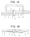
- a polarization coupler according to the present invention wherein various components are secured to a substrate 18 made of quartz or the like and having a flat surface thereon.
- first to sixth polarization maintaining fibers 2, 4, 6, 12, 14 and 16 are secured to the substrate 18 in this manner, it is easy to position the geometrical center axes of the individual fibers in the same plane.
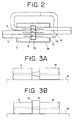
- a function of the polarization coupler will be described subsequently with reference to Fig. 2.
- beams of light are introduced into the rotator 8 from the first and second fibers 2 and 4, then the polarization planes of them are rotated by a predetermined angle in the same direction, and then the beams of light having the thus rotated polarization planes are introduced into the birefringent plate 10. If a beam of light having a polarization plane which extends neither perpendicularly nor in parallel to the plane of Fig. 2 is introduced into the birefringent plate 10, then it is split into an ordinary ray of light and an extraordinary ray of light, and the thus split rays of light are normally transmitted in different directions such that the ordinary ray of light advances straightforwardly.
- the ordinary rays of light from the birefringent plate 10 can be introduced into the fourth and fifth fibers 12 and 14 disposed in a coaxial relationship with the first and second fibers 2 and 4, respectively.
- the optical axis of the birefringent plate 10 is set in a specific manner, then an extraordinary ray of light can be transmitted in a direction inclined by a predetermined angle with respect to the geometrical axis of each fiber on a plane including the geometrical axes.
- the thickness of the birefringent plate 10 is set in a specific manner, then the extraordinary ray of light from the first fiber 2 can be introduced into the fifth fiber 14 while the extraordinary ray of light from the second fiber 4 can be introduced into the sixth fiber 16.
- the ordinary ray of light introduced into the fourth fiber 12 is then introduced into the third fiber 6 while maintaining its polarization plane, whereafter it passes through the rotator 8 and then through the birefringent plate 10 and is then introduced into the sixth fiber 16. Accordingly, light introduced into the fifth fiber 14 can be extracted as a main signal output while light introduced into the sixth fiber 16 can be extracted for monitoring.
- the angle of rotation of the polarization plane (the aforementioned predetermined angle) by the rotator 8 is set such that, for example, 5 % of light transmitted by way of the first fiber 2 (first input light) may be introduced as an ordinary ray of light into the fourth fiber 12, ignoring loss, the remaining 95 % of the light is introduced as an extraordinary ray of light into the fifth fiber 14.
- the polarization plane of the light transmitted by way of the second fiber 4 (second input light) extends perpendicularly to the polarization plane of the first input light, 5 % of the second input light is introduced as an extraordinary ray of light into the sixth fiber 16 while the remaining 95 % is introduced as an ordinary ray of light into the fifth fiber 14.
- the ordinary ray of light originating from the first input light is 4.75 % of the original first input light because second 5 % is removed as an extraordinary ray of light from 5 % of the original fist input light. Since the difference is very small, however, it does not make any essential matter in monitoring powers of the first and second input light.
- the first, second and third fibers 2, 4 and 6 are held in a closely contacting relationship with the rotator 8 which is in turn held in a closely contacting relationship with the birefringent plate 10 while the fourth, fifth and sixth fibers 12, 14 and 16 are held in a closely contacting relationship with the birefringent plate 10.
- An effect achieved by such construction will be described below with reference to Figs. 3A and 3B. Where there is a spacing between the first and fourth fibers 2 and 12 as shown in Fig.
- the first and third fibers 2 and 6 are held in a closely contacting relationship with the second fiber 4 while the fourth and sixth fibers 12 and 16 are held in a closely contacting relationship with the fifth fiber 14 as shown in Fig. 2.
- the geometrical center axes of the individual fibers can be disposed proximately to each other, if the separation angle of the birefringent plate 10 between an ordinary ray of light and an extraordinary ray of light is fixed, then the thickness of the birefringent plate 10 can be reduced, but on the contrary if the thickness of the birefringent plate 10 is fixed, then the separation angle between an ordinary ray of light and an extraordinary ray of light can be reduced. Consequently, the polarization coupler can be reduced in loss.
- the first to sixth fibers 2, 4, 6, 12, 14 and 16 may each be formed from a birefringent fiber which has different propagation coefficients for light of a HE x mode and for light of a HE y mode.
- the HE x mode is that one of HE11 modes, which can be transmitted through a single mode fiber, which has an electric field in an x-axis direction perpendicular to the transmitting direction of light
- the HE y mode is that one of the HE11 modes which has an electric field in a y-axis direction perpendicular to the transmitting direction of light and also to the x-axis direction.
- the first to fourth fibers 2, 4, 6 and 12 are required to allow transmission therethrough only of a polarized light component having a predetermined polarization plane while the fifth and sixth fibers 14 and 16 are required to allow transmission therethrough of two polarized light components having perpendicular polarization planes
- the first to fourth fibers 2, 4, 6 and 12 may otherwise be formed each from a polarization maintaining fiber which is designed such that it may present significantly different transmission losses with light of the HE x mode and the HE y mode, or in other words, which is designed such that light of only one mode may be transmitted therein.
- birefringent fiber An example of construction of a birefringent fiber will be described with reference to Fig. 4 in which construction of an end face of the first fiber 2 is shown by way of an example.
- the birefringent fiber shown is of the stress inducing type wherein it has, as viewed in section, a pair of stress applying portions 2c and 2d provided in the cladding 2b in a symmetrical relationship on opposite sides of the core 2a.
- the stress applying portions 2c and 2d are formed from a material having a different coefficient of linear expansion from that of the cladding 2b.
- the core 2a since the core 2a is provided with different stresses in the x-axis direction in which the core 2a and the stress applying portions 2c and 2d extend and the y-axis direction perpendicular to the x-axis direction, the core 2a has some anisotropy in refractive index, and consequently, the birefringent fiber can maintain the polarization plane of light of a particular mode.
- linearly polarized light having a polarization plane parallel to the x-axis or linearly polarized light having another polarization plane parallel to the y-axis can be transmitted in the birefringent fiber without changing the polarization condition.
- a stress applying portion 2e having a substantially elliptical section is provided in the cladding 2b around the core 2a such that the major axis of the ellipse of the section thereof may be positioned on the x-axis while the minor axis is positioned on the y-axis.
- the core 2a is provided with some birefringence and consequently can maintain the polarization plane of light of a particular mode.
- a half-wave plate may be employed for the rotator 8.
- setting of the angle of rotation can be achieved by setting of the orientation of the optical axis of the half-wave plate.
- the rotator 8 may otherwise be constituted from a Faraday rotator to which a predetermined magnetic field is applied.
- setting of the angle of rotation can be achieved by setting of the predetermined magnetic field.
- the branching ratio of light for monitoring with respect to the main signal output can be adjusted readily by arbitrarily setting the angle of rotation in this manner.
- the angle of rotation of light by the rotator 8 is preferably set such that for given orthogonal input light polarization directions the power of the extraordinary ray of light which is transmitted in the fifth fiber 14 is higher than the power of the ordinary ray of light which is transmitted in the fourth fiber 12 while the power of the extraordinary ray of light which is transmitted in the fifth fiber 14 is higher than the power of the ordinary ray of light which is transmitted in the sixth fiber 16.
- a second mother fiber 22 which is to make the second and fifth fibers 4 and 14
- a third mother fiber 24 which is to make the third and sixth fibers 6 and 16 are fixed to a substrate 18, in the form of a flat plate made of quartz glass or the like, as shown in Fig. 6A using, for example, a bonding agent. They may otherwise be fixed by soldering to a substrate which is plated in advance with gold on the fixing face thereof.
- the second mother fiber 22 is held in a closely contacting relationship with the first and third mother fibers 20 and 24 on the substrate 18.
- the mother fibers 20, 22 and 24 have maintained polarization planes (polarization planes of linearly polarized light transmitted while being maintained) which extend in parallel or perpendicularly to each other.
- the first mother fiber 20 is disposed such that the x-axis thereof in Fig. 4 extends perpendicularly to the fixing surface of the substrate while the y-axis extends in parallel to the fixing surface
- the second and third mother fibers 22 and 24 are disposed such that the x-axes thereof extend in parallel to the substrate fixing surface while the y-axes extend perpendicularly to the substrate fixing surface.
- the mother fibers 20, 22 and 24 secured to the substrate 18 are cut in a predetermined cutting width using a cutting saw or the like such that the opposing cut faces thereof may be positioned in the same plane as shown in FIG. 6B, thereby dividing the first mother fiber 20 into first and fourth fibers 2 and 12, the second mother fiber 22 into second and fifth fibers 4 and 14 and the third mother fiber 24 into third and sixth fibers 6 and 16.
- a groove or slit 26 may be formed on the substrate 18 in a shape in accordance with a driving radius of the cutting saw due to a dispersion or the like in an operation for the production, but there will be no trouble with such groove 26.
- a rotator 8 and a birefringent plate 10 which are integrated in advance with each other using an optical bonding agent or the like are inserted between the first, second and third fibers 2, 4 and 6 and the fourth, fifth and sixth fibers 12, 14 and 16 and are secured to the latter by means of an optical bonding agent or the like as seen in Fig. 6C.
- the third fiber 6 and the fourth fiber 12 are adhered to each other, for example, by fusion such that the maintaining polarization planes thereof may extend in parallel or perpendicularly to each other.
- Confirmation of a maintaining polarization plane of a fiber can be effected by irradiating a beam of visible laser upon the fiber sidewardly to confirm a stress applying portion of the fiber.
- FIG. 7 there is shown construction of a main portion of an optical transmitter to which a polarization coupler of the present invention is applied.
- Reference numeral 28 denotes a laser diode connected to the first fiber 2, 30 another laser diode connected to the second fiber 4, and 32 a monitoring photodiode connected to the sixth fiber 16.
- light from either of the laser diodes 28 and 30 can be outputted by way of the fifth fiber 14. Accordingly, the reliability of the optical transmitter by the duplicating of the light source can be improved.
- optical outputs of the laser diodes 28 and 30 can be split at substantially equal branching ratios from a main signal route to detect powers thereof, a deterioration of an operating laser diode with the passage of time can be watched on an on-line basis.
- the third and fourth fibers 6 and 12 are produced from different mother fibers, the first and third mother fibers may otherwise be made common to omit connection of the third and fourth fibers 6 and 12 by fusion.
Landscapes
- Physics & Mathematics (AREA)
- General Physics & Mathematics (AREA)
- Optics & Photonics (AREA)
- Optical Couplings Of Light Guides (AREA)
- Optical Modulation, Optical Deflection, Nonlinear Optics, Optical Demodulation, Optical Logic Elements (AREA)
Claims (11)
- Polarisationskoppler mita) einer ersten Polarisations-aufrechterhaltenen Faser (2) zum Übertragen eines ersten Eingabelichts dadurch unter Aufrechterhalten der Polarisationsebene desselben;b) einer zweiten Polarisations-aufrechterhaltenen Faser (4) mit einer geometrischen Mittenachse angeordnet parallel zur geometrischen Mittenachse der ersten Polarisations-aufrechterhaltenen Faser (2) zum Übertragen dadurch eines zweiten Eingabelichts mit einer Polarisationsebene senkrecht zur Polarisationsebene des ersten Eingabelichts unter Aufrechterhalten der Polarisationsebene des zweiten Eingabelichts;c) einer dritten Polarisations-aufrechterhaltenen Faser (6) mit einem ersten Abschnitt mit einer geometrischen Mittenachse parallel zu den geometrischen Mittenachsen der ersten und zweiten Polarisations-aufrechterhaltenen Faser (2, 4) auf einer Ebene einschließlich der geometrischen Mittenachsen der ersten und zweiten Polarisations-aufrechterhaltenen Fasern (2, 4) und mit einem zweiten Abschnitt, der in dieser Richtung nicht beschränkt ist;d) einem Rotor (8) zum Rotieren der Polarisationsebenen des Lichts, das ausgegeben wird von den ersten, zweiten und dritten Polarisations-aufrechterhaltenen Fasern (2, 4, 6) um einen vorbestimmten Winkel und in derselben Richtung;e) einer doppelt-brechenden Platte (10) zum Trennen von Licht mit Polarisationsebenen gedreht durch den Rotor (8) auf individuelle Weise in ordentliche Lichtstrahlen und außerordentliche Lichtstrahlen;f) einer vierten Polarisations-aufrechterhaltenen Faser (12) mit einem ersten Abschnitt mit einer geometrischen Mittenachse angeordnet auf und ausgerichtet in der Richtung einer Verlängerungslinie der geometrischen Mittenachse der ersten Polarisations-aufrechterhaltenen Faser (2) und mit einem zweiten Abschnitt nicht beschränkt auf diese Richtung und angeordnet zum Einführen des ordentlichen Lichtstrahls herrührend von dem ersten Eingabelicht in den ersten Abschnitt der dritten Polarisations-aufrechterhaltenen Faser (6) über den zweiten Abschnitt der dritten Polarisations-aufrechterhaltenen Faser (6) unter Beibehaltung der Polarisationsebene des ordentlichen Lichtstrahls;g) einer fünften Polarisations-aufrechterhaltenen Faser (14) mit einer geometrischen Mittenachse angeordnet auf einer Verlängerungslinie der geometrischen Mittenachse der zweiten Polarisations-aufrechterhaltenen Faser (4) zum Übertragen dadurch des ordentlichen Lichstrahls herrührend von dem zweiten Eingabelicht unter Aufrechterhaltung der Polarisationsebene desselben; undh) einer sechsten Polarisations-aufrechterhaltenen Faser (16) mit einer geometrischen Mittenachse angeordnet auf einer Verlängerungslinie der geometrischen Mittenachse der dritten Polarisations-aufrechterhaltenen Faser (6) zum Übertragen dadurch des ordentlichen Lichtstrahls herrührend von Licht ausgegeben von der dritten Polarisations-aufrechterhaltenen Faser (6) unter Beibehaltung der Polarisationsebene derselben, wobeii) die doppelt-brechende Platte (10) so angeordnet ist, daß der außerordentliche Lichstrahl abgetrennt von der ersten Polarisations-aufrechterhaltenen Faser (2) übertragen wird in die fünfte Polarisations-aufrechterhaltene Faser (14) und
der außerordentliche Lichtstrahl abgetrennt von der zweiten Polarisations-aufrechterhaltenen Faser (4) übertragen wird in die sechste Polarisations-aufrechterhaltene Faser (16), und
die fünfte und sechste Polarisations-aufrechterhaltene Faser (14, 16) so angeordnet sind, daß die außerordentlichen Lichtstrahlen dann übertragen werden durch die fünfte und sechste Polarisations-aufrechterhaltene Faser (14, 16), wobei ihre Polarisationsebenen dabei aufrechterhalten werden. - Polarisationskoppler nach Anspruch 1,
dadurch gekennzeichnet, daß die erste, zweite, dritte, vierte, fünfte und sechste Polarisations-aufrechterhaltene Faser (2, 4, 6, 12, 14, 16), der Rotor (8) und die doppelt-brechende Platte (10) alle auf einem Substrat (18) angebracht sind. - Polarisationskoppler nach Anspruch 2,
dadurch gekennzeichnet, daß die erste, zweite und dritte Polarisations-aufrechterhaltene Faser (2, 4, 6) in einem engen Kontakt mit dem Rotor (8) gehalten sind, während der Rotor (8) in einem engen Kontakt mit der doppelt-brechenden Platte (10) gehalten ist und die doppelt-brechende Platte (10) in einem engen Kontakt mit der vierten, fünften und sechsten Polarisations-aufrechterhaltenen Faser (12, 14, 16) gehalten ist. - Polarisationskoppler nach Anspruch 3,
dadurch gekennzeichnet, daß die erste und dritte Polarisations-aufrechterhaltene Faser (2, 6) in einem engen Kontakt mit der zweiten Polarisations-aufrechterhaltenen Faser (4) gehalten sind, während die vierte und sechste Polarisations-aufrechterhaltene Faser (12, 16) in einem engen Kontakt mit der fünften Polarisations-aufrechterhaltenen Faser (14) gehalten sind. - Polarisationskoppler nach Anspruch 4,
dadurch gekennzeichnet, daß einige oder alle der ersten bis sechsten Polarisations-aufrechterhaltene Fasern (2, 4, 6, 12, 14, 16) jeweils gebildet sind aus einer doppelt-brechenden Faser, welche verschiedene Ausbreitungskoeffizienten für Licht des HEx-Modus und des HEy-Modus aufweist. - Polarisationskoppler nach Anspruch 5,
dadurch gekennzeichnet, daß die doppelt-brechende Faser vom Spannungs-induzierenden Typ ist, welche einen Querschnitt hat, in dem ein Paar von Spannungs-anlegenden Abschnitten (2c, 2d) vorgesehen ist in dem Überzug (2b) in einer symmetrischen Beziehung auf gegenüberliegenden Seiten des Kerns (2a). - Polarisationskoppler nach Anspruch 5,
dadurch gekennzeichnet, daß die doppelt-brechende Faser vom Spannungs-induzierenden Typ ist, welche einen Querschnitt hat, in dem ein elliptischer Spannungs-anlegender Abschnitt (2e) vorgesehen ist in dem Überzug (2b) um den Kern (2a). - Polarisationskoppler nach Anspruch 1,
dadurch gekennzeichnet, daß der vorbestimmte Winkel so eingestellt ist, daß für vorgegebene orthogonale Eingabelicht-Polarisationsrichtungen die Leistung des außerordentlichen Lichtstrahls, der übertragen wird durch die fünfte Polarisations-aufrechterhaltene Faser (14) höher ist als die Leistung des ordentlichen Lichtstrahls, der übertragen wird durch die vierte Polarisations-aufrechterhaltene Faser (12) und die Leistung des ordentlichen Lichtstrahls, welcher übertragen wird durch die fünfte Polarisations-aufrechterhaltene Faser (14) höher ist als die Leistung des außerordentlichen Lichtstrahls, der übertragen wird durch die sechste Polarisations-aufrechterhaltene Faser (16). - Polarisationskoppler nach Anspruch 8,
dadurch gekennzeichnet, daß der Rotor (8) aus einer Halbwellenplatte gebildet ist und die Einstellung des vorbestimmten Winkels bewirkt wird durch Setzen der Orientierung der optischen Achse der Halbwellenplatte. - Polarisationskoppler nach Anspruch 8,
dadurch gekennzeichnet, daß der Rotor (8) gebildet ist aus einem Faraday-Rotor, an den ein vorbestimmtes magnetisches Feld angelegt ist und das Einstellen des vorbestimmten Winkels bewirkt wird durch Setzen des vorbestimmten magnetischen Feldes. - Verfahren zum Herstellen eines Polarisationskopplers mit den folgenden Schritten:a) einem ersten Schritt des Befestigens einer ersten Mutterfaser (20), welche später die erste und vierte Polarisations-aufrechterhaltene Faser (2, 12) ausmacht, einer zweiten Mutterfaser (22), welche die zweite und fünfte Polarisations-aufrechterhaltene Faser (4, 14) ausmacht und einer dritten Mutterfaser (24), welche die dritte und sechste Polarisations-aufrechterhaltene Faser (6, 16) ausmacht, auf einem Substrat (18), so daß die aufrechterhaltenen Polarisationsebenen der ersten bis dritten Mutterfaser (20, 22, 24) sich parallel oder senkrecht zueinander erstrecken und so daß die erste bis dritte Mutterfaser (20, 22, 24) sich parallel zueinander erstrecken;b) einem zweiten Schritt des Schneidens der ersten bis dritten Mutterfaser (20, 22, 24) angebracht auf dem Substrat (18) mit einer vorbestimmten Schnittbreite, so daß die Schnittflächen davon in derselben Ebene positioniert sind, um dadurch die erste Mutterfaser (20) in die erste und vierte Polarisations-aufrechterhaltene Faser (2, 12), die zweite Mutterfaser (22) in die zweite und fünfte Polarisations-aufrechterhaltene Faser (4, 14) und die dritte Mutterfaser (24) in die dritte und sechste Polarisations-aufrechterhaltene Faser (6, 16) zu teilen;c) einem dritten Schritt des Einsetzens eines Rotors (8) und einer doppelt-brechenden Platte (10) zwischen die erste, zweite und dritte Polarisations-aufrechterhaltene Faser (2, 4, 6) und die vierte, fünfte und sechste Polarisations-aufrechterhaltene Faser (12, 14, 16), so daß der Rotor (8) neben der ersten, zweiten und dritten Polarisatons-aufrechterhaltenen Faser (2, 4, 6) positioniert ist, undd) einem vierten Schritt des Verbindens der dritten Polarisations-aufrechterhaltenen Faser (6) und der vierten Polarisations-aufrechterhaltenen Faser (12) miteinander, so daß die aufrechterhaltenen Polarisationsebenen davon sich parallel oder senkrecht zueinander erstrecken.
Applications Claiming Priority (2)
| Application Number | Priority Date | Filing Date | Title |
|---|---|---|---|
| JP154661/89 | 1989-06-19 | ||
| JP1154661A JPH0321905A (ja) | 1989-06-19 | 1989-06-19 | 偏波カプラ |
Publications (3)
| Publication Number | Publication Date |
|---|---|
| EP0404052A2 EP0404052A2 (de) | 1990-12-27 |
| EP0404052A3 EP0404052A3 (de) | 1991-04-03 |
| EP0404052B1 true EP0404052B1 (de) | 1993-12-08 |
Family
ID=15589125
Family Applications (1)
| Application Number | Title | Priority Date | Filing Date |
|---|---|---|---|
| EP90111547A Expired - Lifetime EP0404052B1 (de) | 1989-06-19 | 1990-06-19 | Polarisationserhaltender Koppler |
Country Status (5)
| Country | Link |
|---|---|
| US (1) | US5015055A (de) |
| EP (1) | EP0404052B1 (de) |
| JP (1) | JPH0321905A (de) |
| CA (1) | CA2019069C (de) |
| DE (1) | DE69005038T2 (de) |
Families Citing this family (16)
| Publication number | Priority date | Publication date | Assignee | Title |
|---|---|---|---|---|
| JPH0792325A (ja) * | 1993-07-29 | 1995-04-07 | Sumitomo Electric Ind Ltd | 偏光選択素子、光源モジュ−ル及び光ファイバジャイロ |
| US5841797A (en) * | 1994-06-28 | 1998-11-24 | Ventrudo; Brian F. | Apparatus for stabilizing multiple laser sources and their application |
| US5589684A (en) * | 1994-06-28 | 1996-12-31 | Sdl, Inc. | Multiple diode lasers stabilized with a fiber grating |
| WO1996012986A1 (en) * | 1994-10-20 | 1996-05-02 | Northern Telecom Limited | Optical devices including optical isolators |
| JP3481699B2 (ja) * | 1994-10-24 | 2003-12-22 | 京セラ株式会社 | 光アイソレータ |
| US5533152A (en) * | 1995-05-02 | 1996-07-02 | Eastman Kodak Company | Method and apparatus for coupling light emitted from a multi-mode laser diode array to a multi-mode optical fiber |
| JP3286222B2 (ja) * | 1997-09-18 | 2002-05-27 | 大崎電気工業株式会社 | 分岐比選択型光カプラ |
| US6760516B2 (en) | 2000-06-22 | 2004-07-06 | Avanex Corporation | Multiple -port optical package and DWDM module |
| US6767139B2 (en) | 2000-06-22 | 2004-07-27 | Avanex Corporation | Six-port optical package and method of manufacturing |
| US6729770B2 (en) | 2000-06-22 | 2004-05-04 | Avanex Corporation | Methods of making a multiple-port optical package |
| US6960026B2 (en) | 2000-06-22 | 2005-11-01 | Avanex Corporation | Precision fiber ferrules |
| US6961496B2 (en) | 2002-03-26 | 2005-11-01 | Avanex Corporation | Optical package with cascaded filtering |
| US20050053101A1 (en) * | 2003-09-09 | 2005-03-10 | Jian Liu | Mode selection for single frequency fiber laser |
| US7512306B2 (en) * | 2007-01-03 | 2009-03-31 | Jds Uniphase Corporation | Polarization maintaining fiber pigtail assembly |
| JP6791471B2 (ja) * | 2016-06-30 | 2020-11-25 | 住友電工デバイス・イノベーション株式会社 | コヒーレントレシーバの組立方法 |
| CN115113336B (zh) * | 2022-06-30 | 2024-05-10 | 昂纳科技(深圳)集团股份有限公司 | 一种偏振耦合器及其制造方法 |
Family Cites Families (5)
| Publication number | Priority date | Publication date | Assignee | Title |
|---|---|---|---|---|
| DE3236149A1 (de) * | 1982-09-29 | 1984-03-29 | Siemens AG, 1000 Berlin und 8000 München | Verfahren zur herstellung von lichtwellenleiter-abzweigern und -multi-/demultiplexern nach dem strahlteilerprinzip |
| US4737005A (en) * | 1982-12-17 | 1988-04-12 | The United States Of America As Represented By The Secretary Of The Navy | Method for eliminating birefringence in a fiber optic coupler and a coupler polarization corrector |
| US4801189A (en) * | 1983-11-30 | 1989-01-31 | The Board Of Trustees Of The Leland Stanford Junior University | Birefringent fiber narrowband polarization coupler and method of coupling using same |
| US4606605A (en) * | 1984-06-29 | 1986-08-19 | At&T Bell Laboratories | Optical fiber having in-line polarization filter |
| EP0317531B1 (de) * | 1987-11-20 | 1993-08-25 | Telefonaktiebolaget L M Ericsson | Verfahren zur Anordnung eines polarisationsrichtenden optoelektronischen Schalters und ein Schalter dafür |
-
1989
- 1989-06-19 JP JP1154661A patent/JPH0321905A/ja active Pending
-
1990
- 1990-06-15 CA CA002019069A patent/CA2019069C/en not_active Expired - Fee Related
- 1990-06-18 US US07/539,220 patent/US5015055A/en not_active Expired - Lifetime
- 1990-06-19 EP EP90111547A patent/EP0404052B1/de not_active Expired - Lifetime
- 1990-06-19 DE DE90111547T patent/DE69005038T2/de not_active Expired - Fee Related
Also Published As
| Publication number | Publication date |
|---|---|
| DE69005038D1 (de) | 1994-01-20 |
| US5015055A (en) | 1991-05-14 |
| EP0404052A3 (de) | 1991-04-03 |
| DE69005038T2 (de) | 1994-05-05 |
| EP0404052A2 (de) | 1990-12-27 |
| CA2019069C (en) | 1993-08-17 |
| JPH0321905A (ja) | 1991-01-30 |
| CA2019069A1 (en) | 1990-12-19 |
Similar Documents
| Publication | Publication Date | Title |
|---|---|---|
| EP0404052B1 (de) | Polarisationserhaltender Koppler | |
| US5692082A (en) | Laser diode module and depolarizer | |
| CA1116906A (en) | Optical coupling nonreciprocal device | |
| EP0383923B1 (de) | Polarisierende dämmanordnung und optischer isolator dazu | |
| US20030112436A1 (en) | Apparatus and methods for depolarizing polarized light in optical fibers and in free space | |
| EP0786681A1 (de) | Polarisationsunabhängiger optischer isolator | |
| EP0488211B1 (de) | Polarisationsunabhängige optische Vorrichtung | |
| JPS59208509A (ja) | 単一モ−ド用光合波器 | |
| EP0720033A1 (de) | Optischer Verbinder | |
| JPS6069607A (ja) | 光結合器 | |
| US7359583B2 (en) | Fiber optic pair with pigtail geometry | |
| JP3517010B2 (ja) | 光コネクタ | |
| EP0492650A2 (de) | Vorrichtung zum Ausrichten von Polarisationsebenen | |
| JP2651701B2 (ja) | 光アイソレータ付きレーザモジュール | |
| JPH04204712A (ja) | 光アイソレータ | |
| JPS6130247B2 (de) | ||
| JP2647488B2 (ja) | 偏波カプラ | |
| JPH0454929B2 (de) | ||
| JPH10339848A (ja) | 偏光無依存光アイソレータ | |
| JPH08184727A (ja) | 光コネクタ | |
| JPH0777669A (ja) | 偏波無依存型光アイソレータ | |
| JP2004157318A (ja) | 偏波無依存型光アイソレータ | |
| JPH063538A (ja) | 光導波路 | |
| JP2004170798A (ja) | 光モジュール及びこれを用いた光増幅器 | |
| JPH0426816A (ja) | 光アイソレータ |
Legal Events
| Date | Code | Title | Description |
|---|---|---|---|
| PUAI | Public reference made under article 153(3) epc to a published international application that has entered the european phase |
Free format text: ORIGINAL CODE: 0009012 |
|
| AK | Designated contracting states |
Kind code of ref document: A2 Designated state(s): DE FR GB |
|
| PUAL | Search report despatched |
Free format text: ORIGINAL CODE: 0009013 |
|
| AK | Designated contracting states |
Kind code of ref document: A3 Designated state(s): DE FR GB |
|
| 17P | Request for examination filed |
Effective date: 19910409 |
|
| 17Q | First examination report despatched |
Effective date: 19920521 |
|
| GRAA | (expected) grant |
Free format text: ORIGINAL CODE: 0009210 |
|
| AK | Designated contracting states |
Kind code of ref document: B1 Designated state(s): DE FR GB |
|
| REF | Corresponds to: |
Ref document number: 69005038 Country of ref document: DE Date of ref document: 19940120 |
|
| ET | Fr: translation filed | ||
| PLBE | No opposition filed within time limit |
Free format text: ORIGINAL CODE: 0009261 |
|
| STAA | Information on the status of an ep patent application or granted ep patent |
Free format text: STATUS: NO OPPOSITION FILED WITHIN TIME LIMIT |
|
| 26N | No opposition filed | ||
| PGFP | Annual fee paid to national office [announced via postgrant information from national office to epo] |
Ref country code: FR Payment date: 19990610 Year of fee payment: 10 |
|
| PGFP | Annual fee paid to national office [announced via postgrant information from national office to epo] |
Ref country code: GB Payment date: 19990616 Year of fee payment: 10 |
|
| PGFP | Annual fee paid to national office [announced via postgrant information from national office to epo] |
Ref country code: DE Payment date: 19990618 Year of fee payment: 10 |
|
| PG25 | Lapsed in a contracting state [announced via postgrant information from national office to epo] |
Ref country code: GB Free format text: LAPSE BECAUSE OF NON-PAYMENT OF DUE FEES Effective date: 20000619 |
|
| GBPC | Gb: european patent ceased through non-payment of renewal fee |
Effective date: 20000619 |
|
| PG25 | Lapsed in a contracting state [announced via postgrant information from national office to epo] |
Ref country code: FR Free format text: LAPSE BECAUSE OF NON-PAYMENT OF DUE FEES Effective date: 20010228 |
|
| REG | Reference to a national code |
Ref country code: FR Ref legal event code: ST |
|
| PG25 | Lapsed in a contracting state [announced via postgrant information from national office to epo] |
Ref country code: DE Free format text: LAPSE BECAUSE OF NON-PAYMENT OF DUE FEES Effective date: 20010403 |