EP0403531B1 - Fernmeldeanschluss-klemmenblock - Google Patents
Fernmeldeanschluss-klemmenblock Download PDFInfo
- Publication number
- EP0403531B1 EP0403531B1 EP89903328A EP89903328A EP0403531B1 EP 0403531 B1 EP0403531 B1 EP 0403531B1 EP 89903328 A EP89903328 A EP 89903328A EP 89903328 A EP89903328 A EP 89903328A EP 0403531 B1 EP0403531 B1 EP 0403531B1
- Authority
- EP
- European Patent Office
- Prior art keywords
- terminal block
- aperture
- block according
- apertures
- caps
- Prior art date
- Legal status (The legal status is an assumption and is not a legal conclusion. Google has not performed a legal analysis and makes no representation as to the accuracy of the status listed.)
- Expired - Lifetime
Links
- 238000009413 insulation Methods 0.000 claims abstract description 17
- 239000003566 sealing material Substances 0.000 claims description 21
- 238000006073 displacement reaction Methods 0.000 claims description 6
- 238000012856 packing Methods 0.000 claims description 5
- 230000035515 penetration Effects 0.000 claims description 4
- 238000004891 communication Methods 0.000 claims description 3
- 239000004020 conductor Substances 0.000 description 10
- 239000000463 material Substances 0.000 description 10
- 238000000926 separation method Methods 0.000 description 7
- 238000013461 design Methods 0.000 description 4
- 238000000034 method Methods 0.000 description 4
- 238000012360 testing method Methods 0.000 description 4
- 230000004308 accommodation Effects 0.000 description 3
- 230000006835 compression Effects 0.000 description 3
- 238000007906 compression Methods 0.000 description 3
- 230000007613 environmental effect Effects 0.000 description 3
- 238000003780 insertion Methods 0.000 description 3
- 230000037431 insertion Effects 0.000 description 3
- 229920001296 polysiloxane Polymers 0.000 description 3
- 239000000523 sample Substances 0.000 description 3
- 230000007797 corrosion Effects 0.000 description 2
- 238000005260 corrosion Methods 0.000 description 2
- 238000005538 encapsulation Methods 0.000 description 2
- 229920002635 polyurethane Polymers 0.000 description 2
- 239000004814 polyurethane Substances 0.000 description 2
- 238000007789 sealing Methods 0.000 description 2
- 230000007704 transition Effects 0.000 description 2
- 239000004606 Fillers/Extenders Substances 0.000 description 1
- 239000000654 additive Substances 0.000 description 1
- 238000004873 anchoring Methods 0.000 description 1
- 239000003963 antioxidant agent Substances 0.000 description 1
- PASDCCFISLVPSO-UHFFFAOYSA-N benzoyl chloride Chemical compound ClC(=O)C1=CC=CC=C1 PASDCCFISLVPSO-UHFFFAOYSA-N 0.000 description 1
- 238000004140 cleaning Methods 0.000 description 1
- 238000010276 construction Methods 0.000 description 1
- 230000000694 effects Effects 0.000 description 1
- 239000000417 fungicide Substances 0.000 description 1
- 229910052500 inorganic mineral Inorganic materials 0.000 description 1
- 238000007689 inspection Methods 0.000 description 1
- 238000005259 measurement Methods 0.000 description 1
- 239000011707 mineral Substances 0.000 description 1
- 239000000203 mixture Substances 0.000 description 1
- 239000003921 oil Substances 0.000 description 1
- 235000019198 oils Nutrition 0.000 description 1
- 239000000049 pigment Substances 0.000 description 1
- 239000004033 plastic Substances 0.000 description 1
- 229920003023 plastic Polymers 0.000 description 1
- 239000004014 plasticizer Substances 0.000 description 1
- 239000002243 precursor Substances 0.000 description 1
- 230000008707 rearrangement Effects 0.000 description 1
- 230000000717 retained effect Effects 0.000 description 1
- 238000005476 soldering Methods 0.000 description 1
- 235000015112 vegetable and seed oil Nutrition 0.000 description 1
- 239000008158 vegetable oil Substances 0.000 description 1
Images


Classifications
-
- H—ELECTRICITY
- H01—ELECTRIC ELEMENTS
- H01R—ELECTRICALLY-CONDUCTIVE CONNECTIONS; STRUCTURAL ASSOCIATIONS OF A PLURALITY OF MUTUALLY-INSULATED ELECTRICAL CONNECTING ELEMENTS; COUPLING DEVICES; CURRENT COLLECTORS
- H01R4/00—Electrically-conductive connections between two or more conductive members in direct contact, i.e. touching one another; Means for effecting or maintaining such contact; Electrically-conductive connections having two or more spaced connecting locations for conductors and using contact members penetrating insulation
- H01R4/24—Connections using contact members penetrating or cutting insulation or cable strands
- H01R4/2404—Connections using contact members penetrating or cutting insulation or cable strands the contact members having teeth, prongs, pins or needles penetrating the insulation
- H01R4/2408—Connections using contact members penetrating or cutting insulation or cable strands the contact members having teeth, prongs, pins or needles penetrating the insulation actuated by clamping screws
-
- H—ELECTRICITY
- H01—ELECTRIC ELEMENTS
- H01R—ELECTRICALLY-CONDUCTIVE CONNECTIONS; STRUCTURAL ASSOCIATIONS OF A PLURALITY OF MUTUALLY-INSULATED ELECTRICAL CONNECTING ELEMENTS; COUPLING DEVICES; CURRENT COLLECTORS
- H01R9/00—Structural associations of a plurality of mutually-insulated electrical connecting elements, e.g. terminal strips or terminal blocks; Terminals or binding posts mounted upon a base or in a case; Bases therefor
- H01R9/22—Bases, e.g. strip, block, panel
Definitions
- This invention relates primarily to telecommunications terminal blocks by means of which multi-core cables, often containing many tens or hundreds of conductor pairs, may be terminated for final connection to drop wires that lead to individual subscriber's telephones, and for convenience will be described in such terms.
- the invention may, however, be useful for making other similar electrical connections.
- terminal blocks have been used in the telecommunications industry, which provide some means for anchoring an incoming multi-core cable and which have a number of pairs of conductors, known as binding posts, to a base of each of which a conductor of the cable is more or less permanently connected.
- a top part of each binding post protrudes above an upper surface of the block, and is screw-threaded.
- a stripped drop wire may be wrapped around the exposed binding post and secured with a washer and nut, thus making a breakable electrical connection between a core of the incoming cable and the drop wire.
- a terminal block may the incoming cable and the drop wire.
- a terminal block may typically provide for connections to up to 25 pairs of conductors, a pair of conductors of course being required for each telephone.
- a further problem is inherent in the design of prior art terminal blocks, in that they require that the drop wires be pre-stripped at their ends before connection to the binding posts.
- the drop wire has to be split, i.e. its cores separated for separate connection to spaced-apart binding posts.
- the wire is split in two, and insulation removed from each of the resulting two wires, and connection then made to the binding posts, after cleaning in the case of repair to an installed block.
- the present invention is able to overcome such problems as these by providing an article and a method whereby a non-stripped, non-split, multi-core drop wire can be connected to an existing, prior art terminal block (an exercise that may be referred to as rehabilitation) and preferably to terminal blocks of different binding post separation.
- the present invention therefore provides a terminal block having at least one pair of birding post projective, from a Surface of the terminal block characterize by an adapter by means of which cores of a multi-core drop wire can be connected to a pair of binding posts of a terminal block, which comprises:
- binding post means a terminal, generally small and screw threaded, used to make electrical connections to wires. Usually a binding post is part of a terminal block.
- Prior art binding posts have a male screw-thread, i.e. have the form of bolts, and nuts are screwed over them to secure wires for electrical connection.
- caps (having a female screw-thread, i.e. having the form of nuts but optionally also having for example insulation-displacement means or recesses for holding sealing material) may be used on such binding posts.
- binding post (and the term “terminal”) is used herein also to include a connection means that has a female screw-thread (i.e. has the form of a nut) and into which a cap, having the form of a bolt, may be screwed.
- This type of binding post (see figure 8) may be mounted in a hole in a terminal block, for use with a cap such as that shown in figure 9.
- the housing of the adapter used in the invention preferably comprises a block of insulating, generally plastics, material whose first and second surfaces are substantially planar (but may have recesses in them for receiving sealing material etc.) and are mutually parallel.
- the first and second surfaces will generally have a major dimension of 2-10, especially 3-6 cm, and a minor dimension of 1-5, especially 1.5-3 cm.
- the separation between the first and second surfaces, i.e. the thickness of the block is preferably 0.5-3, especially 0.75-1.5 cm.
- the adapter is used for rehabilitation of terminal blocks such as Western Electric 9Al or TII Model 325 the block is preferably about 2.5 X 4 cm by 1.0 cm thick.
- Several such blocks can be positioned side-by-side over several pairs of binding posts, the pairs being about 2.5 cm apart, and the ppsts of each pair about 2.2 cm apart.
- the housing may be specially shaped such that two or more can be positioned side-by-side in substantially close packing arrangement: its first and second surfaces may be thought of being rectangular with one or more corners removed to allow this close-packing, bearing in mind that a stiff drop wire emerging from the second aperture may have to be accommodated.
- the housing may therefore have first and second sides that extend between the first and second surfaces, the drop wire emerging, say, from an opening in the second side.
- the first side will then preferably have a substantially similar shape (at least as seen in plan view of the housing) to the combined shape of the second side plus a substantially straight drop wire extending therefrom.
- the second aperture is preferably straight since the drop wire may be stiff, and thus difficult to insert into a curved aperture, particularly if, as is preferred, the drop wire is a close fit in the aperture.
- the aperture is preferably elongate and closed in transverse cross-section (although it may, for example, comprise an open channel). This is because such an aperture may be better able to locate the drop wire with respect to the first apertures and therefore to the binding posts for proper contact with the caps.
- the second aperture is of non-circular cross-section such that the cores of a multi-core drop wire therein of non-circular cross-section are maintained in fixed orientation with respect to the first apertures, and therefore to the binding posts.
- the first apertures are preferably each of closed, more preferably circular, cross-section.
- Each first aperture may be of smaller diameter (preferably substantially equal to that of a binding post) at the first surface, and of larger diameter at the second surface. That larger diameter is preferably substantially equal to the diameter of a part of the cap that the aperture will receive when the cap is positioned on the binding post when received by the aperture.
- the aperture is thus stepped, and the transition from larger to smaller diameter limits the extent to which the cap is received on the binding post, and thus may prevent damage to the underlying drop wire.
- Other means may, however, be provided for limiting travel of the cap on the binding post, for example a closed end of the cap may ground on the top of the post.
- the caps preferably include insulation displacement means, for example a cutting bottom edge.
- insulation displacement means for example a cutting bottom edge.
- the second aperture may break into the first aperture at the above-mentioned transition of diameters, such that a core ofa drop wire in the second aperture lies predominately in the part of smaller diameter whereas the insulation to be displaced lies in the part of larger diameter and is therefore accessible to the insulation displacement edge of the cap.
- the binding posts and caps are preferably screwthreaded, so that caps are simply screw-threaded down onto the posts.
- the insulation means its then preferably an annular cutting edge, that overlaps one core, but not both cores, of the drop wire.
- the second aperture may therefore pass obliquely between two binding posts such that one edge of a drop wire therein lies adjacent one post and the opposite edge lies adjacent the other post.
- a sealing material may be provided that encapsulates the binding posts, caps and/or drop wires to provide further environmental sealing, although the need for such sealing material may be reduced in the present invention since the vulnerable surfaces and the connections to be made may be buried within the housing.
- a preferred sealing material comprises a gel, for example based on polyurethane or silicone.
- a material may be mentioned- that is made by gelling curable polyurethane precursor materials in the presence of substantial quantities of minerals oil, vegetable oil or plasticizer or a mixture of two or more of them.
- a suitable material may be made by curing reactive silicones with non-reactive extender silicones.
- the material may contain additives such as moisture scavengers (e.g. benzoyl chloride), antioxidants, pigments and fungicides.
- the material is-preferably electrically-insulating and hydrolytically-stable.
- the sealing material have a cone penetration value as measured by ASTM D217-68 at 21°C of 100-350 (10-1 mm), more preferably 150-350, especially 200-300 (10-1 mm). Cone penetration is measured on an undisturbed sample using a standard 1:1 scale cone (cone weight 102.5 g, shaft weight 47.5 g) the penetration being measured after 5 seconds.
- the material preferably has an ultimate elongation as measured by ASTM D638-80 at 21°C of at least 200%, preferably at least 500%, especially at least 750%. In the measurement of elongation, a Type 4 die is used to cut the sample, and elongation is measured at 50 cm per minute.
- Such materials it is possible to provide excellent encapsulation of the binding posts, caps and/or drop wires etc., particularly if the material is maintained under compression around them, but that it can be substantially cleanly removed from them for inspection or repair etc.
- sealing material may be provided within the caps, or within recesses in the housing.
- the terminal block of the invention may incorporate any of the relevant features described above in connection with the adapter.
- the terminal block will comprise a housing having at least 2 pairs, preferably 2-25, more preferably 2-10, especially 5 or 6 pairs of binding posts.
- Each pair of binding posts will have associated with it an adapter with an aperture that can receive a drop wire as described above.
- the terminal block may have means, such as a recess, for accommodation of an end of a multi-core cable, and may have means for providing strain relief to the cable. It may be housed in an enclosure.
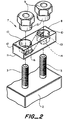
- FIG 2 An adapter 7 of the invention is shown in figure 2, in position ready to be placed over binding posts 3 of a prior art terminal block housing 2.
- the adapter 7 comprises a housing 8 and caps 9.
- the housing 8 has two first apertures 10 extending from a first surface 11, which will lie adjacent the terminal block, to a second surface 12.
- the first apertures have greater size 13 at the second surface 12, and smaller size 14 at the first surface 11.
- the greater size 13 is for accommodation of a part 15 of the caps 9, and the smaller size 14 is for accommodation of the binding posts 3.
- a second aperture 16 passes between, and is in communication with each of, the first apertures.
- a multi-core drop wire may be positioned in the second aperture, such that respective cores of the drop wire pass through respective first apertures.
- the second aperture preferably breaks into the first aperture to such an extent that less than 67% (more preferably less than 50%) of a transverse domension of the second aperture lies within the first aperture. In this way only one core of a two core drop wire will lie within any given first aperture and be capable of being contacted by any given cap.
- the adapter may have more than two first apertures, and may have more than one second aperture.
- the adapter may be used in conjunction with means for providing electrical protection to the circuits to be connected, for example against lightning strikes.
- Such protection may comprise a block that is first positioned over the binding posts, and which has its own binding posts over which the adapter is in turn positioned.
- the protection may operate by switching high voltages to ground.
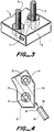
- a terminal block 2 is shown in figure 3. It is not, however, the subject of the present claims.
- This block 2 may be regarded as similar to a series of adapters having binding posts 3 fixed thereto.
- a first terminal block aperture 17 can be seen to pass between the binding posts 3, and is capable of receiving a multi-core drop wire such that respective cores thereof are adjacent respective binding posts.
- Reference to the first aperture passing between the binding posts is to be taken to include a situation where the binding posts stop short of the level in the block of the aperture, or in other words where the aperture is above (as drawn) the tops of the binding posts.
- the caps may have threaded portion that extend down below a part that engage the drop wire in order to meet the binding posts.
- the binding posts have the form of bolts, and the caps have the form of nuts.
- the aperture will preferably be positioned above the tops of the binding posts.
- the terminal block preferably has from 2-25 pairs of binding posts, only one pair being shown.
- the conductors of a multi-core cable to be connected to drop wires may be connected to the binding posts in any suitable way, for example by soldering to their bases.
- Figure 4 is a plan view of a preferred adapter housing 12 of the invention.
- the two parts 13, 14 of the first apertures can be seen, as can the path of the second aperture 16.
- a multi-core drop wire 18, having two conductor cores 19, is shown ready to be slid into the aperture 16.
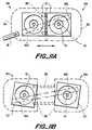
- the adapter housing 12 is shaped in figure 4 to provide a better fit when several such housings are placed side-by-side on a terminal block. This is shown in figure 5.
- first side 20 of each terminal block has a substantially similar shape to the combined shape of a second side 21 plus a substantially straight drop wire 18 extending therefrom.
- figure 5B The design of figure 5B is similar to that of figure 5A, but the binding posts of each pair are staggered along the length of the block. This allows the drop wires to leave the adaptors on the block in a direction substantially perpendicular to the long sides of the block. A close-packing arrangement of the adaptors may still be achieved.
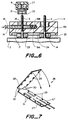
- Figure 6 is a partial section through a part of an adapter having a drop wire 18 inserted therein, and positioned over a terminal block housing 2 and binding posts 3.
- the drop wire 18 can be seen within aperture 17 and passing behind the left-hand binding post 3 such that core 19A will be contacted by cap 9 when screwed down over that binding post.
- the drop wire 17 then passes out of the section in front of, and adjacent the right-hand binding post. Core 19B will be contacted by a cap on that binding post.
- the cap 9 can be seen to have an internal screw thread, which engages screw threads of the binding post 3.
- the cap also has a part 15 that will extend into an upper part 13 of the first aperture, a base of the part 15 having an insulation displacement cutting edge 22 that cuts through insulation of the drop wire to contact a core thereof.
- the cutting edge 22 is prevented from severing a core by its grounding on the base 13A of the wide upper part 13 of the first aperture.
- the cap may be provided with a sealing material such as a gel, preferably in the form of a collar 23.
- the adapter housing may have a recess 24 within which may be positioned a sealing material such as a gel, again preferably in the form of a collar 25.
- a sealing material such as a gel
- the adapter housing is forced against the terminal block housing 2, thus causing the sealing material to be displaced around the surfaces of the binding posts, cap and drop wire.
- the sealing material may be retained under compression by some means for example by the extent to which the cap is tightened on the binding post.
- the cap When the cap is in position it can be seen to make electrical connection from the core of the drop wire to the binding post, which in turn may be connected to a conductor of a multi-core telecommunications cable.
- the contact between the cap and the core may be maintained by some resilient bias, for example that provided by compression of the insulation of the drop wire under the core, or by other means.
- the adapter and terminal block of the invention may be used with stripped multi-core drop wires or with pairs of single core drop wires. If desired, some means may be provided to hold two such single core drop wires in proper position relative to one another, for example by providing some holding means that may be folded around the pair or into which the pair may be slid. In this way, a multi-core drop wire may be said to be formed from single core wires.
- the insulation-displacing caps may then cut through this holding means in the same way that it cuts through the insulation of a two-core drop wire. We prefer that this holding means can be folded around the pair and that two parts of it can snap together, optionally causing the drop wires to be cut to length.
- a holding means 26 is illustrated, together with a pair of drop wires 27 in figure 7. It may have a live hinge 28, means 29 for locking it closed, cutting means 30 for cutting the wires 27 to length, and means 31 for locating the wires.
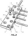
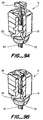
- Figure 8 shows a novel terminal block 2 having female screw-threaded binding posts 31. It is not, however, the subject of the present claims.
- the caps 9 have male screw-threads 32, which can be screwed into the binding posts 31.
- the caps may also have an insulation-displacement cutting edge 22.
- Drop wires 18 are shown entering apertures 17.
- the conductors of a multi-core cable 33 may be connected to the posts 31 at the base of the block 2.
- the binding posts 31 may lie flush with bases of apertures 10 in which case the threads 32 will extend below edges 22 of the caps. Alternatively, the posts 31 may extend above the bases of the apertures 10 (as drawn), in which case the threads 32 need not extend below edges 22.
- Drop wire guide or support means 34 are also shown.
- Figures 9A and 9B show, in partial section, a preferred cap 9 having male screw-threads 32.
- the cap has an insulation cutting edge 22 and a sealing material 23.
- the block (or adapter) with which such caps are used need be provided with no sealing material, since where desired it can be supplied in the caps. Thus, if sealing material becomes ineffective or partially lost, a new cap, pre-filled with sealing material, can be used.
- the cap may be provided with means 35, for example as a screw-threaded or other plug, that can make and break electrical connection between the external screw threads 32 and the insulation cutter 22.
- the means 35 is partially removed thus breaking connection between threads 32 and cutter 22, thus breaking connection between the multi-core cable and the drop wire.
- the means 35 is screwed home, thus making the connection.
- This make and break capability may be useful for selective testing of different parts of a telephone circuit employing a terminal block of the invention.
- breaking of the contact may require slight unscrewing of the cap 9, the means 35 being provided merely to cover a hole in the cap, which hole may serve to provide a contact point for a testing probe.
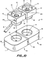
- Figures 10-13 illustrate adapters having a variable separation between first aperture thereof.
- Such an adapter preferably has two first apertures but may have more.
- Figure 10 illustrates in disassembled form an adapter comprising a housing 8 having two parts, a first part 8A at the left-hand side of the figure and a second part 8B at the right hand side of the Figure.
- One first aperture 10 runs through the first part 8A and a second first aperture 10 runs through the second part 8B.
- Each of the first and second parts 8A, 8B comprises a base 36 and a wire-holder 37.
- a portion 16A of the second aperture lies in the wire holder 37 of the first part 8A and another portion 16B lies within the wire-holder 37 of the second part 8B.
- the second aperture will extend right through one of the wire holders, and be blind in the other wire holder.
- the second aperture is preferably of non-circular, generally substantially rectangular or oval, cross-section for close-fitting receipt of a multi-core drop-wire 18.
- the base of the first part may be unconnected to that of the second part, but we prefer that they be connected together, for example slidably connected together.
- One technique of slidable connection comprises telescoping of the first and second parts together, for example by telescoping of pins 38 mounted on one base into apertures in the other base. Sliding, or other movement of one base (or part in general) relative to the other results in a change in the separation between the two first apertures 10.
- a given adapter may be used on design of terminal block having different separations between its binding posts.
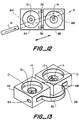
- each is each of a pair is able to be angularly rotated about an axis of a respective first aperture therein without orbital rotation of one part about the other.
- the rotation allows the portion 16A and the other portion 16B of the second aperture to be and to remain mutually parallel since this will facititate insertion of the drop wire 18.
- the wire holders 36 may have a circular protrusion 39 at their undersides which allows rotational mounting in a surface of the base.
- Figure 12 shows a variation on the design of figures 10 and 11, in which the first and second parts 8A, 8B are slidably fixed to each other, the direction of sliding being substantially parallel to a substantially straight line along which lie the portion 16A and other portion 16B of the second aperture.
- the pins 38 or other means can be seen to be set at the desired orientation, generally parallel to the portions 16A and 16B.
- the adapter of figure 13 comprises a first part 8A and a second part 8B, each of which may be of unitary construction or made of two or more pieces that are fixed, preferably, immovably, together.
- Each part has a first aperture 10 having an upper part 13 (as drawn) of larger diameter for receipt of a cap, and a lower part 14 of smaller diameter through which a binding post protrude.
- the first and second parts 8A, 8B may be interconnected by a flexible connector 40.
- the connector may comprise a wire, or cord or yarn, or a web of a material.
- Such a connector 40 may be bonded to a surface of the parts 8A, 8B, may be inserted into a slot in the parts or may be integral with each part. If desired, the connector may be adjustable in the sense that the separation between the parts 8A and 8B can be altered and then at least temporarily fixed at tne new value.
- the first surfaces of the parts 8A, 8B may have a recess preferably substantially concentric with the first apertures, which recess may contain a sealing material such as a gel. Such a sealing material may provide an environmental seal around binding posts that enter the first apertures.
- a part (8A or 8B) of the two part adapter of the general type shown in figure 13, but without the web 40 may be supplied and used alone, ie. without the other of its pair, or they may be used in pairs but supplied without the web.
- the invention provides a terminal block with, an adapter for making electrical connections, particularly in the telecommunications network, and particularly to multi-core cables.
- an adapter for making electrical connections, particularly in the telecommunications network, and particularly to multi-core cables.
- Any of the housing, cap, binding posts, cutters, sealing means, etc. may be chosen.
Landscapes
- Connections Arranged To Contact A Plurality Of Conductors (AREA)
- Cable Accessories (AREA)
- Input Circuits Of Receivers And Coupling Of Receivers And Audio Equipment (AREA)
- Telephone Function (AREA)
- Connector Housings Or Holding Contact Members (AREA)
- Connections By Means Of Piercing Elements, Nuts, Or Screws (AREA)
- Exchange Systems With Centralized Control (AREA)
Claims (26)
- Klemmenblock (1), der wenigstens ein Paar von Klemmenbolzen (3) hat, die von einer Oberfläche des Klemmenblocks vorstehen, gekennzeichnet durch einen Adapter (7), mit dessen Hilfe Seelen einer Mehrseelen-Hausanschlußleitung (18) mit einem Paar von Klemmenbolzen (3) des Klemmenblocks (2) verbunden werden können, wobei der Adapter folgendes aufweist:(a) zwei Kappen (9), die auf jeweiligen Klemmenbolzen (3) aufgenommen werden können, und(b) ein Gehäuse (8), das folgendes hat:(i) zwei erste Öffnungen (10), die jeweils von einer ersten Oberfläche (11) zu einer zweiten Oberfläche (12) des Gehäuses (8) verlaufen, wobei das Gehäuse mit der ersten Oberfläche benachbart dem Klemmenblock (2) und den Klemmenbolzen (3) innerhalb der jeweiligen ersten Öffnungen positionierbar ist, so daß die Klemmenbolzen entsprechende Kappen an der zweiten Oberfläche aufnehmen können, wobei sich die Kappen in die jeweiligen ersten Öffnungen erstrecken;(ii) eine zweite Öffnung (16), die zwischen den ersten Öffnungen (10) verläuft und mit jeder der ersten Öffnungen (10) in Kommunikation ist, wobei jede erste Öffnung die zweite Öffnung an verschiedenen Querseiten davon schneidet und wobei die zweite Öffnung (16) fähig ist, die Hausanschlußleitung aufzunehmen, so daß jeweilige Seelen derselben durch entsprechende erste Öffnungen (10) verlaufen und mit entsprechenden Kappen (9) in Kontakt gelangen, wenn sie von entsprechenden Klemmenbolzen (3) innerhalb der ersten Öffnungen (10) aufgenommen sind.
- Klemmenblock nach Anspruch 1, wobei die Kappen (9) Gewinde haben, so daß sie auf Gewinde aufweisende Klemmenbolzen (3) schraubbar sind.
- Klemmenblock nach Anspruch 1, wobei jede Kappe eine Isolierungsverdrängungseinrichtung (22) hat, die Isolierung einer Hausanschlußleitung verdrängen kann.
- Klemmenblock nach Anspruch 1, wobei das Gehäuse eine Einrichtung (13A) hat, die das Ausmaß begrenzt, bis zu dem die Kappen jeweils in den ersten Öffnungen aufgenommen werden können.
- Klemmenblock nach Anspruch 4, wobei die begrenzende Einrichtung eine Schulter (13A) in jeder der ersten Öffnungen (10) aufweist und die Öffnungen an der zweiten Oberfläche jeweils größer als an der ersten Oberfläche sind.
- Klemmenblock nach Anspruch 1, wobei jede der ersten Öffnungen (10) im wesentlichen Kreisquerschnitt hat.
- Klemmenblock nach Anspruch 1, wobei die zweite Öffnung (16) nichtkreisförmigen Querschnitt hat, so daß die Seelen (19) einer darin befindlichen Hausanschlußleitung mit nichtkreisförmigem Querschnitt in unveränderlicher Orientierung in bezug auf die ersten Öffnungen gehalten werden.
- Klemmenblock nach Anspruch 1, der zusätzlich aufweist:
(a) ein Dichtmaterial (23, 25) an jeder der ersten Öffnungen und/oder im Inneren jeder der Kappen. - Klemmenblock nach Anspruch 8, wobei das Dichtmaterial einen Konuspenetrationswert, gemessen nach ASTM D217-68 bei 21 °C, von 100 bis 350 (10⁻¹ mm) und eine Bruchdehnung, gemessen nach ASTM D638-80 bei 21 °C, von wenigstens 200 % hat.
- Klemmenblock nach Anspruch 1, wobei die zweite Öffnung (16) im wesentlichen gerade ist.
- Klemmenblock nach Anspruch 10, wobei das Gehäuse eine erste und eine zweite Seite (20, 21) hat, die zwischen der ersten und der zweiten Oberfläche verlaufen;wobei die zweite Öffnung in einer Öffnung in der zweiten Seite endet; unddie erste Seite (20) eine Gestalt hat, die der kombinierten Gestalt der zweiten Seite (21) plus einer davon verlaufenden, im wesentlichen geraden Hausanschlußleitung (18) gleicht, so daß zwei oder mehr der Adapter nebeneinander in einer im wesentlichen dicht gepackten Konfiguration positioniert werden können.
- Klemmenblock nach Anspruch 1, wobei die zweite Öffnung (16) langgestreckt und im Querschnitt geschlossen ist.
- Klemmenblock nach Anspruch 1, wobei das Gehäuse einen ersten und einen zweiten Teil (8A, 8B) aufweist;wobei der erste Teil (8A) darin eine der ersten Öffnungen (10) und einen Bereich der zweiten Öffnung (16) hat;der zweite Teil (8B) darin eine andere der ersten Öffnungen (10) und einen anderen Bereich der zweiten Öffnung (16) hat;der erste Teil relativ zu dem zweiten Teil bewegbar ist.
- Klemmenblock nach Anspruch 13, wobei der erste und der zweite Teil (8A, 8B) so angeordnet sein können, daß Achsen der zwei ersten Öffnungen im wesentlichen parallel sind, und der erste Teil relativ zu dem zweiten Teil so bewegbar ist, daß nach dem Bewegen die genannten Achsen im wesentlichen parallel bleiben und die Entfernung zwischen ihnen geändert worden ist.
- Klemmenblock nach Anspruch 13, wobei der erste und der zweite Teil (8A, 8B) so angeordnet sein können, daß Achsen des genannten Bereichs der zweiten Öffnung und des anderen Bereichs der zweiten Öffnung entlang einer gemeinsamen, im wesentlichen geraden Linie liegen.
- Klemmenblock nach Anspruch 15, wobei der erste und der zweite Teil (8A, 8B) gleitbar aneinander befestigt sind und die Gleitrichtung parallel zu der im wesentlichen geraden Linie ist.
- Klemmenblock nach Anspruch 14, wobei der erste und der zweite Teil (8A, 8B) jeweils um eine Achse einer jeweiligen ersten Öffnung darin winkelmäßig drehbar sind ohne eine Orbitaldrehung eines Teils um den anderen.
- Klemmenblock nach Anspruch 13, wobei die Orientierung des ersten Teils relativ zu derjenigen des zweiten Teils unveränderlich ist, so daß Achsen der beiden ersten Öffnungen im wesentlichen parallel zueinander sind und bei der Bewegung des ersten Teils relativ zu dem zweiten Teil im wesentlichen parallel zueinander bleiben.
- Klemmenblock nach Anspruch 13, wobei jeder von dem ersten und dem zweiten Teil folgendes aufweist:eine Basis (36); undeinen Leiterhalter (37);wobei der Leiterhalter in der Basis drehbar angebracht ist;wobei ein Teil der zweiten Öffnung (16) durch wenigstens einen Teil des Leiterhalters verläuft; die erste Öffnung (10) durch den Leiterhalter (37) und die Basis (36) verläuft; unddie Basis (36) des ersten Teils (8A) an der Basis (36) des zweiten Teils (8B) gleitbar festgelegt ist, so daß der Abstand zwischen Achsen der beiden ersten Öffnungen geändert werden kann.
- Klemmenblock nach Anspruch 19, wobei jede Basis darin eine Ausnehmung an einer Oberfläche hat, die zu derjenigen entgegengesetzt ist, in der der Leiterhalter drehbar angebracht ist, wobei die Ausnehmung mit der ersten Öffnung im wesentlichen konzentrisch ist.
- Klemmenblock nach Anspruch 20, wobei die Ausnehmung ein Dichtmaterial enthält.
- Klemmenblock nach Anspruch 13, wobei jeder von dem ersten und dem zweiten Teil (8A, 8B) darin eine Ausnehmung an der ersten Oberfläche hat, wobei die Ausnehmung mit der ersten Öffnung im wesentlichen konzentrisch ist.
- Klemmenblock nach Anspruch 22, wobei die Ausnehmung ein Dichtmaterial enthält.
- Klemmenblock nach Anspruch 13, wobei der erste und der zweite Teil nicht miteinander verbunden sind.
- Klemmenblock nach Anspruch 13, wobei der genannte Bereich und der genannte andere Bereich der zweiten Öffnung nichtkreisförmigen Querschnitt haben und wobei die zweite Öffnung in jede der ersten Öffnungen in einem solchen Ausmaß eindringt, daß weniger als 67 % einer Querdimension der zweiten Öffnung innerhalb jeder ersten Öffnung liegt.
- Klemmenblock nach Anspruch 13, wobei der erste und der zweite Teil durch einen flexiblen Steg (40) miteinander verbunden sind.
Applications Claiming Priority (7)
| Application Number | Priority Date | Filing Date | Title |
|---|---|---|---|
| US16430188A | 1988-03-04 | 1988-03-04 | |
| US16426188A | 1988-03-04 | 1988-03-04 | |
| US164261 | 1988-03-04 | ||
| US23175588A | 1988-08-12 | 1988-08-12 | |
| US231755 | 1988-08-12 | ||
| PCT/US1989/000893 WO1989008338A1 (en) | 1988-03-04 | 1989-03-04 | Telecommunications terminal block |
| US164301 | 1993-12-08 |
Publications (2)
| Publication Number | Publication Date |
|---|---|
| EP0403531A1 EP0403531A1 (de) | 1990-12-27 |
| EP0403531B1 true EP0403531B1 (de) | 1996-01-24 |
Family
ID=27388989
Family Applications (1)
| Application Number | Title | Priority Date | Filing Date |
|---|---|---|---|
| EP89903328A Expired - Lifetime EP0403531B1 (de) | 1988-03-04 | 1989-03-04 | Fernmeldeanschluss-klemmenblock |
Country Status (10)
| Country | Link |
|---|---|
| EP (1) | EP0403531B1 (de) |
| JP (1) | JPH03503330A (de) |
| KR (1) | KR900701059A (de) |
| AT (1) | ATE133515T1 (de) |
| AU (1) | AU634156B2 (de) |
| BR (1) | BR8907302A (de) |
| CA (1) | CA1298895C (de) |
| DE (1) | DE68925528T2 (de) |
| MX (1) | MX170026B (de) |
| WO (1) | WO1989008338A1 (de) |
Cited By (1)
| Publication number | Priority date | Publication date | Assignee | Title |
|---|---|---|---|---|
| CN103779072A (zh) * | 2014-01-27 | 2014-05-07 | 浙江南德电气有限公司 | 螺丝辅助固定结构及相应的低压智能电力电容器 |
Families Citing this family (2)
| Publication number | Priority date | Publication date | Assignee | Title |
|---|---|---|---|---|
| US5069636A (en) * | 1987-07-07 | 1991-12-03 | Raychem Corporation | Terminal block and adapter |
| US6646207B1 (en) * | 2000-05-12 | 2003-11-11 | Thomson Licensing S. A. | Double helix lead dressing of flat flexible cables |
Family Cites Families (10)
| Publication number | Priority date | Publication date | Assignee | Title |
|---|---|---|---|---|
| DE501100C (de) * | 1930-06-27 | Arthur Schuetz Dipl Ing | Schalttafelklemme mit vorderseitigem Leitungsanschluss | |
| FR558301A (fr) * | 1922-11-06 | 1923-08-25 | Raccord de dérivation pour canalisations électriques ou autres | |
| FR587574A (fr) * | 1924-10-17 | 1925-04-21 | Boîte de jonction à dérivation | |
| US2654857A (en) * | 1949-10-27 | 1953-10-06 | Finkel Julius | Antenna accessory |
| US3016510A (en) * | 1958-07-23 | 1962-01-09 | Blonder Tongue Elect | Electrical clamp-and-connector |
| US3688246A (en) * | 1968-06-06 | 1972-08-29 | John A Toedtman | Electrical connector with insulation-piercing contact pins |
| US3771104A (en) * | 1971-08-10 | 1973-11-06 | M Clark | Modular element for a solderless expandable terminal strip |
| DE2256657A1 (de) * | 1972-11-18 | 1974-05-22 | Bbc Brown Boveri & Cie | Anschluss- oder lichtauslassdose insbesondere zum verbinden von deckenleuchten |
| DE3627041A1 (de) * | 1986-08-09 | 1988-02-18 | Multi Contact Ag | Elektrische kontaktanordnung fuer eine insbesondere als mehradriges kabel ausgebildete leiteranordnung |
| US4734061A (en) * | 1986-12-31 | 1988-03-29 | Bell Communications Research, Inc. | Telecommunications terminal block |
-
1989
- 1989-03-03 CA CA000592693A patent/CA1298895C/en not_active Expired - Fee Related
- 1989-03-03 MX MX015148A patent/MX170026B/es unknown
- 1989-03-04 JP JP1503161A patent/JPH03503330A/ja active Pending
- 1989-03-04 KR KR1019890702053A patent/KR900701059A/ko not_active Abandoned
- 1989-03-04 BR BR898907302A patent/BR8907302A/pt not_active IP Right Cessation
- 1989-03-04 AU AU33524/89A patent/AU634156B2/en not_active Ceased
- 1989-03-04 EP EP89903328A patent/EP0403531B1/de not_active Expired - Lifetime
- 1989-03-04 WO PCT/US1989/000893 patent/WO1989008338A1/en not_active Ceased
- 1989-03-04 AT AT89903328T patent/ATE133515T1/de not_active IP Right Cessation
- 1989-03-04 DE DE68925528T patent/DE68925528T2/de not_active Expired - Fee Related
Cited By (2)
| Publication number | Priority date | Publication date | Assignee | Title |
|---|---|---|---|---|
| CN103779072A (zh) * | 2014-01-27 | 2014-05-07 | 浙江南德电气有限公司 | 螺丝辅助固定结构及相应的低压智能电力电容器 |
| CN103779072B (zh) * | 2014-01-27 | 2016-08-24 | 浙江南德电气有限公司 | 螺丝辅助固定结构及相应的低压智能电力电容器 |
Also Published As
| Publication number | Publication date |
|---|---|
| AU634156B2 (en) | 1993-02-18 |
| DE68925528T2 (de) | 1996-09-19 |
| WO1989008338A1 (en) | 1989-09-08 |
| CA1298895C (en) | 1992-04-14 |
| KR900701059A (ko) | 1990-08-17 |
| BR8907302A (pt) | 1991-03-19 |
| DE68925528D1 (de) | 1996-03-07 |
| AU3352489A (en) | 1989-09-22 |
| ATE133515T1 (de) | 1996-02-15 |
| EP0403531A1 (de) | 1990-12-27 |
| JPH03503330A (ja) | 1991-07-25 |
| MX170026B (es) | 1993-08-04 |
Similar Documents
| Publication | Publication Date | Title |
|---|---|---|
| US5173060A (en) | Telecommunications terminal block or adapter | |
| EP0402374B1 (de) | Anschlussleiste für fernmeldverbindungen | |
| US5647760A (en) | Insulation displacement contact including retention means | |
| US5273449A (en) | Modular telecommunications terminal block | |
| AU633932B2 (en) | Insulation displacing barrel terminal | |
| CA2114417C (en) | Improved cross connect system for telecommunications systems | |
| CA1241080A (en) | Insulation displacement connector terminal block | |
| US6729900B2 (en) | Transmission line connectors with interchangeable module units | |
| US5153988A (en) | Method of making modular telecommunications terminal block | |
| US5219302A (en) | Crossconnect terminal block | |
| US5069636A (en) | Terminal block and adapter | |
| US5622516A (en) | Insulation displacement terminal with two-wire insertion capability | |
| EP0298713B1 (de) | Klemmenleiste und Adapter | |
| EP0403531B1 (de) | Fernmeldeanschluss-klemmenblock | |
| US5470250A (en) | Bridging terminal block | |
| US4212507A (en) | Selective interconnection system and connector | |
| US5013877A (en) | Devices for electrical connection | |
| CA1227256A (en) | Cable terminal connector with insulation displacing terminals | |
| EP0408582B1 (de) | Fernsprecher-verbindungsdose sowie schalter dafür | |
| US20080223613A1 (en) | Repositionable insulator | |
| CA2621878C (en) | Field data distribution system with fiber optic converter | |
| EP0605426A4 (en) | Telecommunications terminal block and terminal therefor. |
Legal Events
| Date | Code | Title | Description |
|---|---|---|---|
| PUAI | Public reference made under article 153(3) epc to a published international application that has entered the european phase |
Free format text: ORIGINAL CODE: 0009012 |
|
| 17P | Request for examination filed |
Effective date: 19900817 |
|
| AK | Designated contracting states |
Kind code of ref document: A1 Designated state(s): AT BE CH DE FR GB IT LI NL SE |
|
| 17Q | First examination report despatched |
Effective date: 19930526 |
|
| GRAA | (expected) grant |
Free format text: ORIGINAL CODE: 0009210 |
|
| AK | Designated contracting states |
Kind code of ref document: B1 Designated state(s): AT BE CH DE FR GB IT LI NL SE |
|
| PG25 | Lapsed in a contracting state [announced via postgrant information from national office to epo] |
Ref country code: IT Free format text: LAPSE BECAUSE OF FAILURE TO SUBMIT A TRANSLATION OF THE DESCRIPTION OR TO PAY THE FEE WITHIN THE PRESCRIBED TIME-LIMIT;WARNING: LAPSES OF ITALIAN PATENTS WITH EFFECTIVE DATE BEFORE 2007 MAY HAVE OCCURRED AT ANY TIME BEFORE 2007. THE CORRECT EFFECTIVE DATE MAY BE DIFFERENT FROM THE ONE RECORDED. Effective date: 19960124 Ref country code: LI Free format text: LAPSE BECAUSE OF FAILURE TO SUBMIT A TRANSLATION OF THE DESCRIPTION OR TO PAY THE FEE WITHIN THE PRESCRIBED TIME-LIMIT Effective date: 19960124 Ref country code: CH Free format text: LAPSE BECAUSE OF FAILURE TO SUBMIT A TRANSLATION OF THE DESCRIPTION OR TO PAY THE FEE WITHIN THE PRESCRIBED TIME-LIMIT Effective date: 19960124 Ref country code: AT Effective date: 19960124 Ref country code: BE Effective date: 19960124 Ref country code: NL Free format text: LAPSE BECAUSE OF FAILURE TO SUBMIT A TRANSLATION OF THE DESCRIPTION OR TO PAY THE FEE WITHIN THE PRESCRIBED TIME-LIMIT Effective date: 19960124 |
|
| REF | Corresponds to: |
Ref document number: 133515 Country of ref document: AT Date of ref document: 19960215 Kind code of ref document: T |
|
| PGFP | Annual fee paid to national office [announced via postgrant information from national office to epo] |
Ref country code: FR Payment date: 19960126 Year of fee payment: 8 |
|
| REF | Corresponds to: |
Ref document number: 68925528 Country of ref document: DE Date of ref document: 19960307 |
|
| ET | Fr: translation filed | ||
| PG25 | Lapsed in a contracting state [announced via postgrant information from national office to epo] |
Ref country code: GB Effective date: 19960424 Ref country code: SE Effective date: 19960424 |
|
| NLV1 | Nl: lapsed or annulled due to failure to fulfill the requirements of art. 29p and 29m of the patents act | ||
| REG | Reference to a national code |
Ref country code: CH Ref legal event code: PL |
|
| PLBE | No opposition filed within time limit |
Free format text: ORIGINAL CODE: 0009261 |
|
| STAA | Information on the status of an ep patent application or granted ep patent |
Free format text: STATUS: NO OPPOSITION FILED WITHIN TIME LIMIT |
|
| PG25 | Lapsed in a contracting state [announced via postgrant information from national office to epo] |
Ref country code: DE Effective date: 19961203 |
|
| GBPC | Gb: european patent ceased through non-payment of renewal fee |
Effective date: 19960424 |
|
| 26N | No opposition filed | ||
| PG25 | Lapsed in a contracting state [announced via postgrant information from national office to epo] |
Ref country code: FR Free format text: LAPSE BECAUSE OF NON-PAYMENT OF DUE FEES Effective date: 19971128 |
|
| REG | Reference to a national code |
Ref country code: FR Ref legal event code: ST |