EP0403464B1 - Amboss - Google Patents
Amboss Download PDFInfo
- Publication number
- EP0403464B1 EP0403464B1 EP90870091A EP90870091A EP0403464B1 EP 0403464 B1 EP0403464 B1 EP 0403464B1 EP 90870091 A EP90870091 A EP 90870091A EP 90870091 A EP90870091 A EP 90870091A EP 0403464 B1 EP0403464 B1 EP 0403464B1
- Authority
- EP
- European Patent Office
- Prior art keywords
- anvil
- base
- post
- forging
- longitudinal axis
- Prior art date
- Legal status (The legal status is an assumption and is not a legal conclusion. Google has not performed a legal analysis and makes no representation as to the accuracy of the status listed.)
- Revoked
Links
- 238000005242 forging Methods 0.000 claims description 17
- 229910000831 Steel Inorganic materials 0.000 claims description 16
- 239000010959 steel Substances 0.000 claims description 16
- 239000000835 fiber Substances 0.000 claims description 9
- 238000004519 manufacturing process Methods 0.000 claims description 6
- 238000000034 method Methods 0.000 claims description 5
- PXHVJJICTQNCMI-UHFFFAOYSA-N Nickel Chemical compound [Ni] PXHVJJICTQNCMI-UHFFFAOYSA-N 0.000 claims description 4
- 238000000137 annealing Methods 0.000 claims description 4
- 238000003754 machining Methods 0.000 claims description 4
- 238000007493 shaping process Methods 0.000 claims description 4
- 229910052782 aluminium Inorganic materials 0.000 claims description 3
- XAGFODPZIPBFFR-UHFFFAOYSA-N aluminium Chemical compound [Al] XAGFODPZIPBFFR-UHFFFAOYSA-N 0.000 claims description 3
- 238000003780 insertion Methods 0.000 claims description 3
- 230000037431 insertion Effects 0.000 claims description 3
- 238000003466 welding Methods 0.000 claims description 3
- 229910000851 Alloy steel Inorganic materials 0.000 claims description 2
- 229910000975 Carbon steel Inorganic materials 0.000 claims description 2
- VYZAMTAEIAYCRO-UHFFFAOYSA-N Chromium Chemical compound [Cr] VYZAMTAEIAYCRO-UHFFFAOYSA-N 0.000 claims description 2
- ZOKXTWBITQBERF-UHFFFAOYSA-N Molybdenum Chemical compound [Mo] ZOKXTWBITQBERF-UHFFFAOYSA-N 0.000 claims description 2
- 239000010962 carbon steel Substances 0.000 claims description 2
- 238000010438 heat treatment Methods 0.000 claims description 2
- 229910052750 molybdenum Inorganic materials 0.000 claims description 2
- 239000011733 molybdenum Substances 0.000 claims description 2
- 229910052759 nickel Inorganic materials 0.000 claims description 2
- 238000010791 quenching Methods 0.000 claims description 2
- 230000000171 quenching effect Effects 0.000 claims description 2
- 238000005496 tempering Methods 0.000 claims description 2
- XEEYBQQBJWHFJM-UHFFFAOYSA-N Iron Chemical compound [Fe] XEEYBQQBJWHFJM-UHFFFAOYSA-N 0.000 description 17
- 235000000396 iron Nutrition 0.000 description 15
- 229910052742 iron Inorganic materials 0.000 description 9
- 241000283073 Equus caballus Species 0.000 description 8
- 208000031968 Cadaver Diseases 0.000 description 7
- 229910052751 metal Inorganic materials 0.000 description 7
- 239000002184 metal Substances 0.000 description 7
- 241000777300 Congiopodidae Species 0.000 description 2
- 241000283086 Equidae Species 0.000 description 2
- 239000011324 bead Substances 0.000 description 2
- 241001080024 Telles Species 0.000 description 1
- 210000003484 anatomy Anatomy 0.000 description 1
- 230000015572 biosynthetic process Effects 0.000 description 1
- 229910052804 chromium Inorganic materials 0.000 description 1
- 239000011651 chromium Substances 0.000 description 1
- 230000006835 compression Effects 0.000 description 1
- 238000007906 compression Methods 0.000 description 1
- 238000005520 cutting process Methods 0.000 description 1
- 238000000605 extraction Methods 0.000 description 1
- 150000002505 iron Chemical class 0.000 description 1
- 239000000463 material Substances 0.000 description 1
- 238000005555 metalworking Methods 0.000 description 1
- 239000002994 raw material Substances 0.000 description 1
- 230000007704 transition Effects 0.000 description 1
Images

Classifications
-
- B—PERFORMING OPERATIONS; TRANSPORTING
- B21—MECHANICAL METAL-WORKING WITHOUT ESSENTIALLY REMOVING MATERIAL; PUNCHING METAL
- B21J—FORGING; HAMMERING; PRESSING METAL; RIVETING; FORGE FURNACES
- B21J19/00—Blacksmiths requisites not otherwise provided for
- B21J19/04—Anvils; Associated items
Definitions
- the invention relates to portable anvils intended in particular for farriery and more specifically a so-called “bigorne” model comprising, on either side of a table, two horns, one round, the other square, this portable bigorne allowing a farrier to practice his art with maximum ease, even in itinerant conditions.
- the farrier no longer has to make the iron, but more simply he must choose the appropriate iron and adjust this iron at the foot of the horse.
- a traditional anvil, made of cast metal, is by no means portable and weighs up to 200 to 300 kg.
- Makeshift means metal blocks of any shape are not very recommendable for the quality of work expected of a good craftsman.
- Anvils of goldsmiths do not support the energy deployed, nor do they allow to obtain the desired curves.
- Document DE-C-448 080 describes an anvil formed from an ingot, one end of which is formed as a base, the other end being crushed, perpendicular to the initial axis of the ingot, the fibers metal roughly aligned along the axis of the table.
- the resistance of the metal although increased, does not make it possible to obtain a light anvil with a large working surface.
- Application GB-A-273 634 describes a method of manufacturing an anvil by oxy-cutting from a metal ingot, various parts being able to be subsequently added by welding.
- Application GB-A-273,634 does not, however, give any indication of a way of making a particularly resistant anvil, of reduced weight and with a large working surface.
- the object of the invention is to produce an anvil, essentially for the use of farriery, easily transportable by a single man, with extended worktops and nevertheless having excellent robustness.
- Another object is that this anvil offers a wide variety of support points for shaping metal objects.
- a more particular purpose of this anvil is to be able to work horseshoes of all sizes there.
- Another object is that this anvil has a long life.
- Another aim is the placing on the market of a tool for working with high quality iron, with a reasonable manufacturing cost.
- the object of the invention is a portable steel anvil extending along a substantially horizontal longitudinal axis and along a vertical axis and comprising a base, a body comprising a round horn and a square horn arranged on either side of it. 'a table, along the longitudinal axis, and a shaft connecting the body to the base along the vertical axis; in this anvil, the base is in the form of a plate and has a substantially planar lower face, the length of which along the longitudinal axis is greater than its width in a direction perpendicular to this axis; the barrel flares up and down from an intermediate zone of smaller section; the entire anvil is formed by a first part comprising the body and a barrel section delimited by a plane substantially parallel to the underside of the base and located in said zone of smaller section, and of a second part comprising the base and a barrel section delimited by this same plane; these two parts, connected together by a weld with high resistance to compression and fatigue, have been shaped, by forging
- this anvil weighs between 20 and 30 kg.
- the body of the anvil is made of steel alloyed with nickel, chromium and molybdenum having a high resilience both at high and at low temperature and being able to be forged.
- the base is made of carbon steel capable of being forged.
- the free ends of the two barrel sections preferably have a chamfer on their periphery, these chamfers forming, when the barrel sections are assembled, a groove capable of accommodating a weld bead, the free end of at least one of the two sections being released in its central part, a rib remaining along this periphery.
- the rib advantageously has a width of between 1 and 5 mm.
- the chamfer of the barrel section connected to the body forms, with the plane delimiting the two barrel sections, an angle between 20 and 40 °.
- the chamfer of the barrel section connected to the base forms, with the plane delimiting the two barrel sections, an angle of 10 to 30 °.
- the round horn of the anvil preferably has a width greater than 22 cm.
- the anvil advantageously has a flat surface below the upper surface of the table, parallel to the latter, substantially at the level of the upper edge of the round horn.
- a square opening is made in the upper surface of the table, said opening being of dimensions suitable for the insertion of anvil tools and being pierced right through so that an extractor member for said tools can be inserted through the lower opening of this square opening.
- a work surface is provided between the edge of the square opening and the edge of the table.
- an oval opening, with rounded edges in a plane, suitable for the shaping of aluminum irons crosses the table right through.
- the method further comprises clearing the end of one of the sections of was in its central part, a rib being formed along the periphery of this end.
- the preferential orientation of the fibers gradually changes from an orientation along the longitudinal axis (in the body and in the base) to an orientation along the vertical axis (in the two barrel sections) and this by following deformations that are subjected to the blanks during forging.
- An advantage of the invention is that, because of its manufacturing method, the structure of the steel is oriented axially, which allows, at equal strength, to considerably reduce its shapes and therefore its weight; the central mass of a traditional anvil is here reduced to a pillar with a narrow waist.
- Another advantage is that the horns offer significant clearance, which allows for more precise work.
- each anvil being produced in two pieces, it is possible to use steels of different shades for the base and the body, it is therefore not necessary to use for the base a steel of as good quality as for the body.
- Another advantage is that, given the extent of the work plan, very differentiated work can be carried out with great precision (in particular pulling pliers).
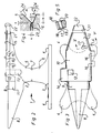
- the anvil according to the invention comprises two separate parts, the body 2 and the base 3. These two parts are arranged along the same horizontal axis.
- the base 3 is flattened and has four feet 4 which extend along the four corners of a quadrilateral whose long side is disposed along the axis of the anvil, the short side of this quadrilateral is wider than the projection of the body 2 on the base 3.
- the body 2 and the base 3 are joined in the middle by two barrel sections 5, 6 which are thinner from each of these two parts 2, 3 and are joined by a weld 7 at their free ends.
- the body 2 is extended along the longitudinal axis by a round horn 8, whose upper edge is horizontal and whose length is, in this example, about 23 cm.
- This horn 8 has a significant clearance over its entire length, it is therefore possible to work the irons therein by presenting them practically from all angles without being obstructed beyond measure by the body 2 or by the base 3.
- a flat surface called "level break” makes the transition between the base of the round horn 8 and a table 10 which occupies the upper face of the body 2.
- This level break 9 has two vertical sides 11 and rounded angles, which makes it possible to conveniently work on irons of larger dimensions, such as irons for draft horses.
- a table 10 with sharp angles extends to the upper part of the body 2, making it possible to carry out conventional work.
- a square opening 12 of standardized dimensions is drilled right through into the table 10. This opening 12 allows tools to be accommodated therein (not shown) suitable for working and shaping iron.
- the lower orifice 13 of the square opening 12 simplifies the extraction of the tools after use (by insertion of a lever, for example).
- a rim 14 with sharp angles is formed and protrudes so that it can pull clips of any size easily.
- the table 10 is extended, at its other end, without a solution of continuity, by the upper face of the square horn 15 (also called heel).
- the upper edges of the square horn are rounded so as to facilitate the opening of irons of different dimensions. It also allows cold irons to be worked.
- constricted section of the barrel (5, 6) of the anvil means that the underside of the square horn 15 is also largely free, which facilitates work.
- stamping makes it possible to further increase the rate of metal working.
- the axis of the dies and the axis of the ingots can be made to coincide, which makes it possible to keep the metal fiber in its original orientation and considerably increase the rate of wrought without additional energy input.
- the table 10 is also pierced right through by an oval groove 17 (shown in section in Fig. 5).
- the angles 18, 19, 20 of this groove 17 are rounded along the plane of its largest sides. Loose irons (such as those used for racehorses) can be slid into this oval groove and worked easily.
- a groove 21 of 10 mm is made transversely near the end 22 of the square horn 15, parallel to this end 22. Any type of iron, even carrying clips, can be uncorked without problem thanks to the presence of this groove 21.
- Fig. 4 shows in more detail the connection of the ends of barrel sections 5, 6.
- the two ends have been pre-machined so as to offer a contact plane substantially parallel to the base 3, the internal face of one of the ends has been released with a thickness e (where e is between 1 and 3 mm) of so as to limit the contact between the two ends to a rib 23 of width a (where a is between 1 and 5 mm) which goes around the barrel, which makes it possible to reduce the tensions linked to differential shrinkage.
- a chamfer 24 is formed on the periphery of each barrel section 5, 6, the wall of this chamfer 24 making, with the plane delimiting the two barrel sections, an angle ⁇ (for the base) and ⁇ (for the body ), ⁇ varying between 10 and 30 ° (with an optimum of 20 °) and ⁇ varying between 40 and 50 ° (with an optimal value of 45 °), the bottom of the throat (c + d) having approximately 2 mm.
- the two chamfers 24 form a groove suitable for drawing a weld bead between the body 2 and the base 3.
Landscapes
- Engineering & Computer Science (AREA)
- Mechanical Engineering (AREA)
- Forging (AREA)
- Orthopedics, Nursing, And Contraception (AREA)
- Rehabilitation Tools (AREA)
- Prostheses (AREA)
Claims (16)
- Aus Stahl bestehender, sich im wesentlichen entlang einer horizontalen und einer vertikalen Achse erstreckender, geweblicher Amboß, mit einer Fußplatte (3), einem ein rundes Horn (8) und ein rechteckiges Horn (15) aufweisenden Grundkörper (2), wobei das runde Horn (8) und das rechteckige Horn (15) beiderseits eines Tisches (10) - in Richtung der Längsachse gesehen - angeordnet sind und mit Schaftstücken (5,6), über welche der Grundkörper (2) mit der Fußplatte (3) in Richtung der Vertikalachse miteinander in Verbindung steht,- wobei die Fußplatte (3) eine plattenartige, durch eine im wesentlichen ebene Unterseite gekennzeichnete Gestalt aufweist, deren Länge in Richtung der Längsachse gesehen größer als ihre Breite in einer Richtung senkrecht zu dieser Längsachse gesehen ist,- dadurch gekennzeichnet,- daß die Schaftstücke (5,6) ausgehend von einer Zwischenzone schwächsten Querschnitt in den Richtungen nach oben bzw. nach unten sich erweiternd ausgebildet sind,- daß die Gesamtheit des Ambosses (1) aus einem ersten, aus dem Grundkörper (2) und einem Schaftstück (5) bestehenden Teil, welches durch eine im wesentlichen parallel zur Unterseite der Fußplatte (3) verlaufende Ebene begrenzt ist, die sich in der genannten Zone schwächsten Querschnitts befindet und einem zweiten Teil gebildet ist, welches aus der Fußplatte (3) und einem Schaftstück (6) besteht, welches durch die gleiche Ebene begrenzt wird,- wobei die beiden genannten Teile über eine gegenüber Werkstoffermüdung und Stauchung höchst widerstandsfähige Schweißnaht (7) untereinander in Verbindung stehen, durch Schmieden hergestellt worden sind, und zwar derart, daß der benutzte Stahl eine Faserstruktur aufweist, deren Fasern vorzugsweise in Richtung der Längsachse des Grundkörpers (2) sowie des Fußteils (3) und in den Schaftstücken in Richtung der Vertikalachse orientiert sind.
- Amboß nach Anspruch 1, dadurch gekennzeichnet, daß das Schmieden eines jeden der Teile des Ambosses durch Gesenkformung bewirkt worden ist.
- Amboß nach einem der vorangegangenen Ansprüche, dadurch gekennzeichnet, daß die Schaftstücke (5,6) im Bereich ihres schwächsten Querschnitts eine Länge aufweisen, die geringer ist als ein Fünftel der, die Endpunkte der Hörner (8,15) trennenden Entfernung, in einer Richtung parallel zur Längsachse des Ambosses gesehen.
- Amboß nach Anspruch 3, dadurch gekennzeichnet, daß die Länge der Schaftstücke (5,6) im Bereich des schwächsten Querschnitts geringer ist als ein Siebentel des Abstands zwischen den Endpunkten der Hörner (8,15).
- Amboß nach einem der vorangegangenen Ansprüche, dadurch gekennzeichnet, daß die Hörner (8,15) derart hergestellt sind, daß auf ihrer Unterseite ausgehend von ihren Endpunkten bis zu ihrer Grundfläche eine bedeutende Ausnehmung besteht, und zwar derart, daß der Benutzer des Ambosses Objekte bearbeiten kann, ohne durch den Grundkörper (2) oder die Fußplatte (3) behindert zu werden.
- Amboß nach einem der Ansprüche 1 bis 5, gekennzeichnet durch ein Gewicht zwischen 20 kg und 30 kg.
- Amboß nach einem der vorangegangenen Ansprüche, dadurch gekennzeichnet, daß der Grundkörper (2) aus einem mit Nickel, Chrom und Molybdän legierten Stahl besteht, der sowohl bei hohen als auch bei niedrigen Temperaturen eine große Schlagzähigkeit aufweist und schmiedefähig ist.
- Amboß nach einem der vorangegangenen Ansprüche, dadurch gekennzeichnet, daß die Fußplatte (3) aus einem schmiedbaren Kohlenstoffstahl besteht.
- Amboß nach einem der vorangegangenen Ansprüche, dadurch gekennzeichnet, daß die freien Enden der beiden Schaftstücke (5,6) im äußeren Urnfangsbereich eine Anphasung (24) aufweisen, wobei diese Anphasungen (24) im zusammengesetzten Zustand der Schaftstücke (5,6) eine zur Aufnahme einer Schweißnaht (7) geeignete Kehlung bilden
- wobei das freie Ende wenigstens eines der beiden Schaftstücke in seinem zentralen Bereich eine Ausnehmung aufweist und wobei sich entlang des äußeren Umfangs eine Rippe (23) erstreckt. - Amboß nach einem der vorangegangenen Ansprüche, dadurch gekennzeichnet, daß das runde Horn (8) eine Länge von mehr als 22 cm aufweist.
- Amboß nach einem der vorangegangenen Ansprüche, gekennzeichnet durch eine viereckige, in der Oberseite des Tisches (10) befindliche Öffnung (12), welche Öffnung zur Aufnahme von Amboßwerkzeugen geeignete Abmessungen aufweist und derart gebohrt ist, daß durch die untere Mündung (13) der viereckigen Öffnung (12) ein Aushebeorgan für die genannten Werkzeuge einführbar ist.
- Amboß nach Anspruch 11, gekennzeichnet durch eine Arbeitsfläche (14), die zwischen den Rändern der viereckigen Öffnung (12) und des Tisches (10) angeordnet ist.
- Amboß nach einem der vorangegangenen Ansprüche, gekennzeichnet durch eine ovale Öffnung (17), deren Kanten in einer, an die Formgebung von aus Aluminium bestehenden Hufeisen angepaßten Ebene abgerundet sind, welche Öffnung (17) den Tisch (10) durchdringt.
- Amboß nach einem der vorangegangenen Ansprüche, gekennzeichnet durch zwei abgerundete Vorsprünge (16) mit unterschiedlichen Krümmungen, deren Abstand voneinander im wesentlichen der Breite eines Hufeisens entspricht, welche Vorsprünge aus der Seite des Tisches (10) herausragen.
- Verfahren zur Herstellung eines aus Stahl bestehenden Ambosses, welcher Amboß sich im wesentlichen entlang einer horizontal verlaufenden Längs- und einer Vertikalachse erstreckt und aus einer Fußplatte (3) und einem Grundkörper (2) besteht, welcher sich entlang der Längsachse erstreckt sowie einem Schaftstück (5,6) welches den Grundköper (2) mit der Fußplatte (3) in Richtung der vertikalen Achse verbindet, gekennzeichnet durch die folgenden Verfahrensschritte:- Vorformung durch Gesenkformung eines aus legiertem Stahl bestehenden Teiles, welches den Rohling eines Grundkörpers (2) und eines zum Aufsetzen dienenden Schaftstückes (5) bildet;- Vorformung durch Gesenkformung eines zweiten, aus Stahl bestehenden Teils, welches zur Bildung des Rohlings einer Fußplatte (3) und eines zum Aufsetzen dienenden Schaftstückes (6) bildet;- Schmieden durch Gesenkformung des zur Bildung des Grundkörpers (2) des Ambosses (1) dienenden Rohlings und des zum Aufsetzen dienenden Schaftstückes (5);- Schmieden durch Gesenkformung des zweiten, zur Bildung der Fußplatte des Ambosses (1) und des zum Aufsetzen dienenden Schaftstückes (6) dienenden Rohlings, wobei der Grundkörper (2) und die Fußplatte (3) derart im Gesenk geschmiedet werden, daß der Stahl, aus dem sie gebildet sind, eine Faserstruktur annimmt, wobei die Fasern dieser Struktur in dem Grundkörper (2) und der Fußplatte (3) vorzugsweise in Richtung der Längsachse des Ambosses und in den Schaftstücken (5,6) in Richtung der Vertikalachse verlaufen;- Entfestigungsglühen des Grundkörpers (2) und der Fußplatte (3) bei einer Temperatur zwischen 600°C und 700°C;- spanende Bearbeitung der zum Aufsetzen bestimmten Berührungsflächen der Schaftstücke des Grundkörpers und der Fußplatte;- Bildung einer Anphasung (24) auf dem äußeren Umfang der Berührungsflächen;- Stumpf-Verschweißung der freien Flächen des Grundkörpers entlang dem Umfang der Berührungsfläche;- Glühen des Ambosses bei einer Temperatur zwischen 600°C und 700°C;- Aufheizung des Ambosses auf eine Temperatur zwischen 800°C und 900°C;- Abschrecken des Ambosses in Öl;- Anlassen des Ambosses bei einer Temperatur zwischen 600°C und 700°C und- spanende Bearbeitung und Endbearbeitung des Ambosses.
- Verfahren nach Anspruch 15, gekennzeichnet u.a. durch den folgenden Verfahrensschritt:
- Bearbeitung der Berührungsfläche einer der Schaftstücke (5,6) in ihrem zentralen Bereich dahingehend, daß entlang des äußeren Umfangs dieser Fläche eine Rippe (23) gebildet wird.
Applications Claiming Priority (2)
| Application Number | Priority Date | Filing Date | Title |
|---|---|---|---|
| BE8900640 | 1989-06-14 | ||
| BE8900640A BE1002228A3 (fr) | 1989-06-14 | 1989-06-14 | Enclume. |
Publications (2)
| Publication Number | Publication Date |
|---|---|
| EP0403464A1 EP0403464A1 (de) | 1990-12-19 |
| EP0403464B1 true EP0403464B1 (de) | 1993-09-29 |
Family
ID=3884205
Family Applications (1)
| Application Number | Title | Priority Date | Filing Date |
|---|---|---|---|
| EP90870091A Revoked EP0403464B1 (de) | 1989-06-14 | 1990-06-13 | Amboss |
Country Status (5)
| Country | Link |
|---|---|
| US (1) | US5058457A (de) |
| EP (1) | EP0403464B1 (de) |
| BE (1) | BE1002228A3 (de) |
| DE (2) | DE69003601T2 (de) |
| ES (1) | ES2018756T3 (de) |
Families Citing this family (3)
| Publication number | Priority date | Publication date | Assignee | Title |
|---|---|---|---|---|
| US5413268A (en) * | 1989-05-26 | 1995-05-09 | United States Surgical Corporation | Apparatus and method for placing stables in laparoscopic or endoscopic procedures |
| US5173133A (en) * | 1991-07-23 | 1992-12-22 | United States Surgical Corporation | Method for annealing stapler anvils |
| CN1066077C (zh) * | 1997-04-07 | 2001-05-23 | 燕山大学 | 水平v型锥面砧锻造新工艺 |
Family Cites Families (5)
| Publication number | Priority date | Publication date | Assignee | Title |
|---|---|---|---|---|
| DE524520C (de) * | 1931-05-12 | Sichelschmidt & Schlasse Hamme | Schmiedeamboss mit schmiedeeisernem Koerper und staehlerner Bahn | |
| DE448080C (de) * | 1927-08-09 | Fritz Winterhoff Dipl Ing | Herstellung groesserer Ambosse durch Pressen im Gesenk | |
| US896155A (en) * | 1907-01-11 | 1908-08-18 | Walter F Ring | Method of forming anvils. |
| FR415656A (fr) * | 1910-05-06 | 1910-10-01 | Boutheon Et Dubreuil Soc | Nouveau procédé de fabrication des enclumes |
| GB273634A (en) * | 1927-05-19 | 1927-07-07 | Perkins & Sons Ltd B | Improvements in the manufacture of anvils |
-
1989
- 1989-06-14 BE BE8900640A patent/BE1002228A3/fr not_active IP Right Cessation
-
1990
- 1990-06-05 US US07/533,492 patent/US5058457A/en not_active Expired - Fee Related
- 1990-06-13 ES ES199090870091T patent/ES2018756T3/es not_active Expired - Lifetime
- 1990-06-13 DE DE90870091T patent/DE69003601T2/de not_active Revoked
- 1990-06-13 DE DE199090870091T patent/DE403464T1/de active Pending
- 1990-06-13 EP EP90870091A patent/EP0403464B1/de not_active Revoked
Also Published As
| Publication number | Publication date |
|---|---|
| EP0403464A1 (de) | 1990-12-19 |
| ES2018756T3 (es) | 1994-02-01 |
| BE1002228A3 (fr) | 1990-10-23 |
| DE403464T1 (de) | 1991-03-21 |
| ES2018756A4 (es) | 1991-05-16 |
| US5058457A (en) | 1991-10-22 |
| DE69003601D1 (de) | 1993-11-04 |
| DE69003601T2 (de) | 1994-05-11 |
Similar Documents
| Publication | Publication Date | Title |
|---|---|---|
| FR2807668A1 (fr) | Procede de traitement d'une plaque de precussion pour une tete de club de golf | |
| US5188680A (en) | Method of making tooth point | |
| EP0403464B1 (de) | Amboss | |
| FR2746683A1 (fr) | Procede de fabrication d'une ebauche de bielle forgee | |
| CH667823A5 (fr) | Moule pour la coulee en continu. | |
| EP1190148B1 (de) | Trägerstruktur und verfahren zur herstellung | |
| US4537525A (en) | Bicycle handlebar stem | |
| US2426066A (en) | Manufacture of solid-forged chain | |
| BE491468A (de) | ||
| FR2464122A1 (fr) | Procede de fabrication de pieces polaires pour machines electriques | |
| CH299914A (fr) | Procédé de fabrication d'un raccord pour tubes de cadre de bicyclette et raccord obtenu par ce procédé. | |
| FR2797796A1 (fr) | Pince de ramassage monobloc | |
| CH632427A5 (fr) | Procede de formage d'une coque monobloc allongee avec une paroi laterale mince. | |
| FR2488164A1 (fr) | Procede et dispositif pour la fabrication d'une cage de roulement | |
| US365829A (en) | Art of making hollow handles | |
| US1471378A (en) | Method of producing oyster tongs | |
| FR2586606A1 (fr) | Procede de fabrication d'ebauche d'ensemble de lame de couteau et couteau obtenu a partir d'une telle ebauche | |
| FR2748677A1 (fr) | Procede de forgeage a froid pour fabriquer des moyeux d'embrayages de vehicules automobiles | |
| CH147433A (fr) | Clou et procédé pour sa fabrication. | |
| BE491000A (de) | ||
| US252461A (en) | Die for forging bicycle-head blanks | |
| US370795A (en) | Art of making hollow-handle implements | |
| BE376241A (de) | ||
| JP3040593U (ja) | スプーン | |
| Bacon | Forge-practice (elementary) |
Legal Events
| Date | Code | Title | Description |
|---|---|---|---|
| PUAI | Public reference made under article 153(3) epc to a published international application that has entered the european phase |
Free format text: ORIGINAL CODE: 0009012 |
|
| 17P | Request for examination filed |
Effective date: 19900919 |
|
| AK | Designated contracting states |
Kind code of ref document: A1 Designated state(s): BE CH DE ES FR GB LI |
|
| GBC | Gb: translation of claims filed (gb section 78(7)/1977) | ||
| DET | De: translation of patent claims | ||
| 17Q | First examination report despatched |
Effective date: 19920610 |
|
| GRAA | (expected) grant |
Free format text: ORIGINAL CODE: 0009210 |
|
| AK | Designated contracting states |
Kind code of ref document: B1 Designated state(s): BE CH DE ES FR GB LI |
|
| REF | Corresponds to: |
Ref document number: 69003601 Country of ref document: DE Date of ref document: 19931104 |
|
| GBT | Gb: translation of ep patent filed (gb section 77(6)(a)/1977) |
Effective date: 19931012 |
|
| REG | Reference to a national code |
Ref country code: ES Ref legal event code: FG2A Ref document number: 2018756 Country of ref document: ES Kind code of ref document: T3 |
|
| PGFP | Annual fee paid to national office [announced via postgrant information from national office to epo] |
Ref country code: CH Payment date: 19940511 Year of fee payment: 5 |
|
| PGFP | Annual fee paid to national office [announced via postgrant information from national office to epo] |
Ref country code: FR Payment date: 19940518 Year of fee payment: 5 |
|
| PGFP | Annual fee paid to national office [announced via postgrant information from national office to epo] |
Ref country code: GB Payment date: 19940603 Year of fee payment: 5 |
|
| PGFP | Annual fee paid to national office [announced via postgrant information from national office to epo] |
Ref country code: ES Payment date: 19940606 Year of fee payment: 5 |
|
| PLBI | Opposition filed |
Free format text: ORIGINAL CODE: 0009260 |
|
| PGFP | Annual fee paid to national office [announced via postgrant information from national office to epo] |
Ref country code: DE Payment date: 19940625 Year of fee payment: 5 |
|
| PGFP | Annual fee paid to national office [announced via postgrant information from national office to epo] |
Ref country code: BE Payment date: 19940705 Year of fee payment: 5 |
|
| 26 | Opposition filed |
Opponent name: PEDDINGHAUS, PAUL FERD., Effective date: 19940602 |
|
| RDAG | Patent revoked |
Free format text: ORIGINAL CODE: 0009271 |
|
| STAA | Information on the status of an ep patent application or granted ep patent |
Free format text: STATUS: PATENT REVOKED |
|
| REG | Reference to a national code |
Ref country code: CH Ref legal event code: PL |
|
| 27W | Patent revoked |
Effective date: 19950526 |
|
| GBPR | Gb: patent revoked under art. 102 of the ep convention designating the uk as contracting state |
Free format text: 950526 |