EP0403184A2 - Glass melting - Google Patents
Glass melting Download PDFInfo
- Publication number
- EP0403184A2 EP0403184A2 EP90306288A EP90306288A EP0403184A2 EP 0403184 A2 EP0403184 A2 EP 0403184A2 EP 90306288 A EP90306288 A EP 90306288A EP 90306288 A EP90306288 A EP 90306288A EP 0403184 A2 EP0403184 A2 EP 0403184A2
- Authority
- EP
- European Patent Office
- Prior art keywords
- chamber
- glass
- riser
- riser chamber
- temperature
- Prior art date
- Legal status (The legal status is an assumption and is not a legal conclusion. Google has not performed a legal analysis and makes no representation as to the accuracy of the status listed.)
- Granted
Links
Images

Classifications
-
- C—CHEMISTRY; METALLURGY
- C03—GLASS; MINERAL OR SLAG WOOL
- C03B—MANUFACTURE, SHAPING, OR SUPPLEMENTARY PROCESSES
- C03B5/00—Melting in furnaces; Furnaces so far as specially adapted for glass manufacture
- C03B5/04—Melting in furnaces; Furnaces so far as specially adapted for glass manufacture in tank furnaces
-
- C—CHEMISTRY; METALLURGY
- C03—GLASS; MINERAL OR SLAG WOOL
- C03B—MANUFACTURE, SHAPING, OR SUPPLEMENTARY PROCESSES
- C03B5/00—Melting in furnaces; Furnaces so far as specially adapted for glass manufacture
- C03B5/16—Special features of the melting process; Auxiliary means specially adapted for glass-melting furnaces
- C03B5/167—Means for preventing damage to equipment, e.g. by molten glass, hot gases, batches
-
- C—CHEMISTRY; METALLURGY
- C03—GLASS; MINERAL OR SLAG WOOL
- C03B—MANUFACTURE, SHAPING, OR SUPPLEMENTARY PROCESSES
- C03B3/00—Charging the melting furnaces
- C03B3/02—Charging the melting furnaces combined with preheating, premelting or pretreating the glass-making ingredients, pellets or cullet
-
- C—CHEMISTRY; METALLURGY
- C03—GLASS; MINERAL OR SLAG WOOL
- C03B—MANUFACTURE, SHAPING, OR SUPPLEMENTARY PROCESSES
- C03B5/00—Melting in furnaces; Furnaces so far as specially adapted for glass manufacture
- C03B5/02—Melting in furnaces; Furnaces so far as specially adapted for glass manufacture in electric furnaces, e.g. by dielectric heating
- C03B5/027—Melting in furnaces; Furnaces so far as specially adapted for glass manufacture in electric furnaces, e.g. by dielectric heating by passing an electric current between electrodes immersed in the glass bath, i.e. by direct resistance heating
- C03B5/03—Tank furnaces
-
- C—CHEMISTRY; METALLURGY
- C03—GLASS; MINERAL OR SLAG WOOL
- C03B—MANUFACTURE, SHAPING, OR SUPPLEMENTARY PROCESSES
- C03B5/00—Melting in furnaces; Furnaces so far as specially adapted for glass manufacture
- C03B5/16—Special features of the melting process; Auxiliary means specially adapted for glass-melting furnaces
- C03B5/18—Stirring devices; Homogenisation
- C03B5/183—Stirring devices; Homogenisation using thermal means, e.g. for creating convection currents
- C03B5/185—Electric means
-
- C—CHEMISTRY; METALLURGY
- C03—GLASS; MINERAL OR SLAG WOOL
- C03B—MANUFACTURE, SHAPING, OR SUPPLEMENTARY PROCESSES
- C03B5/00—Melting in furnaces; Furnaces so far as specially adapted for glass manufacture
- C03B5/16—Special features of the melting process; Auxiliary means specially adapted for glass-melting furnaces
- C03B5/20—Bridges, shoes, throats, or other devices for withholding dirt, foam, or batch
-
- Y—GENERAL TAGGING OF NEW TECHNOLOGICAL DEVELOPMENTS; GENERAL TAGGING OF CROSS-SECTIONAL TECHNOLOGIES SPANNING OVER SEVERAL SECTIONS OF THE IPC; TECHNICAL SUBJECTS COVERED BY FORMER USPC CROSS-REFERENCE ART COLLECTIONS [XRACs] AND DIGESTS
- Y02—TECHNOLOGIES OR APPLICATIONS FOR MITIGATION OR ADAPTATION AGAINST CLIMATE CHANGE
- Y02P—CLIMATE CHANGE MITIGATION TECHNOLOGIES IN THE PRODUCTION OR PROCESSING OF GOODS
- Y02P40/00—Technologies relating to the processing of minerals
- Y02P40/50—Glass production, e.g. reusing waste heat during processing or shaping
- Y02P40/57—Improving the yield, e-g- reduction of reject rates
Definitions
- This invention relates to glass melting and is particularly directed to glass melting tanks using electric heating.
- glass melting tanks To include a melting chamber in which solid batch material is heated to produce molten glass before entering a refining chamber in which the molten glass is at a sufficiently high temperature for refining to occur and thereby reduce defects due to impurities or bubble in the glass.
- the glass passes from a refining chamber through a conditioning zone in which thermal conditioning by controlled cooling is effected prior to glass leaving the tank through an outlet to a forming process.
- Such tanks may be used for continuous production of molten glass and are particularly applicable to the production of high quality glass for use in the production of flat glass.
- molten glass in the melting chamber When solely electric heating is used in a melting chamber of such a tank it is normal for the molten glass in the melting chamber to be covered by a cold top of solid batch material which is progressively melted by heat from electrodes immersed in the glass in the melting chamber.
- the flow path for molten glass from the melting chamber to a refining chamber, when using electric melting may be through a throat located adjacent the base of the melting chamber in order to reduce the probability of unmelted batch material being carried with the molten glass into the refining zone.
- molten glass in a refining chamber It is common in flame fired furnaces for the molten glass in a refining chamber to be sufficiently deep to permit recirculation of molten glass in convective flows so that the upper layers of glass in the refining zone are flowing towards a downstream end of the zone with a return flow in the lower region of the refining chamber.
- the present invention provides a method of forming molten glass in a glass melting tank, which method comprises heating batch material in a melting chamber to produce molten glass, refining the molten glass in a refining zone and thermally conditioning the glass prior to causing the glass to flow continuously through an outlet from the tank, said method further comprising causing the molten glass to flow through a riser chamber between the melting chamber and the refining chamber, the glass entering the riser chamber through a throat at the base of the riser chamber and leaving the riser chamber through an outlet at its upper end, the glass being heated in the riser chamber in a central zone spaced from the walls of the riser chamber whereby an inhomogeneous temperature distribution is formed in the glass across the riser chamber and molten glass is caused to flow upwardly in said central zone of the riser chamber with downward glass flow adjacent said chamber walls, the heat input to the glass in the riser chamber being such as to raise the temperature of the glass in the riser chamber and to maintain a glass temperature adjacent the base of the riser chamber
- the flow through the riser chamber is toroidal with upward flow in the centre of the toroid and downward flow around the outside of the toroid.
- the method includes sensing the temperature of glass in said throat and sensing the temperature of glass adjacent the base of the riser chamber opposite said throat.
- the method includes cooling upstream and downstream walls of said riser chamber.
- heat is applied to glass in the riser chamber by a plurality of electrodes projecting upwardly from the base of the riser chamber.
- the depth of molten glass in the riser chamber is at least twice the height of the electrodes in the riser chamber.
- the invention also provides a glass melting tank for continuous supply of molten glass to an outlet at a downstream end of the tank, which tank comprises a melting chamber at an upstream end of the tank, a refining chamber, a riser chamber between the melting and refining chambers, said melting chamber having heating means for melting batch material to produce molten glass and an outlet for molten glass adjacent a base of the melting chamber at a downstream end of the chamber, a throat connecting said outlet to an inlet at a base of said riser chamber arranged to receive molten glass from said melting chamber, said riser chamber having an outlet at its upper end coupled to said refining chamber in which the molten glass is refined, said riser chamber having heating means to raise the temperature of the molten glass and chamber walls including an upstream wall adjacent the inlet from the throat and a downstream wall adjacent the outlet to the refining chamber, together with means to cool both said upstream and downstream walls and heating electrodes projecting upwardly from the base of the riser chamber for immersion in molten glass in the riser
- said riser chamber has upstream and downstream chamber walls spaced respectively from the melting chamber andrefining chamber thereby providing air spaces acting as cooling means for said upstream and downstream walls of the riser chamber.
- a first temperature detector is located adjacent the downstream end of the riser chamber for detecting temperature of molten glass adjacent the base of the riser chamber.
- a second temperature detector is located in said throat for detecting temperature of molten glass passing through the throat.
- the electrodes in the riser chamber have a height not exceeding one half the depth of glass in the riser chamber.
- the aforesaid methods and apparatus of the invention are particularly applicable to the supply of molten glass for the production of high quality flat glass, including for example float glass.
- the glass melting tank comprises a melting chamber 11, a refining chamber 12 and a conditioning chamber 13.
- a riser chamber 14 is locate between the melting chamber 11 and the refining chamber 12.
- the tank is suitable for use in producing high quality flat glass such as float glass.
- solid batch material for producing glass is supplied through a system such as a hopper system to the top of the melting chamber 11 so that a blanket of solid batch material 15 lies on top of molten glass 16 in the melting chamber.
- Heat is supplied to the melting chamber 16 by an array of electrodes 17 which are mounted on the base 18 of the melting chamber and project vertically upwards so as to be immersed in the molten glass 16.
- An electrical supply 19 is connected to the electrode and controlled by a control unit 20.
- Molten glass flows out of the melting chamber 11 through a centrally located exit 21 in the base 18 of the melting chamber adjacent a downstream wall 22 of the melting chamber.
- the exit 21 leads to a submerged throat 23 leading centrally into the lower part of the riser chamber 14.
- a thermocouple 24 is mounted in the base of the throat 23 so as to detect the temperature of molten glass in the throat 23.
- the thermocouple 24 is connected to the control unit 20.
- the riser chamber 14 is provided with an array of electrodes 25 which are mounted on a base 26 of the riser chamber and project vertically upwards so as to be immersed in the molten glass in the riser chamber.
- the electrodes 25 are arranged to increase the temperature of forward flowing glass so that on leaving the riser 14 the forward flowing glass is at a suitable refining temperature higher than the temperature of the glass entering through the throat 23.
- the electrodes 25 are located in a central zone of the riser chamber 14 and are spaced from all four walls (upstream wall 28, downstream wall 29 and opposite side walls 30 and 31 of the riser chamber). In this way no heat is supplied to the molten glass in the riser chamber in the region of any of the walls of the chamber.
- the electrodes 25 are connected to the power supply 19 and, like the electrodes 17, are arranged to heat the molten glass by the Joule effect.
- a thermocouple 32 is mounted in the base 26 of the riser chamber close to the downstream wall 29 opposite the throat 23 so as to detect the temperature of molten glass at the bottom of the riser chamber in the region close to the downstream wall 29.
- the thermocouple 32 is coupled to the control unit 20 so as to control the power supplied to the electrodes 25 in dependence on the temperature detected by the thermocouples 24 and 32.
- the control 20 provides control of the power supplied to the electrode 25 in the riser chamber 14 independently of the control of the power supplied to the electrode 17 in the melting zone 16.
- each chamber in the melting tank are formed of refractory material so as to withstand the molten glass in the tank.
- the arrangement in the riser chamber 14 is however arranged to minimise corrosion effects from glass passing through the riser chamber from the melting tank chamber 16 to the refining chamber 12.
- the upstream wall 28 of the riser chamber is spaced from wall 22 of the melting chamber so as to provide an air space 35 which acts as a cooling means for the upstream wall 28 of the riser chamber.
- the downstream wall 29 of the riser chamber is separated by an air space 36 from the upstream wall 37 of the refining chamber 12. This air space 36 acts as a cooling means to cool the downstream wall 29 of the riser chamber.
- the two side walls 30 and 31 of the riser chamber are not facing heated chambers such as the melting and refining chambers and thereby permit sufficient cooling of the sides of the riser chamber.
- glass entering the riser chamber through the throat 23 may rise in the central flow together with recirculated glass which has descended adjacent the walls of the riser chamber and then ascends in the central upward flow path.
- the glass which rises in the central region is then divided so that some passes over a weir 39 leading into the refining chamber 12 whereas the remainder is recirculated within the riser chamber in the toroidal pattern.
- thermocouples 24 and 32 are operable to control the heat input from the electrodes 25 so as to ensure that there is no build-up of cold glass at the bottom of the riser chamber, particularly starting adjacent the downstream wall 29. Any such build-up of colder glass could gradually restrict the throat 23 causing the forward flowing glass to have a higher velocity on entering the riser chamber and thereby increasing the likelihood of corrosion at the foot of the wall 28 on entering the riser chamber.
- thermocouple 32 is used to ensure that the temperature of molten glass near the base of the riser 14 adjacent the downstream wall 29 and opposite the throat 23 is always higher than the temperature of the glass passing the thermocouple 24 in the throat 23.
- the electrodes 25 are arranged to input heat in the lower part of the riser chamber 14.
- the height of the electrodes 25 is between 20% and 50%, preferably 30% and 40% of the depth of molten glass in the riser chamber 14. This provides sufficient heat input at the lower part of the riser chamber 14 to avoid a build up of cold glass at the bottom of the chamber 14.
- the electrodes 25 are spaced from the walls of the riser chamber 14 by a distance at least as great as the height of the electrodes 25.
- the lateral spacing between a pair of electrodes 25 may equal the sum of the width of the throat 23 and the height of the electrodes 25.
- the forward spacing between rows of the electrode 25 may be between 0.8 and 1.4 times the height of the electrodes 25.
- the ratio of the volume V of glass in the riser chamber 14 to the glass load L passing through the tank is preferably in the range 1.25 to 2.5 m3hr/tonne.
- the electrical power required in the riser chamber 14 is typically in the range 40 to 60 kw/m3.
- the power density for the molybdenum electrodes 25 is typically in the range 20 to 40 kw/dm3 of immersed molybdenum electrodes.
- the molten glass After passing over the weir 39 into the refining chamber the molten glass is further heated so as to reduce contamination from impurities and also to release bubbles.
- the glass may recirculate as shown by the arrows in the chamber 12 so that the forward flowing glass is in the upper part of the refining chamber with a colder return flow at the bottom of the chamber. Additional heat is applied above the molten glass in the riser chamber 14 and refining chamber 12 by gas burners operating through ports such as those marked at 40 and 41.
- the glass melting tank is formed with a waist 43 adjacent the junction between the refining chamber 12 and conditioning chamber 13.
- a barrier in the form of a transverse water-cooled pipe 44 extends across the waist and is submerged in the upper forward flowing path of the molten glass.
- the pipe is water-cooled so as to reduce the temperature of glass entering the thermal conditioning zone 13 and reduces the rate of flow of hot glass out of the refining chamber 12 thereby ensuring that the glass is held for a sufficient time in the refining chamber 12 for satisfactory refining to occur.
- the effect of the water pipe 44 does cause some glass to flow downwardly at that point joining a return flow at the base to the refining chamber 12.
- An array of stirrers 45 which may also be water-cooled are located adjacent the water pipe 44 on the downstream side of the pipe. The pipe 44 and stirrers 45 may improve the temperature and homogeneity of the glass entering the conditioning zone 13.
- the zone 13 is not normally heated and the temperature of the glass is gradually reduced on flowing through the conditioning zone 13 towards an outlet 48 leading to a glass forming process.
- the outlet 48 is positioned in the upper part of a downstream wall 49 of the conditioning zone so that only forward flowing glass in the upper part of the conditioning zone 13 leaves through the outlet 48.
- the lower levels in the conditioning zone may be recirculated as a return flow at the lower part of the conditioning zone and passed back through the refining zone for further refinement before leaving through the outlet 48.
- the riser chamber 14 in this example is used to raise the temperature of forward flowing glass and is not used for controlled cooling.
- a graph showing the typical temperature pattern of forward flowing glass passing through the melting tank is shown in Figure 5.
- the temperature T1 of glass leaving the melting chamber 23 may fall slightly on passing through the throat 23 and enter the riser chamber 14 at a temperature T2 insufficient for effective refining.
- the heat input in the riser chamber 14 exceeds the cooling effect so that the temperature T3 of glass leaving the riser chamber 14 over the weir 39 is at a suitable refining temperature higher than T2.
- the forward flowing glass cools to temperature T4 but is always above T2 and sufficient to effect refining.
- On passing through the waist 43 the temperature drops to T5 and controlled cooling to an outlet temperature T6 is effected on passing through the conditioning chamber 13.
- the refining and conditioning zones of the unit may be designed to operate with various flow regimes in the molten glass.
- Figure 3 shows that the downstream conditioning zone 50 is much shallower than the refining zone 12. This creates a situation in which there is only forward flow in the glass beyond the waist 43. In this manner more efficient use can be made of the area available for conditioning e.g. to enable higher glass loading.
- the deeper refining zone 12 continues to operate with return flows in the glass generated by the cooling effects of the water-cooled barrier 44 and stirrers 45 in the waist and of the refiner end wall. The amount of return flow is reduced compared with the full depth refining and conditioning and this produces greater thermal efficiency.
- FIG 4 shows that the refining zone 51, waist 43 and conditioning zone 50 are all of a similar shallow depth to that illustrated by Figure 3. Under these conditions, there is only forward flow present in the glass beyond the riser zone 14. This reduces the energy requirement by virtue of not having to reheat return flows.
- the waist section 43 retains a shallow water pipe 44 to impede the surface flow leaving the refining zone.
- the refining zone 51 can be heated either by above-glass burners 41 or by below glass electric heating or by a combination of the two methods.
- molten glass could be fed to the riser chamber through a plurality of throats, for example from a plurality of melting chambers. Such throats may be through different walls of the riser chamber which need not be of rectangular form and could have a number of walls other than four.
- a plurality of riser chambers 14 may be provided each supplied by a respective throat.
- a plurality of risers may be used and may be connected to a common conditioning chamber.
Abstract
Description
- This invention relates to glass melting and is particularly directed to glass melting tanks using electric heating.
- It is well known for glass melting tanks to include a melting chamber in which solid batch material is heated to produce molten glass before entering a refining chamber in which the molten glass is at a sufficiently high temperature for refining to occur and thereby reduce defects due to impurities or bubble in the glass. Commonly the glass passes from a refining chamber through a conditioning zone in which thermal conditioning by controlled cooling is effected prior to glass leaving the tank through an outlet to a forming process. Such tanks may be used for continuous production of molten glass and are particularly applicable to the production of high quality glass for use in the production of flat glass.
- When solely electric heating is used in a melting chamber of such a tank it is normal for the molten glass in the melting chamber to be covered by a cold top of solid batch material which is progressively melted by heat from electrodes immersed in the glass in the melting chamber. The flow path for molten glass from the melting chamber to a refining chamber, when using electric melting may be through a throat located adjacent the base of the melting chamber in order to reduce the probability of unmelted batch material being carried with the molten glass into the refining zone.
- It is common in flame fired furnaces for the molten glass in a refining chamber to be sufficiently deep to permit recirculation of molten glass in convective flows so that the upper layers of glass in the refining zone are flowing towards a downstream end of the zone with a return flow in the lower region of the refining chamber.
- It is known to provide a riser chamber after the melting chamber. It is also known to provide heating in such a riser chamber. However, serious problems can arise from unwanted corrosion of refractory walls of the riser chamber by the upward flowing glass, particularly where the riser chamber is increasing the temperature of the molten glass to a suitable refining temperature above that of the glass entering from the melting chamber, such as may be necessary in the production of high quality flat glass.
- It is also known, for example from Figures 1 and 2 of US Patent 4900337, to use electrodes in a riser chamber forming a conditioning chamber following a throat from a melting chamber. However conditioning involves controlled cooling where electrodes are used to control the rate of loss of temperature of the molten glass rather than raising the temperature above that of the glass leaving the melting chamber. Where the temperature is not raised after passing through the throat into the riser the problems of corrosion in the riser are less severe due to the lower temperatures employed. Such arrangements where the glass temperature is not increased after leaving the melting chamber are more suitable for making glass for containers or fibre glass but may not provide the necessary refining for high quality flat glass production such as that used for a float glass production line.
- It is an object of the present invention to provide an improved glass melting tank and an improved method of melting glass which reduces the problem of corrosion in a riser chamber, where glass temperature is increased after leaving a melting chamber. Such arrangements may be used for the production of high quality flat glass.
- The present invention provides a method of forming molten glass in a glass melting tank, which method comprises heating batch material in a melting chamber to produce molten glass, refining the molten glass in a refining zone and thermally conditioning the glass prior to causing the glass to flow continuously through an outlet from the tank, said method further comprising causing the molten glass to flow through a riser chamber between the melting chamber and the refining chamber, the glass entering the riser chamber through a throat at the base of the riser chamber and leaving the riser chamber through an outlet at its upper end, the glass being heated in the riser chamber in a central zone spaced from the walls of the riser chamber whereby an inhomogeneous temperature distribution is formed in the glass across the riser chamber and molten glass is caused to flow upwardly in said central zone of the riser chamber with downward glass flow adjacent said chamber walls, the heat input to the glass in the riser chamber being such as to raise the temperature of the glass in the riser chamber and to maintain a glass temperature adjacent the base of the riser chamber opposite said throat which is above the temperature of glass entering the riser chamber through the throat.
- Preferably the flow through the riser chamber is toroidal with upward flow in the centre of the toroid and downward flow around the outside of the toroid.
- Preferably the method includes sensing the temperature of glass in said throat and sensing the temperature of glass adjacent the base of the riser chamber opposite said throat.
- Preferably the method includes cooling upstream and downstream walls of said riser chamber.
- Preferably heat is applied to glass in the riser chamber by a plurality of electrodes projecting upwardly from the base of the riser chamber.
- Preferably the depth of molten glass in the riser chamber is at least twice the height of the electrodes in the riser chamber.
- The invention also provides a glass melting tank for continuous supply of molten glass to an outlet at a downstream end of the tank, which tank comprises a melting chamber at an upstream end of the tank, a refining chamber, a riser chamber between the melting and refining chambers, said melting chamber having heating means for melting batch material to produce molten glass and an outlet for molten glass adjacent a base of the melting chamber at a downstream end of the chamber, a throat connecting said outlet to an inlet at a base of said riser chamber arranged to receive molten glass from said melting chamber, said riser chamber having an outlet at its upper end coupled to said refining chamber in which the molten glass is refined, said riser chamber having heating means to raise the temperature of the molten glass and chamber walls including an upstream wall adjacent the inlet from the throat and a downstream wall adjacent the outlet to the refining chamber, together with means to cool both said upstream and downstream walls and heating electrodes projecting upwardly from the base of the riser chamber for immersion in molten glass in the riser chamber, said electrodes being located in a central zone of the base of the riser chamber and spaced from the chamber walls of the riser chamber whereby an inhomogeneous temperature distribution is formed in the glass across the riser chamber and molten glass is caused to flow upwardly in said central zone of the riser chamber with downward glass flow adjacent said chamber walls and surrounding said upward glass flow, the heating means in the riser chamber being arranged such as to raise the temperature of the glass in the riser chamber and to maintain a glass temperature adjacent the base of the riser chamber opposite said throat which is above the temperature of glass entering the riser chamber through the throat.
- Preferably said riser chamber has upstream and downstream chamber walls spaced respectively from the melting chamber andrefining chamber thereby providing air spaces acting as cooling means for said upstream and downstream walls of the riser chamber.
- Preferably a first temperature detector is located adjacent the downstream end of the riser chamber for detecting temperature of molten glass adjacent the base of the riser chamber.
- Preferably a second temperature detector is located in said throat for detecting temperature of molten glass passing through the throat.
- Preferably the electrodes in the riser chamber have a height not exceeding one half the depth of glass in the riser chamber.
- The aforesaid methods and apparatus of the invention are particularly applicable to the supply of molten glass for the production of high quality flat glass, including for example float glass.
- Some embodiments of the invention will now be described by way of example and with reference to the accompanying schematic drawings in which:
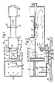
- Figure 1 is a plan view of a glass melting tank in accordance with the present invention,
- Figure 2 is a vertical section through the glass melting tank of Figure 1,
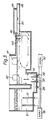
- Figure 3 is a view similar to Figure 2 of a different embodiment of the invention, and
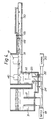
- Figure 4 is a view similar to Figure 2 of yet another embodiment of the invention, and
- Figure 5 is a graph showing temperature variation of forward flowing glass along the length of the tank shown in Figures 1 and 2.
- In this example the glass melting tank comprises a
melting chamber 11, arefining chamber 12 and aconditioning chamber 13. Ariser chamber 14 is locate between themelting chamber 11 and therefining chamber 12. The tank is suitable for use in producing high quality flat glass such as float glass. - In use solid batch material for producing glass is supplied through a system such as a hopper system to the top of the
melting chamber 11 so that a blanket ofsolid batch material 15 lies on top of molten glass 16 in the melting chamber. Heat is supplied to the melting chamber 16 by an array ofelectrodes 17 which are mounted on thebase 18 of the melting chamber and project vertically upwards so as to be immersed in the molten glass 16. Anelectrical supply 19 is connected to the electrode and controlled by acontrol unit 20. Molten glass flows out of themelting chamber 11 through a centrally locatedexit 21 in thebase 18 of the melting chamber adjacent adownstream wall 22 of the melting chamber. Theexit 21 leads to a submergedthroat 23 leading centrally into the lower part of theriser chamber 14. Athermocouple 24 is mounted in the base of thethroat 23 so as to detect the temperature of molten glass in thethroat 23. Thethermocouple 24 is connected to thecontrol unit 20. - The
riser chamber 14 is provided with an array ofelectrodes 25 which are mounted on abase 26 of the riser chamber and project vertically upwards so as to be immersed in the molten glass in the riser chamber. Theelectrodes 25 are arranged to increase the temperature of forward flowing glass so that on leaving theriser 14 the forward flowing glass is at a suitable refining temperature higher than the temperature of the glass entering through thethroat 23. Theelectrodes 25 are located in a central zone of theriser chamber 14 and are spaced from all four walls (upstream wall 28,downstream wall 29 andopposite side walls 30 and 31 of the riser chamber). In this way no heat is supplied to the molten glass in the riser chamber in the region of any of the walls of the chamber. Theelectrodes 25 are connected to thepower supply 19 and, like theelectrodes 17, are arranged to heat the molten glass by the Joule effect. Athermocouple 32 is mounted in thebase 26 of the riser chamber close to thedownstream wall 29 opposite thethroat 23 so as to detect the temperature of molten glass at the bottom of the riser chamber in the region close to thedownstream wall 29. Thethermocouple 32 is coupled to thecontrol unit 20 so as to control the power supplied to theelectrodes 25 in dependence on the temperature detected by thethermocouples control 20 provides control of the power supplied to theelectrode 25 in theriser chamber 14 independently of the control of the power supplied to theelectrode 17 in the melting zone 16. The walls of each chamber in the melting tank are formed of refractory material so as to withstand the molten glass in the tank. The arrangement in theriser chamber 14 is however arranged to minimise corrosion effects from glass passing through the riser chamber from the melting tank chamber 16 to therefining chamber 12. Theupstream wall 28 of the riser chamber is spaced fromwall 22 of the melting chamber so as to provide anair space 35 which acts as a cooling means for theupstream wall 28 of the riser chamber. Similarly thedownstream wall 29 of the riser chamber is separated by anair space 36 from theupstream wall 37 of therefining chamber 12. Thisair space 36 acts as a cooling means to cool thedownstream wall 29 of the riser chamber. The twoside walls 30 and 31 of the riser chamber are not facing heated chambers such as the melting and refining chambers and thereby permit sufficient cooling of the sides of the riser chamber. By arranging for theair spaces electrodes 25 so that the heat input in the riser chamber is confined to a central region well spaced from the side walls of the riser chamber, convective flows are formed in the glass passing through the riser chamber as shown in Figure 2. The result is a toroidal flow pattern in which glass in the central region of the riser chamber is caused to flow upwardly surrounded by an annular pattern of downwardly flowing glass adjacent the walls of the riser chamber. In this way, glass entering the riser chamber through thethroat 23 may rise in the central flow together with recirculated glass which has descended adjacent the walls of the riser chamber and then ascends in the central upward flow path. The glass which rises in the central region is then divided so that some passes over aweir 39 leading into therefining chamber 12 whereas the remainder is recirculated within the riser chamber in the toroidal pattern. By use of this system, the glass which flows forwardly over theweir 39 into the refining chamber has risen through the riser chamber out of contact with the refractory walls of the chamber and therefore has a much reduced likelihood of contamination from corrosion with the side walls. The glass which flows downwardly against the side walls is cooled by virtue of the cooling effect of theair spaces thermocouples electrodes 25 so as to ensure that there is no build-up of cold glass at the bottom of the riser chamber, particularly starting adjacent thedownstream wall 29. Any such build-up of colder glass could gradually restrict thethroat 23 causing the forward flowing glass to have a higher velocity on entering the riser chamber and thereby increasing the likelihood of corrosion at the foot of thewall 28 on entering the riser chamber. To minimise corrosion in the riser chamber it is important to avoid glass which enters from thethroat 23 rising immediately adjacent thewall 28. Due to the direction of flow through the glass melting tank as a whole the likelihood of corrosion in the riser chamber is greatest on the upstream anddownstream walls thermocouple 32 is used to ensure that the temperature of molten glass near the base of theriser 14 adjacent thedownstream wall 29 and opposite thethroat 23 is always higher than the temperature of the glass passing thethermocouple 24 in thethroat 23. To achieve the correct temperature distribution in theriser 14 theelectrodes 25 are arranged to input heat in the lower part of theriser chamber 14. The height of theelectrodes 25 is between 20% and 50%, preferably 30% and 40% of the depth of molten glass in theriser chamber 14. This provides sufficient heat input at the lower part of theriser chamber 14 to avoid a build up of cold glass at the bottom of thechamber 14. In a preferred arrangement, theelectrodes 25 are spaced from the walls of theriser chamber 14 by a distance at least as great as the height of theelectrodes 25. The lateral spacing between a pair ofelectrodes 25 may equal the sum of the width of thethroat 23 and the height of theelectrodes 25. The forward spacing between rows of theelectrode 25 may be between 0.8 and 1.4 times the height of theelectrodes 25. The ratio of the volume V of glass in theriser chamber 14 to the glass load L passing through the tank is preferably in the range 1.25 to 2.5 m³hr/tonne. The electrical power required in theriser chamber 14 is typically in therange 40 to 60 kw/m³. The power density for themolybdenum electrodes 25 is typically in therange 20 to 40 kw/dm³ of immersed molybdenum electrodes. - After passing over the
weir 39 into the refining chamber the molten glass is further heated so as to reduce contamination from impurities and also to release bubbles. The glass may recirculate as shown by the arrows in thechamber 12 so that the forward flowing glass is in the upper part of the refining chamber with a colder return flow at the bottom of the chamber. Additional heat is applied above the molten glass in theriser chamber 14 andrefining chamber 12 by gas burners operating through ports such as those marked at 40 and 41. - The glass melting tank is formed with a
waist 43 adjacent the junction between therefining chamber 12 andconditioning chamber 13. - A barrier in the form of a transverse water-cooled
pipe 44 extends across the waist and is submerged in the upper forward flowing path of the molten glass. The pipe is water-cooled so as to reduce the temperature of glass entering thethermal conditioning zone 13 and reduces the rate of flow of hot glass out of therefining chamber 12 thereby ensuring that the glass is held for a sufficient time in therefining chamber 12 for satisfactory refining to occur. The effect of thewater pipe 44 does cause some glass to flow downwardly at that point joining a return flow at the base to therefining chamber 12. An array ofstirrers 45 which may also be water-cooled are located adjacent thewater pipe 44 on the downstream side of the pipe. Thepipe 44 andstirrers 45 may improve the temperature and homogeneity of the glass entering theconditioning zone 13. Thezone 13 is not normally heated and the temperature of the glass is gradually reduced on flowing through theconditioning zone 13 towards anoutlet 48 leading to a glass forming process. Theoutlet 48 is positioned in the upper part of adownstream wall 49 of the conditioning zone so that only forward flowing glass in the upper part of theconditioning zone 13 leaves through theoutlet 48. The lower levels in the conditioning zone may be recirculated as a return flow at the lower part of the conditioning zone and passed back through the refining zone for further refinement before leaving through theoutlet 48. - As explained above, the
riser chamber 14 in this example is used to raise the temperature of forward flowing glass and is not used for controlled cooling. A graph showing the typical temperature pattern of forward flowing glass passing through the melting tank is shown in Figure 5. The temperature T1 of glass leaving themelting chamber 23 may fall slightly on passing through thethroat 23 and enter theriser chamber 14 at a temperature T2 insufficient for effective refining. The heat input in theriser chamber 14 exceeds the cooling effect so that the temperature T3 of glass leaving theriser chamber 14 over theweir 39 is at a suitable refining temperature higher than T2. On passing through therefining chamber 12 the forward flowing glass cools to temperature T4 but is always above T2 and sufficient to effect refining. On passing through thewaist 43 the temperature drops to T5 and controlled cooling to an outlet temperature T6 is effected on passing through theconditioning chamber 13. - The invention is not limited to the details of the foregoing example.
- In particular, the refining and conditioning zones of the unit may be designed to operate with various flow regimes in the molten glass.
- Alternatives to the above example are shown in Figure 3 and Figure 4. Figure 3 shows that the
downstream conditioning zone 50 is much shallower than therefining zone 12. This creates a situation in which there is only forward flow in the glass beyond thewaist 43. In this manner more efficient use can be made of the area available for conditioning e.g. to enable higher glass loading. Thedeeper refining zone 12 continues to operate with return flows in the glass generated by the cooling effects of the water-cooledbarrier 44 andstirrers 45 in the waist and of the refiner end wall. The amount of return flow is reduced compared with the full depth refining and conditioning and this produces greater thermal efficiency. - Figure 4 shows that the
refining zone 51,waist 43 andconditioning zone 50 are all of a similar shallow depth to that illustrated by Figure 3. Under these conditions, there is only forward flow present in the glass beyond theriser zone 14. This reduces the energy requirement by virtue of not having to reheat return flows. Thewaist section 43 retains ashallow water pipe 44 to impede the surface flow leaving the refining zone. Therefining zone 51 can be heated either by above-glass burners 41 or by below glass electric heating or by a combination of the two methods. - It will further be understood that, if desired, molten glass could be fed to the riser chamber through a plurality of throats, for example from a plurality of melting chambers. Such throats may be through different walls of the riser chamber which need not be of rectangular form and could have a number of walls other than four. A plurality of
riser chambers 14 may be provided each supplied by a respective throat. A plurality of risers may be used and may be connected to a common conditioning chamber.
Claims (24)
Applications Claiming Priority (2)
| Application Number | Priority Date | Filing Date | Title |
|---|---|---|---|
| GB8913539 | 1989-06-13 | ||
| GB898913539A GB8913539D0 (en) | 1989-06-13 | 1989-06-13 | Glass melting |
Publications (3)
| Publication Number | Publication Date |
|---|---|
| EP0403184A2 true EP0403184A2 (en) | 1990-12-19 |
| EP0403184A3 EP0403184A3 (en) | 1992-03-04 |
| EP0403184B1 EP0403184B1 (en) | 1995-04-05 |
Family
ID=10658340
Family Applications (2)
| Application Number | Title | Priority Date | Filing Date |
|---|---|---|---|
| EP90306288A Expired - Lifetime EP0403184B1 (en) | 1989-06-13 | 1990-06-08 | Glass melting |
| EP19900306287 Withdrawn EP0403183A3 (en) | 1989-06-13 | 1990-06-08 | Glass melting |
Family Applications After (1)
| Application Number | Title | Priority Date | Filing Date |
|---|---|---|---|
| EP19900306287 Withdrawn EP0403183A3 (en) | 1989-06-13 | 1990-06-08 | Glass melting |
Country Status (28)
| Country | Link |
|---|---|
| EP (2) | EP0403184B1 (en) |
| JP (1) | JPH07106913B2 (en) |
| KR (1) | KR0129770B1 (en) |
| CN (1) | CN1022905C (en) |
| AR (1) | AR243485A1 (en) |
| AT (1) | ATE120723T1 (en) |
| AU (1) | AU632331B2 (en) |
| BG (1) | BG60861B1 (en) |
| BR (1) | BR9002798A (en) |
| CA (1) | CA2018740C (en) |
| CZ (1) | CZ285223B6 (en) |
| DD (1) | DD298373A5 (en) |
| DE (1) | DE69018317T2 (en) |
| ES (1) | ES2073527T3 (en) |
| FI (1) | FI91520C (en) |
| GB (3) | GB8913539D0 (en) |
| HU (1) | HU215945B (en) |
| IE (1) | IE67772B1 (en) |
| IN (1) | IN175675B (en) |
| NO (1) | NO178658C (en) |
| NZ (1) | NZ234012A (en) |
| PL (1) | PL166463B1 (en) |
| PT (1) | PT94349B (en) |
| RO (1) | RO106124B1 (en) |
| RU (1) | RU1838253C (en) |
| TR (1) | TR27116A (en) |
| YU (1) | YU47355B (en) |
| ZA (1) | ZA904578B (en) |
Cited By (2)
| Publication number | Priority date | Publication date | Assignee | Title |
|---|---|---|---|---|
| US6339610B1 (en) | 1999-05-28 | 2002-01-15 | Schott Glas | Glass melting tank and process for melting glass |
| CN103359911A (en) * | 2012-04-05 | 2013-10-23 | 安瀚视特控股株式会社 | Making method of glass substrate |
Families Citing this family (19)
| Publication number | Priority date | Publication date | Assignee | Title |
|---|---|---|---|---|
| DE4424951C2 (en) * | 1994-07-14 | 1997-07-10 | Flachglas Ag | Method and device for vitrifying residues |
| US6506792B1 (en) | 1997-03-04 | 2003-01-14 | Sterix Limited | Compounds that inhibit oestrone sulphatase and/or aromatase and methods for making and using |
| JP2001515453A (en) * | 1998-01-09 | 2001-09-18 | サン−ゴバン ビトラージュ | Method for melting and refining vitrizable substances |
| FR2787784B1 (en) * | 1998-12-23 | 2001-04-20 | Stein Heurtey | IMPROVEMENTS TO GLASS MELTING AND REFINING OVENS |
| KR20020046075A (en) * | 2000-12-12 | 2002-06-20 | 곽영훈 | Glass Furnace |
| KR20030005482A (en) * | 2001-07-09 | 2003-01-23 | 김명식 | Electric furnace for manufacturing glass and method for manufacturing glass using the electric furmace |
| CN1902045B (en) * | 2003-11-28 | 2011-04-13 | 康宁股份有限公司 | Method of fabricating low-warp flat glass |
| US7854144B2 (en) * | 2005-07-28 | 2010-12-21 | Corning Incorporated | Method of reducing gaseous inclusions in a glass making process |
| US7454925B2 (en) * | 2005-12-29 | 2008-11-25 | Corning Incorporated | Method of forming a glass melt |
| CN101838098B (en) * | 2010-03-30 | 2013-02-13 | 株洲旗滨集团股份有限公司 | Novel oxy-fuel combustion glass melting furnace |
| JP5719797B2 (en) * | 2012-04-06 | 2015-05-20 | AvanStrate株式会社 | Glass plate manufacturing method and glass plate manufacturing apparatus |
| JP5731437B2 (en) * | 2012-04-06 | 2015-06-10 | AvanStrate株式会社 | Manufacturing method of glass plate |
| JP6418455B2 (en) * | 2013-01-24 | 2018-11-07 | コーニング インコーポレイテッド | Process and apparatus for clarifying molten glass |
| JP6749123B2 (en) * | 2016-03-31 | 2020-09-02 | AvanStrate株式会社 | Glass substrate manufacturing method and glass substrate manufacturing apparatus |
| EP3760595A1 (en) * | 2019-07-04 | 2021-01-06 | International Partners in Glass Research (IPGR) e.V. | Glass melting furnace |
| KR102172552B1 (en) * | 2020-06-26 | 2020-11-02 | 이준호 | Direct heating type melting device using heat exchange system |
| JP2022088071A (en) * | 2020-12-02 | 2022-06-14 | 日本電気硝子株式会社 | Glass melting furnace monitoring method and glass article manufacturing method |
| DE102022110617A1 (en) | 2022-05-02 | 2023-11-02 | Saint-Gobain SEKURIT Deutschland GmbH | Process for producing hydrogen in a hydrogen-operated glass melting tank |
| EP4345069A1 (en) * | 2023-09-29 | 2024-04-03 | Schott Ag | A vessel system for producing and refining a glass melt, and method for producing and refining a glass melt |
Citations (4)
| Publication number | Priority date | Publication date | Assignee | Title |
|---|---|---|---|---|
| GB1480935A (en) * | 1974-01-25 | 1977-07-27 | Sorg Gmbh & Co N | Method of dyeing and treating glass streams |
| US4693740A (en) * | 1983-08-09 | 1987-09-15 | Saint-Gobain Vitrage | Process and device for melting, fining and homogenizing glass |
| DE3718276A1 (en) * | 1987-05-30 | 1988-12-08 | Sorg Gmbh & Co Kg | GLASS MELTING STOVE |
| EP0304371A1 (en) * | 1987-08-18 | 1989-02-22 | Saint-Gobain Vitrage International | Method and apparatus for making molten glass |
Family Cites Families (8)
| Publication number | Priority date | Publication date | Assignee | Title |
|---|---|---|---|---|
| BE390369A (en) * | 1932-05-05 | |||
| BE409868A (en) * | 1934-06-13 | |||
| GB822818A (en) * | 1956-05-14 | 1959-11-04 | Libbey Owens Ford Glass Co | Method and apparatus for melting glass |
| FR1502663A (en) * | 1966-05-17 | 1967-11-24 | Saint Gobain | Glass manufacturing process |
| US4424071A (en) * | 1982-09-27 | 1984-01-03 | Toledo Engineering Co., Inc. | Molten mass temperature conditioner |
| DD216710A1 (en) * | 1983-07-06 | 1984-12-19 | Inst Techn Glas Jena Veb | GLASS MELTING PAN |
| WO1985001497A1 (en) * | 1983-09-29 | 1985-04-11 | Owens-Corning Fiberglas Corporation | Electrical melting of solidified glass in melting units |
| FR2599734B1 (en) * | 1986-06-06 | 1992-06-05 | Saint Gobain Rech | ELECTRIC GLASS FUSION TECHNIQUE |
-
1989
- 1989-06-13 GB GB898913539A patent/GB8913539D0/en active Pending
-
1990
- 1990-06-06 IE IE203390A patent/IE67772B1/en not_active IP Right Cessation
- 1990-06-07 TR TR00555/90A patent/TR27116A/en unknown
- 1990-06-08 GB GB9012836A patent/GB2232753A/en not_active Withdrawn
- 1990-06-08 ES ES90306288T patent/ES2073527T3/en not_active Expired - Lifetime
- 1990-06-08 AU AU57040/90A patent/AU632331B2/en not_active Ceased
- 1990-06-08 AT AT90306288T patent/ATE120723T1/en not_active IP Right Cessation
- 1990-06-08 DE DE69018317T patent/DE69018317T2/en not_active Expired - Fee Related
- 1990-06-08 GB GB9012835A patent/GB2235445A/en not_active Withdrawn
- 1990-06-08 EP EP90306288A patent/EP0403184B1/en not_active Expired - Lifetime
- 1990-06-08 EP EP19900306287 patent/EP0403183A3/en not_active Withdrawn
- 1990-06-11 NO NO902572A patent/NO178658C/en unknown
- 1990-06-11 NZ NZ234012A patent/NZ234012A/en unknown
- 1990-06-11 CA CA002018740A patent/CA2018740C/en not_active Expired - Fee Related
- 1990-06-12 HU HU903819A patent/HU215945B/en not_active IP Right Cessation
- 1990-06-12 IN IN457MA1990 patent/IN175675B/en unknown
- 1990-06-12 AR AR90317076A patent/AR243485A1/en active
- 1990-06-12 CN CN90104312A patent/CN1022905C/en not_active Expired - Fee Related
- 1990-06-12 BG BG92205A patent/BG60861B1/en unknown
- 1990-06-12 YU YU114090A patent/YU47355B/en unknown
- 1990-06-12 DD DD90341562A patent/DD298373A5/en not_active IP Right Cessation
- 1990-06-12 RU SU904830236A patent/RU1838253C/en active
- 1990-06-12 PT PT94349A patent/PT94349B/en not_active IP Right Cessation
- 1990-06-12 KR KR1019900008580A patent/KR0129770B1/en not_active IP Right Cessation
- 1990-06-13 CZ CS902939A patent/CZ285223B6/en unknown
- 1990-06-13 FI FI902962A patent/FI91520C/en not_active IP Right Cessation
- 1990-06-13 RO RO145335A patent/RO106124B1/en unknown
- 1990-06-13 PL PL90285637A patent/PL166463B1/en unknown
- 1990-06-13 ZA ZA904578A patent/ZA904578B/en unknown
- 1990-06-13 BR BR909002798A patent/BR9002798A/en not_active IP Right Cessation
- 1990-06-13 JP JP2154986A patent/JPH07106913B2/en not_active Expired - Fee Related
Patent Citations (4)
| Publication number | Priority date | Publication date | Assignee | Title |
|---|---|---|---|---|
| GB1480935A (en) * | 1974-01-25 | 1977-07-27 | Sorg Gmbh & Co N | Method of dyeing and treating glass streams |
| US4693740A (en) * | 1983-08-09 | 1987-09-15 | Saint-Gobain Vitrage | Process and device for melting, fining and homogenizing glass |
| DE3718276A1 (en) * | 1987-05-30 | 1988-12-08 | Sorg Gmbh & Co Kg | GLASS MELTING STOVE |
| EP0304371A1 (en) * | 1987-08-18 | 1989-02-22 | Saint-Gobain Vitrage International | Method and apparatus for making molten glass |
Cited By (3)
| Publication number | Priority date | Publication date | Assignee | Title |
|---|---|---|---|---|
| US6339610B1 (en) | 1999-05-28 | 2002-01-15 | Schott Glas | Glass melting tank and process for melting glass |
| CN103359911A (en) * | 2012-04-05 | 2013-10-23 | 安瀚视特控股株式会社 | Making method of glass substrate |
| CN103359911B (en) * | 2012-04-05 | 2015-12-23 | 安瀚视特控股株式会社 | The manufacture method of glass substrate |
Also Published As
Similar Documents
| Publication | Publication Date | Title |
|---|---|---|
| EP0403184B1 (en) | Glass melting | |
| US5194081A (en) | Glass melting process | |
| US4046546A (en) | Method and apparatus for refining glass in a melting tank | |
| US6085551A (en) | Method and apparatus for manufacturing high melting point glasses with volatile components | |
| EP0120050B1 (en) | Molten mass temperature conditioner | |
| EP0186972B1 (en) | Improvements in or relating to glass melting tanks and to refractory materials for use therein | |
| US5370723A (en) | Glass melting furnace with control of the glass flow in the riser | |
| US4906272A (en) | Furnace for fining molten glass | |
| US4528013A (en) | Melting furnaces | |
| US4200448A (en) | Glass manufacture | |
| US4994099A (en) | Method for fining molten glass | |
| US4052186A (en) | Method and apparatus for conditioning molten glass | |
| US4317669A (en) | Glass melting furnace having a submerged weir | |
| US4082528A (en) | Glass melting tank with temperature control and method of melting | |
| HRP920861A2 (en) | Glass melting | |
| KR800000199B1 (en) | Manufacturing device for glass | |
| IE42253B1 (en) | Thermally conditioning molten glass | |
| IE42255B1 (en) | Improvements in or relating to refining molten glass |
Legal Events
| Date | Code | Title | Description |
|---|---|---|---|
| PUAI | Public reference made under article 153(3) epc to a published international application that has entered the european phase |
Free format text: ORIGINAL CODE: 0009012 |
|
| AK | Designated contracting states |
Kind code of ref document: A2 Designated state(s): AT BE CH DE DK ES FR GB GR IT LI LU NL SE |
|
| PUAL | Search report despatched |
Free format text: ORIGINAL CODE: 0009013 |
|
| AK | Designated contracting states |
Kind code of ref document: A3 Designated state(s): AT BE CH DE DK ES FR GB GR IT LI LU NL SE |
|
| 17P | Request for examination filed |
Effective date: 19920901 |
|
| 17Q | First examination report despatched |
Effective date: 19930524 |
|
| GRAA | (expected) grant |
Free format text: ORIGINAL CODE: 0009210 |
|
| AK | Designated contracting states |
Kind code of ref document: B1 Designated state(s): AT BE CH DE DK ES FR GB GR IT LI LU NL SE |
|
| PG25 | Lapsed in a contracting state [announced via postgrant information from national office to epo] |
Ref country code: LI Effective date: 19950405 Ref country code: GR Free format text: LAPSE BECAUSE OF FAILURE TO SUBMIT A TRANSLATION OF THE DESCRIPTION OR TO PAY THE FEE WITHIN THE PRESCRIBED TIME-LIMIT Effective date: 19950405 Ref country code: DK Effective date: 19950405 Ref country code: CH Effective date: 19950405 Ref country code: AT Effective date: 19950405 |
|
| REF | Corresponds to: |
Ref document number: 120723 Country of ref document: AT Date of ref document: 19950415 Kind code of ref document: T |
|
| ITF | It: translation for a ep patent filed |
Owner name: JACOBACCI & PERANI S.P.A. |
|
| REF | Corresponds to: |
Ref document number: 69018317 Country of ref document: DE Date of ref document: 19950511 |
|
| ET | Fr: translation filed | ||
| REG | Reference to a national code |
Ref country code: CH Ref legal event code: PL |
|
| REG | Reference to a national code |
Ref country code: ES Ref legal event code: FG2A Ref document number: 2073527 Country of ref document: ES Kind code of ref document: T3 |
|
| PLBE | No opposition filed within time limit |
Free format text: ORIGINAL CODE: 0009261 |
|
| STAA | Information on the status of an ep patent application or granted ep patent |
Free format text: STATUS: NO OPPOSITION FILED WITHIN TIME LIMIT |
|
| 26N | No opposition filed | ||
| PGFP | Annual fee paid to national office [announced via postgrant information from national office to epo] |
Ref country code: SE Payment date: 19970522 Year of fee payment: 8 |
|
| PGFP | Annual fee paid to national office [announced via postgrant information from national office to epo] |
Ref country code: LU Payment date: 19970710 Year of fee payment: 8 |
|
| PGFP | Annual fee paid to national office [announced via postgrant information from national office to epo] |
Ref country code: GB Payment date: 19980601 Year of fee payment: 9 |
|
| PG25 | Lapsed in a contracting state [announced via postgrant information from national office to epo] |
Ref country code: LU Free format text: LAPSE BECAUSE OF NON-PAYMENT OF DUE FEES Effective date: 19980608 |
|
| PG25 | Lapsed in a contracting state [announced via postgrant information from national office to epo] |
Ref country code: SE Free format text: LAPSE BECAUSE OF NON-PAYMENT OF DUE FEES Effective date: 19980609 |
|
| PGFP | Annual fee paid to national office [announced via postgrant information from national office to epo] |
Ref country code: FR Payment date: 19980609 Year of fee payment: 9 |
|
| PGFP | Annual fee paid to national office [announced via postgrant information from national office to epo] |
Ref country code: DE Payment date: 19980612 Year of fee payment: 9 |
|
| PGFP | Annual fee paid to national office [announced via postgrant information from national office to epo] |
Ref country code: ES Payment date: 19980619 Year of fee payment: 9 |
|
| PGFP | Annual fee paid to national office [announced via postgrant information from national office to epo] |
Ref country code: NL Payment date: 19980629 Year of fee payment: 9 |
|
| PGFP | Annual fee paid to national office [announced via postgrant information from national office to epo] |
Ref country code: BE Payment date: 19980813 Year of fee payment: 9 |
|
| EUG | Se: european patent has lapsed |
Ref document number: 90306288.3 |
|
| PG25 | Lapsed in a contracting state [announced via postgrant information from national office to epo] |
Ref country code: GB Free format text: LAPSE BECAUSE OF NON-PAYMENT OF DUE FEES Effective date: 19990608 |
|
| PG25 | Lapsed in a contracting state [announced via postgrant information from national office to epo] |
Ref country code: ES Free format text: LAPSE BECAUSE OF NON-PAYMENT OF DUE FEES Effective date: 19990609 |
|
| PG25 | Lapsed in a contracting state [announced via postgrant information from national office to epo] |
Ref country code: FR Free format text: THE PATENT HAS BEEN ANNULLED BY A DECISION OF A NATIONAL AUTHORITY Effective date: 19990630 Ref country code: BE Free format text: LAPSE BECAUSE OF NON-PAYMENT OF DUE FEES Effective date: 19990630 |
|
| BERE | Be: lapsed |
Owner name: PILKINGTON P.L.C. Effective date: 19990630 |
|
| PG25 | Lapsed in a contracting state [announced via postgrant information from national office to epo] |
Ref country code: NL Free format text: LAPSE BECAUSE OF NON-PAYMENT OF DUE FEES Effective date: 20000101 |
|
| GBPC | Gb: european patent ceased through non-payment of renewal fee |
Effective date: 19990608 |
|
| NLV4 | Nl: lapsed or anulled due to non-payment of the annual fee |
Effective date: 20000101 |
|
| PG25 | Lapsed in a contracting state [announced via postgrant information from national office to epo] |
Ref country code: DE Free format text: LAPSE BECAUSE OF NON-PAYMENT OF DUE FEES Effective date: 20000503 |
|
| REG | Reference to a national code |
Ref country code: FR Ref legal event code: ST |
|
| REG | Reference to a national code |
Ref country code: ES Ref legal event code: FD2A Effective date: 20010503 |
|
| PG25 | Lapsed in a contracting state [announced via postgrant information from national office to epo] |
Ref country code: IT Free format text: LAPSE BECAUSE OF NON-PAYMENT OF DUE FEES;WARNING: LAPSES OF ITALIAN PATENTS WITH EFFECTIVE DATE BEFORE 2007 MAY HAVE OCCURRED AT ANY TIME BEFORE 2007. THE CORRECT EFFECTIVE DATE MAY BE DIFFERENT FROM THE ONE RECORDED. Effective date: 20050608 |