EP0402618A2 - Potentiomètre à rotation avec corps de rotation et mécanisme de commande - Google Patents
Potentiomètre à rotation avec corps de rotation et mécanisme de commande Download PDFInfo
- Publication number
- EP0402618A2 EP0402618A2 EP90108617A EP90108617A EP0402618A2 EP 0402618 A2 EP0402618 A2 EP 0402618A2 EP 90108617 A EP90108617 A EP 90108617A EP 90108617 A EP90108617 A EP 90108617A EP 0402618 A2 EP0402618 A2 EP 0402618A2
- Authority
- EP
- European Patent Office
- Prior art keywords
- pins
- rotating body
- rotary potentiometer
- shaft
- axis
- Prior art date
- Legal status (The legal status is an assumption and is not a legal conclusion. Google has not performed a legal analysis and makes no representation as to the accuracy of the status listed.)
- Granted
Links
Images

Classifications
-
- H—ELECTRICITY
- H01—ELECTRIC ELEMENTS
- H01C—RESISTORS
- H01C10/00—Adjustable resistors
- H01C10/14—Adjustable resistors adjustable by auxiliary driving means
Definitions
- the invention relates to a rotary potentiometer with a rotating body which carries sliding contacts on its rear side and two pins on one end, the axes of which lie parallel to the axis of rotation of the rotating body and are arranged opposite one another with respect to the axis of rotation, - And with a drive device, consisting of a fixed to a shaft rotatable concentrically to the axis of rotation of the shaft, which strikes with its ends on the outside in a contact area of a pin and thus can transmit torque from the shaft to the rotating body.
- Such a rotary potentiometer is known for example from DE-GM 80 10 175.
- the rotary body is arranged inside a housing.
- the pins are located inside the housing and the bar, which is part of the drive device, engages in the housing. It must be assumed that the drive device with the bar opposite the pin must have a certain amount of play in the axial direction of the rotating body axis, since the drive device is connected to parts, for example an internal combustion engine, which always have a certain amount with respect to the potentiometer via vibrations, thermal expansion and the like Make movement so that such a game is essential.
- the game leads to abrasion, loosening and adjustments, which permanently influence the exact setting of the potentiometer and lead to incorrect settings. Since such rotary potentiometers are used, for example, with the throttle valve of electronically monitored carburettors, it is very important that an adjustment over the life of the engine is practically impossible, or at least can be corrected. In addition, it is necessary that a precise setting and adjustment (calibration) can be carried out before the rotary potentiometer is delivered, the time required for this being kept as short as possible.
- the bar does not protrude into the interior of a housing, but contacts the pins outside of a housing.
- a rotary potentiometer with this arrangement has a very long service life; Contamination does not affect the contact area between the peg and the beam.
- the contact area between the pin and the drive device remains accessible and can be adjusted subsequently with suitable measures, some of which are shown as exemplary embodiments in the subclaims.
- An essential embodiment is the one in which the rotating body consists of a shaft and a turntable, which are connected coaxially one behind the other, and in which the shaft ends at its free end in the end face carrying the pins and the rotating disk carries the sliding contacts.
- the turntable is preferably surrounded by the housing, which is provided with a guide opening through which the free end of the shaft of the rotary body protrudes and in which it is preferably also guided.
- the accessibility of the connection between the pin and the beam in the installed, or at least the assembled state makes it possible to provide various adjustment options.
- the beam can be given a wedge shape.
- the bar can then be guided in an elongated hole along the axis of rotation of its shaft, wherein certain initial angles of rotation can be compensated within the given adjustment possibilities.
- At least one of the pins on the end face of the rotating body can be adjustable on a line lying parallel or tangential to a rotating circle.
- the adjustability can advantageously also be achieved in that the pins are arranged on a ring which surrounds the rotating body or the shaft and is rotatable.
- At least one of the pins has eccentricities in the contact area with the bar, so that the distance of the contact area from the axis can be adjusted when the pin is rotated about its axis. This also makes it possible to adjust the starting angle of the rotary potentiometer.
- the slot gives the possibility to twist the pin with a screwdriver or to bend it open slightly so that the adjustment possibility is achieved.
- the above possibilities of adjusting the contact areas with respect to a zero position of the potentiometer can preferably be achieved if the pins on the end face of the rotating body are freely accessible from the periphery of the end face.
- the housing also partially encloses the end face, but still leaves sufficient access to adjust the pins and / or the beams in the aforementioned manner, at least when removed.
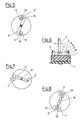
- FIG. 1 shows a rotary potentiometer in which a turntable 31 is arranged in a housing 11 and has a sliding contact 32 on its rear side 2.
- the turntable 31 is integrally connected to a shaft 33, so that the two parts 32 and 33 lie one behind the other, are connected coaxially and form a rotating body 1.
- the free end 34 of the shaft 33 protrudes from the housing 11 and ends in a flat end face 10.
- the shaft 33 is guided in a guide opening 35 in the housing 11, which completely surrounds the turntable 31.
- the pins can be made of metal, while the rotating body 10 is made, for example, of a non-conductive material, such as plastic or ceramic. To reduce wear, pins and beams in the contact areas can be covered with a low-wear metal, for example polished stainless steel.
- the two pins 3, 4 are offset by an angle of 180 ° about a rotating circle running around the axis of rotation 5, in other words, they are in relation to one another the axis of rotation 5 opposite each other.
- a drive device 6 which consists of a shaft 7 which can be rotated concentrically to the axis of rotation of the rotating body and a beam 8 fastened thereon, projects into the working area limited by the height of the pins.
- the ends of the beam 8 strike one outside in a contact area 9 on the outside of one pin 3, 4 each.
- a torque can be transmitted from the shaft 7 to the rotating body 1 in the counterclockwise direction according to FIG.
- the pins 3, 4 are not exactly round, but have 8 eccentricities 14 in the contact area 9 with the bar.
- the pins 3, 4 are rotatable about their axis, so that when the pins 3, 4 are rotated about their axis, the distance of the contact area 9 from the axis of the pin 15 is adjustable.
- This adjustment can be achieved, for example, in that the pins are somewhat roughened outside the contact area, have a puncture for attaching a tool, or have similar properties.
- This adjustment option also ensures that adjustments to the axis of rotation 5 of the rotating body relative to the shaft 7 can be compensated for after installation.
- the housing 11 does not protrude beyond the region of the pins 3, 4, but rather allows the end face 10 of the shaft 33 to be freely accessible from the periphery. So that the necessary game between bar 8 and pin height is unaffected and can even be easily checked from the outside.
- Figure 3 shows a top view of an embodiment in which there are round pins 3 ′′′ and 4 ′′′ on a ring 36 surrounding the rotating body or the shaft 33, which is rotatably adjustable against a frictional force, so that with it the positions of the pins 3 ′′′ and 4 ′′′ is adjustable relative to the bar position.
- Figure 3a shows an embodiment in which the beam 8 cooperates with two pins 3 ′′′ and 4 ′′′, which are implanted in the end face 10 so that they are adjustable on a line 25 lying parallel or tangent to a rotating circle.
- This can be done, for example, in that a slot 25 'is milled into the end face, which receives the foot of the pin 3 ′′′ or 4 ′′′, the foot being held in a form-fitting manner.
- the adjustment range only extends over a short distance, for example over the diameter of the pin in question.
- a rotary potentiometer in which in a housing 11, a rotating body 1 is rotatably arranged about an axis of rotation 5, which projects with an axle stub 5 'down through the housing 11. It is an essentially disk-shaped rotating body 1, which has 2 sliding contacts on its back, which are not shown in detail in the present case.
- the resistance is changed, as is customary in the potentiometer principle.
- two pins 3, 4 are firmly implanted or are produced in one piece with the rotary body.
- the pins can be made of metal, while the rotating body 10 is made, for example, of a non-conductive material, such as plastic or ceramic.
- pins and beams can be used in contact areas with a low-wear metal, for example white polished stainless steel.
- the two pins 3, 4 are offset by an angle of 180 ° about a rotating circle running about the axis of rotation 5, in other words, they are opposite one another with respect to the axis of rotation 5.
- a drive device 6, which consists of a shaft 7 which can be rotated concentrically to the axis of rotation of the rotating body and a beam 8 fastened thereon, projects into the working area delimited by the height of the pins.
- the ends of the beam 8 strike one outside in a contact area 9 on the outside of one pin 3, 4 each.
- a torque can be transmitted from the shaft 7 to the rotating body 1 in the counterclockwise direction according to FIG.
- Figure 5 shows an embodiment in which pins 3 ⁇ , 4 ⁇ are provided, which also have eccentricities 14 ', namely opposite, and additionally carry a slot 16 which over part of the height of the pins 3 ⁇ and 4 ⁇ enough.
- the eccentricities are not achieved by additional material thickenings, but by the fact that two bendable tongues 17, 18 limit the slot 16 and are bent apart with a wedge-shaped tool. This also allows the setting angle of the potentiometer setting to be adjusted.
- a bar 8 ' is provided, which is adjustable relative to the shaft 7 in the longitudinal direction of the bar, as indicated by the arrows (solid, dashed).
- the bar 8 ' With the help of an elongated hole guide 15 and, for example, a clamping device, the bar 8 'can be adjusted relative to the shaft 7 as required.
- the bar 8 ' In order to achieve a change in the approach angle of rotation (zero angle) with the adjustment, the bar 8 'has a wedge shape, so that there are changed angles of attack.
- Figure 8 shows a further embodiment in which a beam 8 ⁇ is provided which has a slot 20, 21 from its two free ends, the tongues delimiting the slots 22, 23 also being able to be bent apart, so that the angle of attack relative to the Pins 3 ', 4' can change.
Landscapes
- Engineering & Computer Science (AREA)
- Microelectronics & Electronic Packaging (AREA)
- Adjustable Resistors (AREA)
Applications Claiming Priority (2)
| Application Number | Priority Date | Filing Date | Title |
|---|---|---|---|
| DE8907174U DE8907174U1 (de) | 1989-06-12 | 1989-06-12 | Drehpotentiometer mit Drehkörper und Antriebsvorrichtung |
| DE8907174U | 1989-06-12 |
Publications (3)
| Publication Number | Publication Date |
|---|---|
| EP0402618A2 true EP0402618A2 (fr) | 1990-12-19 |
| EP0402618A3 EP0402618A3 (fr) | 1991-04-24 |
| EP0402618B1 EP0402618B1 (fr) | 1995-03-29 |
Family
ID=6840015
Family Applications (1)
| Application Number | Title | Priority Date | Filing Date |
|---|---|---|---|
| EP90108617A Expired - Lifetime EP0402618B1 (fr) | 1989-06-12 | 1990-05-08 | Potentiomètre à rotation avec corps de rotation et mécanisme de commande |
Country Status (2)
| Country | Link |
|---|---|
| EP (1) | EP0402618B1 (fr) |
| DE (2) | DE8907174U1 (fr) |
Cited By (1)
| Publication number | Priority date | Publication date | Assignee | Title |
|---|---|---|---|---|
| CN115394510A (zh) * | 2022-10-31 | 2022-11-25 | 成都宏明电子股份有限公司 | 导电塑料角位移电位器用高寿命电阻体的制造方法 |
Family Cites Families (3)
| Publication number | Priority date | Publication date | Assignee | Title |
|---|---|---|---|---|
| DE3444229A1 (de) * | 1984-11-30 | 1986-06-05 | Preh, Elektrofeinmechanische Werke Jakob Preh Nachf. Gmbh & Co, 8740 Bad Neustadt | Einstellbarer widerstand |
| DE3612574C1 (de) * | 1986-04-15 | 1987-06-19 | Preh Elektro Feinmechanik | Antriebseinrichtung eines Drehpotentiometers |
| DE3624640A1 (de) * | 1986-07-22 | 1988-01-28 | Ruf Kg Wilhelm | Drehpotentiometer, insbesondere zur verwendung als drehstellungsmessfuehler fuer die drehstellung einer welle |
-
1989
- 1989-06-12 DE DE8907174U patent/DE8907174U1/de not_active Expired
-
1990
- 1990-05-08 EP EP90108617A patent/EP0402618B1/fr not_active Expired - Lifetime
- 1990-05-08 DE DE59008788T patent/DE59008788D1/de not_active Expired - Fee Related
Cited By (2)
| Publication number | Priority date | Publication date | Assignee | Title |
|---|---|---|---|---|
| CN115394510A (zh) * | 2022-10-31 | 2022-11-25 | 成都宏明电子股份有限公司 | 导电塑料角位移电位器用高寿命电阻体的制造方法 |
| CN115394510B (zh) * | 2022-10-31 | 2023-02-14 | 成都宏明电子股份有限公司 | 导电塑料角位移电位器用高寿命电阻体的制造方法 |
Also Published As
| Publication number | Publication date |
|---|---|
| DE59008788D1 (de) | 1995-05-04 |
| DE8907174U1 (de) | 1989-09-28 |
| EP0402618B1 (fr) | 1995-03-29 |
| EP0402618A3 (fr) | 1991-04-24 |
Similar Documents
| Publication | Publication Date | Title |
|---|---|---|
| DE3509787C2 (de) | Chirurgisches Instrument zum Spreizen von Wundrändern | |
| AT522446B1 (de) | Möbelantrieb | |
| EP0308666A1 (fr) | Tête de lame pour hachoir | |
| DE19600031C2 (de) | Vertikal einstellbarer Maschinenträger | |
| DE2106671C3 (de) | Vorrichtung zum Schärfen von Bohrerspitzen, insbesondere von Spiralbohrern | |
| DE202011000688U1 (de) | Vorrichtung zur Aufnahme von Filtern für Mikroskope | |
| DE9205733U1 (de) | Schlauchpumpe | |
| DE2420636B2 (de) | Lagerung für einen Spiegelglasträger eines fernverstellbaren Fahrzeugrückblickspiegels | |
| EP0525507B1 (fr) | Dispositif de réglage d'un actionneur pour régler la cylindrée d'une machine hydrostatique | |
| EP0087623A1 (fr) | Procédé d'assemblage d'une vis-mère double montée sur une broche filetée | |
| EP0141283A1 (fr) | Cylindre rotatif garni d'aiguilles pour machines textiles | |
| EP0402618B1 (fr) | Potentiomètre à rotation avec corps de rotation et mécanisme de commande | |
| DE3005854C2 (fr) | ||
| DE4415134C2 (de) | Drehstellungs-Anzeigevorrichtung | |
| EP3488972B1 (fr) | Dispositif de pivotement | |
| DE102020105709A1 (de) | Linearsystem und Verfahren zur Montage solch eines Linearsystems | |
| EP1637771A2 (fr) | Dispositif d'entraînement à éléments filetés | |
| DE2308287B2 (de) | Vorrichtung zur Drehwinkeleinstellung eines Werkstückes | |
| CH553903A (de) | Vorrichtung zum arretieren eines eine oeffnung verschliessenden elementes. | |
| DE2729560C3 (de) | Einrichtung zum Fixieren eines Steuerschiebers | |
| EP0849046B1 (fr) | Mécanisme d'actionnement | |
| DE202007017951U1 (de) | Gehäuse mit einer darin angeordneten Baugruppe | |
| DE69609556T2 (de) | Vorrichtung zur Anzeige von Abbildungen, Texten und dergleichen | |
| DE4429083C2 (de) | Dehnschraube für Zahnregulierungen | |
| DE19627763A1 (de) | Antriebsverbindung |
Legal Events
| Date | Code | Title | Description |
|---|---|---|---|
| PUAI | Public reference made under article 153(3) epc to a published international application that has entered the european phase |
Free format text: ORIGINAL CODE: 0009012 |
|
| AK | Designated contracting states |
Kind code of ref document: A2 Designated state(s): DE FR GB IT |
|
| PUAL | Search report despatched |
Free format text: ORIGINAL CODE: 0009013 |
|
| AK | Designated contracting states |
Kind code of ref document: A3 Designated state(s): DE FR GB IT |
|
| 17P | Request for examination filed |
Effective date: 19911023 |
|
| 17Q | First examination report despatched |
Effective date: 19931027 |
|
| GRAA | (expected) grant |
Free format text: ORIGINAL CODE: 0009210 |
|
| AK | Designated contracting states |
Kind code of ref document: B1 Designated state(s): DE FR GB IT |
|
| GBT | Gb: translation of ep patent filed (gb section 77(6)(a)/1977) |
Effective date: 19950327 |
|
| PGFP | Annual fee paid to national office [announced via postgrant information from national office to epo] |
Ref country code: GB Payment date: 19950504 Year of fee payment: 6 |
|
| REF | Corresponds to: |
Ref document number: 59008788 Country of ref document: DE Date of ref document: 19950504 |
|
| ITF | It: translation for a ep patent filed | ||
| PGFP | Annual fee paid to national office [announced via postgrant information from national office to epo] |
Ref country code: FR Payment date: 19950518 Year of fee payment: 6 |
|
| ET | Fr: translation filed | ||
| PLBE | No opposition filed within time limit |
Free format text: ORIGINAL CODE: 0009261 |
|
| STAA | Information on the status of an ep patent application or granted ep patent |
Free format text: STATUS: NO OPPOSITION FILED WITHIN TIME LIMIT |
|
| 26N | No opposition filed | ||
| PGFP | Annual fee paid to national office [announced via postgrant information from national office to epo] |
Ref country code: DE Payment date: 19960419 Year of fee payment: 7 |
|
| PG25 | Lapsed in a contracting state [announced via postgrant information from national office to epo] |
Ref country code: GB Effective date: 19960508 |
|
| GBPC | Gb: european patent ceased through non-payment of renewal fee |
Effective date: 19960508 |
|
| PG25 | Lapsed in a contracting state [announced via postgrant information from national office to epo] |
Ref country code: FR Effective date: 19970131 |
|
| PG25 | Lapsed in a contracting state [announced via postgrant information from national office to epo] |
Ref country code: DE Free format text: LAPSE BECAUSE OF NON-PAYMENT OF DUE FEES Effective date: 19980203 |
|
| REG | Reference to a national code |
Ref country code: FR Ref legal event code: ST |
|
| PG25 | Lapsed in a contracting state [announced via postgrant information from national office to epo] |
Ref country code: IT Free format text: LAPSE BECAUSE OF NON-PAYMENT OF DUE FEES;WARNING: LAPSES OF ITALIAN PATENTS WITH EFFECTIVE DATE BEFORE 2007 MAY HAVE OCCURRED AT ANY TIME BEFORE 2007. THE CORRECT EFFECTIVE DATE MAY BE DIFFERENT FROM THE ONE RECORDED. Effective date: 20050508 |