EP0401569A1 - Process for welding branch pipes onto a container wall provided with bores - Google Patents
Process for welding branch pipes onto a container wall provided with bores Download PDFInfo
- Publication number
- EP0401569A1 EP0401569A1 EP90109314A EP90109314A EP0401569A1 EP 0401569 A1 EP0401569 A1 EP 0401569A1 EP 90109314 A EP90109314 A EP 90109314A EP 90109314 A EP90109314 A EP 90109314A EP 0401569 A1 EP0401569 A1 EP 0401569A1
- Authority
- EP
- European Patent Office
- Prior art keywords
- container wall
- pipe branch
- width
- ring
- bore
- Prior art date
- Legal status (The legal status is an assumption and is not a legal conclusion. Google has not performed a legal analysis and makes no representation as to the accuracy of the status listed.)
- Withdrawn
Links
Images

Classifications
-
- B—PERFORMING OPERATIONS; TRANSPORTING
- B23—MACHINE TOOLS; METAL-WORKING NOT OTHERWISE PROVIDED FOR
- B23K—SOLDERING OR UNSOLDERING; WELDING; CLADDING OR PLATING BY SOLDERING OR WELDING; CUTTING BY APPLYING HEAT LOCALLY, e.g. FLAME CUTTING; WORKING BY LASER BEAM
- B23K33/00—Specially-profiled edge portions of workpieces for making soldering or welding connections; Filling the seams formed thereby
- B23K33/004—Filling of continuous seams
- B23K33/006—Filling of continuous seams for cylindrical workpieces
Definitions
- the width of the annular contact surface 5 of the pipe branch 3 is smaller than the width of the counter surface 9 formed on the container wall 1.
- This counter surface 9 is made in one piece from the material of the container wall on the circumference facing away from the bore 2 1 elaborated ring 10 limited, which has a relatively small height and thickness.
- the height of this ring 10 is slightly less than the axial length of the extension 6 formed on the pipe branch 3. Its thickness is so small that it is certainly melted completely when an arc of the respective welding process applied to it acts on it.
- the width of the annular contact surface 5 is approximately 1.3 mm
- the width of the counter surface 9 is approximately 1.5 mm
- the wall thickness of the ring 10 is a maximum of 0.5 mm.
Landscapes
- Engineering & Computer Science (AREA)
- Mechanical Engineering (AREA)
- Butt Welding And Welding Of Specific Article (AREA)
- Branch Pipes, Bends, And The Like (AREA)
Abstract
Description
Die Erfindung betrifft ein Verfahren zum Aufschweißen von Rohrabzweigen mittels eines ausschließlich von außen durchgeführten Lichtbogen-Schweißverfahrens auf eine mit Bohrungen versehene Behälterwand, wobei der Rohrabzweig am anzuschweißenden Ende ausgehend vom Außendurchmesser konisch nach innen verjüngt ist und ausgehend vom zylindrischen Innendurchmesser mit einer ringförmigen Aufstandsfläche versehen ist, die rechtwinklig zur Mittelachse des Rohrabzweigs am Ende einer zylindrischen Verlängerung ausgebildet ist, deren Innendurchmesser dem Innendurchmesser des Rohrabzweigs entspricht, und mit der der Rohrabzweig auf einer entsprechenden Gegenfläche aufsteht, die an der Behälterwand die Bohrung umgebend als Ringfläche ausgebildet ist, deren Innendurchmesser dem Durchmesser der Bohrung entspricht.The invention relates to a method for welding pipe branches by means of an arc welding process carried out exclusively from the outside onto a container wall provided with bores, the pipe branch at the end to be welded tapering inwards from the outside diameter and provided with an annular contact surface starting from the cylindrical inside diameter , which is formed at right angles to the central axis of the pipe branch at the end of a cylindrical extension, the inside diameter of which corresponds to the inside diameter of the pipe branch, and with which the pipe branch rests on a corresponding mating surface which is formed on the container wall as an annular surface surrounding the bore, the inside diameter of which corresponds to the diameter corresponds to the hole.
Ein derartiges Verfahren zum Aufschweißen von Rohrabzweigen auf eine mit Bohrungen versehene Behälterwand ist aus der DE-PS 37 15 521 bekannt. Dieses Verfahren hat sich in der Praxis bewährt, hat allerdings den Nachteil, daß es nur unter Einsatz des Metall-Aktivgasschweißens (MAG) und unter Verwendung keramischer Stützringe durchgeführt werden kann. Derartige keramische Stützringe müssen speziell für die jeweilige Konstruktion angefertigt werden und verursachen demzufolge nicht nur zusätzliche Herstellkosten, sondern auch zusätzliche Aufwendungen für die Montage der keramischen Stützringe vor der Schweißung sowie für die Entfernung der Stützringe nach durchgeführtem Schweißvorgang.Such a method for welding pipe branches onto a container wall provided with holes is known from DE-PS 37 15 521. This method has proven itself in practice, but has the disadvantage that it can only be carried out using metal active gas welding (MAG) and using ceramic support rings. Such ceramic support rings have to be made specifically for the respective construction and consequently not only cause additional manufacturing costs, but also additional expenses for the assembly of the ceramic Support rings before welding and for the removal of the support rings after the welding process.
Der Erfindung liegt die Aufgabe zugrunde, ein Verfahren zum Aufschweißen von Rohrabzweigen auf eine mit Bohrungen versehene Behälterwand der eingangs beschriebenen, als bekannt vorausgesetzten Art zu schaffen, das eine konstruktionsunabhängige Schweißnahtvorbereitung ermöglicht und für die verschiedenen Lichtbogen-Schweißverfahren geeignet ist, und zwar sowohl unter Einhaltung eines zulässigen Restspaltes als auch bei restspaltfreier Durchschweißung.The invention has for its object to provide a method for welding pipe branches onto a container wall provided with bores of the type described at the outset, which is known as a prerequisite, and which enables construction-independent weld seam preparation and is suitable for the various arc welding processes, both with observance of a permissible residual gap as well as with a gap-free weld-through.
Die Lösung dieser Aufgabenstellung durch die Erfindung ist dadurch gekennzeichnet, daß die Breite der ringförmigen Aufstandsfläche des Rohrabzweiges kleiner als der zulässige Restspalt gewählt wird, daß die Breite der an der Behälterwand ausgebildeten Gegenfläche geringfügig größer ausgebildet wird als die Breite der ringförmigen Aufstandsfläche und daß diese Gegenfläche an dem der Bohrung abgewandten Umfang durch einen einstückig aus dem Material der Behälterwand ausgearbeiteten Ring begrenzt wird, dessen Höhe geringfügig kleiner als die axiale Länge der am Rohrabzweig ausgebildeten Verlängerung ist und dessen Dicke derart gering ist, daß der Ring vom von außen angesetzten Lichtbogen des jeweils angewandten Schweißverfahrens mit Sicherheit vollständig aufgeschmolzen wird.The solution to this problem by the invention is characterized in that the width of the annular contact surface of the pipe branch is chosen to be smaller than the permissible residual gap, that the width of the counter surface formed on the container wall is made slightly larger than the width of the annular contact surface and that this counter surface on the circumference facing away from the bore is limited by a ring made in one piece from the material of the container wall, the height of which is slightly less than the axial length of the extension formed on the pipe branch and the thickness of which is so small that the ring is separated from the outside by the arc applied welding process is definitely melted completely.
Die erfindungsgemäßen Abmessungsverhältnisse der Ringflächen und die Ausbildung des erfindungsgemäßen Ringes als äußere Begrenzung der an der Behälterwand ausgebildeten Gegenfläche bewirken bei der Erzeugung des Lichtbogens zwangsläufig eine Einbeziehung des Ringes in das Schweißbad und damit in Verbindung mit der geringen Wandstärke des Ringes eine vollständige Aufschmelzung des Ringes. Bei zulässigem Restspalt kann somit dessen radiale Erstreckung nicht über das zulässige Maß hinausgehen; bei restspaltfreier Durchschweißung steht der Ring der dementsprechend einzubringenden Energie nicht störend entgegen.The dimensional relationships of the ring surfaces according to the invention and the design of the ring according to the invention as the outer boundary of the counter surface formed on the container wall inevitably cause the ring to be included in the weld pool when the arc is generated and, in conjunction with the small wall thickness of the ring, result in a complete melting of the ring. If the residual gap is permissible, its radial extent cannot exceed the permissible one Go beyond measure; in the case of through-gap-free welding, the ring does not interfere with the energy to be introduced accordingly.
Mit dem erfindungsgemäßen Verfahren wird der Vorteil erreicht, daß unabhängig von dem jeweils angewendeten Lichtbogen-Schweißverfahren eine einheitliche Schweißnahtvorbereitung sowohl an der mit Bohrungen versehenen Behälterwand als auch an den Rohrabzweigen erforderlich ist und daß auf die Verwendung zusätzlicher keramischer Stützringe verzichtet werden kann. Beim Elektrodenschweißen von Hand bleibt der zulässige Restspalt zwangsläufig unter dem zulässigen Wert, weil bereits die Breite der ringförmigen Aufstandsfläche des Rohrabzweiges kleiner als dieser zulässige Restspalt ausgeführt worden ist. Auch wenn für das erfindungsgemäße Verfahren eine Schutzgasschweißung, beispielsweise WIG oder MAG angewendet wird, liegt der verbleibende Restspalt zuverlässig unterhalb des zulässigen Wertes. Wird bei der Verwendung derartiger Schutzgasschweißverfahren mehr Energie eingebracht, kann eine restspaltfreie Durchschweißung erzielt werden, weil der mit geringer Höhe und geringer Wandstärke ausgebildete Ring vollständig aufgeschmolzen wird und damit einer Durchschweißung nicht im Wege steht. In an sich bekannter Weise dient auch beim erfindungsgemäßen Verfahren der an der Behälterwand ausgebildete Ring im Zusammenwirken mit den Ringflächen am Abzweig und an der Behälterwand zur Zentrierung des jeweiligen Rohrabzweiges. Schließlich wird der Vorteil erreicht, daß wegen der identischen Nahtvorbereitung unabhängig von der jeweiligen Konstruktion eine Lagerhaltung vorbereiteter Rohrabzweige problemlos möglich ist.With the method according to the invention, the advantage is achieved that, regardless of the arc welding method used in each case, uniform preparation of the weld seam is required both on the container wall provided with bores and on the pipe branches, and that the use of additional ceramic support rings can be dispensed with. When welding electrodes by hand, the permissible residual gap inevitably remains below the permissible value because the width of the annular contact surface of the pipe branch has already been made smaller than this permissible residual gap. Even if protective gas welding, for example TIG or MAG, is used for the method according to the invention, the remaining gap is reliably below the permissible value. If more energy is introduced when using such an inert gas welding process, a gap-free weld-through can be achieved because the ring, which is of low height and has a small wall thickness, is completely melted and thus does not stand in the way of weld-through. In a manner known per se, in the method according to the invention, the ring formed on the container wall in cooperation with the ring surfaces on the branch and on the container wall serves to center the respective pipe branch. Finally, the advantage is achieved that, because of the identical seam preparation, it is possible to store prepared pipe branches regardless of the particular construction.
Bei einer bevorzugten Ausführungsform der Erfindung beträgt die Breite der ringförmigen Aufstandsfläche etwa 1,3 mm, die Breite der Gegenfläche etwa 1,5 mm und die Wanddicke des Ringes maximal 0,5 mm.In a preferred embodiment of the invention, the width of the annular contact surface is approximately 1.3 mm, the width of the counter surface is approximately 1.5 mm and the wall thickness of the ring is a maximum of 0.5 mm.
In der Zeichnung sind ein Rohrabzweig sowie ein mit einer Bohrung versehener Teil einer Behälterwand zur Erläuterung des erfindungsgemäßen Verfahrens dargestellt, und zwar zeigt:
- Fig. 1 einen Schnitt durch das anzuschweißende Ende des Rohrabzweiges und den zugehörigen Teil der Behälterwand vor dem Ansetzen des Rohrabzweiges,
- Fig. 2 eine der Fig.1 entsprechende Schnittdarstellung nach dem Ansetzen des Rohrabzweiges an die vorbereitete Behälterwand,
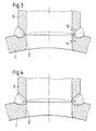
- Fig. 3 einen der Fig.2 entsprechenden Schnitt nach Beendigung des Schweißverfahrens unter Einhaltung des zulässigen Restspaltes und
- Fig. 4 eine der Fig.3 entsprechende Darstellung nach Durchführen einer restspaltfreien Verschweißung.
- 1 shows a section through the end of the pipe branch to be welded on and the associated part of the container wall before the pipe branch is attached,
- 2 shows a sectional view corresponding to FIG. 1 after the pipe branch has been attached to the prepared container wall,
- 3 shows a section corresponding to FIG. 2 after completion of the welding process while observing the permissible residual gap and
- 4 shows a representation corresponding to FIG. 3 after performing a gap-free welding.
Die Figuren 1 und 2 zeigen im Schnitt einen Teil einer gekrümmten Behälterwand 1, bei der es sich beispielsweise um die Wandung eines Sammlers handelt, der mit einer Mehrzahl von radialen Bohrungen 2 versehen ist. Im Bereich jeder dieser Bohrungen 2 wird jeweils ein Rohrabzweig 3 auf die Behälterwand 1 aufgeschweißt. Die Schweißnahtvorbereitung ist am besten in den Figuren 1 und 2 zu erkennen.Figures 1 and 2 show in section a part of a
Diese Darstellungen zeigen, daß der Rohrabzweig 3 am anzuschweißenden Ende ausgehend vom Außendurchmesser mit einer nach innen verlaufenden konischen Verjüngung 4 versehen ist, an deren vorderem Ende sich eine ringförmige Aufstandsfläche 5 ergibt. Diese Aufstandsfläche 5 ist am Ende einer zylindrischen Verlängerung 6 ausgebildet, die unter Bildung eines ringförmigen Einschnittes 7 einstückig am Rohrabzweig 3 ausgebildet ist.These representations show that the
Um den derart vorbereiteten Rohrabzweig 3 an der Behälterwand 1 in Verlängerung einer Bohrung 2 anschweißen zu können, ist die Behälterwand 1 im Bereich jeder Bohrung 2 mit einem Kragen 8 versehen, der durch eine Aussparung 8a in der Behälterwand 1 hergestellt worden ist, und zwar konzentrisch zur Bohrung 2. Innerhalb dieses Kragens 8 ist eine Gegenfläche 9 ausgebildet, die ebenso wie die Aufstandsfläche 5 des Rohrabzweiges 3 rechtwinklig zur Längsachse der Bohrung 2 bzw. des Rohrabzweiges 3 verläuft.In order to be able to weld the
Wie insbesondere Fig. 2 erkennen läßt, ist die Breite der ringförmigen Aufstandsfläche 5 des Rohrabzweiges 3 kleiner als die Breite der an der Behälterwand 1 ausgebildeten Gegenfläche 9. Diese Gegenfläche 9 wird an dem der Bohrung 2 abgewandten Umfang durch einen einstückig aus dem Material der Behälterwand 1 ausgearbeiteten Ring 10 begrenzt, der eine verhältnismäßig geringe Höhe und Dicke aufweist. Die Höhe dieses Ringes 10 ist geringfügig kleiner als die axiale Länge der am Rohrabzweig 3 ausgebildeten Verlängerung 6. Seine Dicke ist derart gering, daß er mit Sicherheit vollständig aufgeschmolzen wird, wenn ein von außen angesetzter Lichtbogen des jeweiligen Schweißverfahrens auf ihn einwirkt. Bei einer bevorzugten Ausführung beträgt die Breite der ringförmigen Aufstandsfläche 5 etwa 1,3 mm, die Breite der Gegenfläche 9 etwa 1,5 mm und die Wanddicke des Ringes 10 maximal 0,5 mm.As can be seen in particular in FIG. 2, the width of the
Wenn der gemäß Fig.1 vorbereitete Rohrabzweig 3 an den entsprechend vorbereiteten Kragen 8 der Behälterwand 1 gemäß Fig.2 angesetzt wird, ergibt sich durch den Ring 10 eine Zentrierung des Rohrabzweiges 3 im Verhältnis zur Bohrung 2. Wenn weiterhin die Breite der ringförmigen Aufstandsfläche 5 des Rohrabzweiges 3 kleiner als der zulässige Restspalt gewählt wird, ergibt sich nach durchgeführtem Schweißvorgang gemäß Fig.3 mit Sicherheit ein Restspalt, der unterhalb des zuläs sigen Wertes liegt, weil der Ring 10 in jedem Fall durch den Lichtbogen aufgeschmolzen wird, so daß der verbleibende Restspalt zwangsläufig unterhalb des zulässigen Wertes liegt. In Fig.3 ist der entstehende Restspalt 11 eingezeichnet. Er liegt wegen der Aufschmelzung des Ringes 10 mit Sicherheit unterhalb des zulässigen Restspaltes 12, der höchstens der Breite der Gegenfläche 9 entspricht.If the
Während die Fig.3 zeigt, daß durch die voranstehend beschriebene Nahtvorbereitung bei einem ausschließlich von außen durchgeführten Lichtbogen-Schweißverfahren durch die Aufschmelzung des Ringes 10 der entstehende Restspalt 11 stets unterhalb des zulässigen Restspaltes 12 liegt, zeigt Fig.4 einen restspaltfrei an die Behälterwand 1 angeschweißten Rohrabzweig 3. Eine derartige Durchschweißung ist beispielsweise mit Hilfe des MAG- oder WIG-Schweißverfahrens durch entsprechende Energieeinbringung möglich, weil der eine geringe Höhe und Dicke aufweisende Ring 10 einem derartigen Durchschweißen keinen nennenswerten Widerstand entgegensetzt. Die Ausgangsverhältnisse vor Beginn des Schweißverfahrens sind in den Figuren 3 und 4 gestrichelt dargestellt.While FIG. 3 shows that the seam preparation described above in an arc welding process carried out exclusively from the outside by the melting of the
- 1 Behälterwand1 container wall
- 2 Bohrung2 holes
- 3 Rohrabzweig3 pipe branch
- 4 Verjüngung4 rejuvenation
- 5 Aufstandsfläche5 footprint
- 6 Verlängerung6 extension
- 7 Einschnitt7 incision
- 8 Kragen8 collar
- 8a Aussparung8a recess
- 9 Gegenfläche9 counter surface
- 10 Ring10 ring
- 11 effektiver Restspalt11 effective residual gap
- 12 zulässiger Restspalt12 permissible residual gap
Claims (2)
dadurch gekennzeichnet,
daß die Breite der ringförmigen Aufstandsfläche (5) des Rohrabzweiges (3) kleiner als der zulässige Restspalt (12) gewählt wird, daß die Breite der an der Behälterwand (1) ausgebildeten Gegenfläche (9) geringfügig größer ausgebildet wird als die Breite der ringförmigen Aufstandsfläche (5) und daß diese Gegenfläche (9) an dem der Bohrung (2) abgewandten Umfang durch einen einstückig aus dem Material der Behälterwand (1) ausgearbeiteten Ring (10) begrenzt wird, dessen Höhe geringfügig kleiner als die axiale Länge der am Rohrabzweig (3) ausgebildeten Verlängerung (6) ist und dessen Dicke derart gering ist, daß der Ring (10) vom von außen angesetzten Lichtbogen des jeweils angewandten Schweißverfahrens mit Sicherheit vollständig aufgeschmolzen wird.1. Method for welding pipe branches (3) by means of an arc welding process carried out exclusively from the outside onto a container wall (1) provided with bores (2), the pipe branch (3) at the end to be welded tapering inwards from the outside diameter and starting from the cylindrical inner diameter is provided with an annular contact surface (5), which is perpendicular to the central axis of the pipe branch (3) at the end of a cylindrical extension (6), the inner diameter of which corresponds to the inner diameter of the pipe branch (3), and with which the pipe branch (3) stands on a corresponding counter surface (9) which is formed on the container wall (1) surrounding the bore (2) as an annular surface, the inside diameter of which corresponds to the diameter of the bore (2),
characterized,
that the width of the annular contact surface (5) of the pipe branch (3) is chosen to be smaller than the permissible residual gap (12), that the width of the counter surface (9) formed on the container wall (1) is made slightly larger than the width of the annular contact surface (5) and that this counter surface (9) is limited on the circumference facing away from the bore (2) by a ring (10) made in one piece from the material of the container wall (1), the height of which is slightly smaller than the axial length of the pipe branch ( 3) trained extension (6) and its thickness is so small that the ring (10) is completely melted by the externally applied arc of the welding process used with certainty.
Applications Claiming Priority (2)
| Application Number | Priority Date | Filing Date | Title |
|---|---|---|---|
| DE3918173 | 1989-06-03 | ||
| DE19893918173 DE3918173C1 (en) | 1989-06-03 | 1989-06-03 |
Publications (1)
| Publication Number | Publication Date |
|---|---|
| EP0401569A1 true EP0401569A1 (en) | 1990-12-12 |
Family
ID=6382023
Family Applications (1)
| Application Number | Title | Priority Date | Filing Date |
|---|---|---|---|
| EP90109314A Withdrawn EP0401569A1 (en) | 1989-06-03 | 1990-05-17 | Process for welding branch pipes onto a container wall provided with bores |
Country Status (3)
| Country | Link |
|---|---|
| EP (1) | EP0401569A1 (en) |
| DE (1) | DE3918173C1 (en) |
| MX (1) | MX172114B (en) |
Cited By (2)
| Publication number | Priority date | Publication date | Assignee | Title |
|---|---|---|---|---|
| WO2003083347A1 (en) * | 2002-03-28 | 2003-10-09 | Hei-Sung Lee | Branch pipe connector for welding pipes |
| CN106514031A (en) * | 2016-12-28 | 2017-03-22 | 中核核电运行管理有限公司 | Connecting structure of branch pipe and main pipe of pipeline of sea water system of nuclear power plant |
Families Citing this family (4)
| Publication number | Priority date | Publication date | Assignee | Title |
|---|---|---|---|---|
| BE1003883A3 (en) * | 1990-10-12 | 1992-07-07 | Gobiet Sa | Process for making casing panels |
| FR2807682A1 (en) * | 2000-04-17 | 2001-10-19 | Soudure Autogene Francaise | Metal-inert-gas and metal-active-gas welding of tubular components involves positioning a flange jutting out from lateral surface of the edge of one component into recess in lateral surface of edge of other component |
| DE10344951B4 (en) * | 2003-09-27 | 2008-02-07 | Zf Friedrichshafen Ag | Joint eye for a piston-cylinder unit |
| CN113263290B (en) * | 2021-07-20 | 2021-10-01 | 烟台锐铭金属材料有限公司 | Welding device and welding method for ship special equipment base |
Citations (4)
| Publication number | Priority date | Publication date | Assignee | Title |
|---|---|---|---|---|
| GB999753A (en) * | 1960-09-02 | 1965-07-28 | Foster Wheeler Ltd | Improvements in or relating to welding |
| GB1007255A (en) * | 1962-07-05 | 1965-10-13 | Foster Wheeler Ltd | Improvements in and relating to welding |
| FR2466646A1 (en) * | 1979-10-03 | 1981-04-10 | Klein Schanzlin & Becker Ag | CENTRIFUGAL PUMP BODY |
| DE3715521C1 (en) * | 1987-05-09 | 1988-08-25 | Balcke-Duerr Ag, 4030 Ratingen, De | Metal-active gas welding method for pipe branches - using ceramic support ring around inside wall of hole in container to which pipe branch is to be welded |
Family Cites Families (2)
| Publication number | Priority date | Publication date | Assignee | Title |
|---|---|---|---|---|
| US1857526A (en) * | 1929-12-16 | 1932-05-10 | Smith Corp A O | Method of electric welding pressure vessels |
| US3195229A (en) * | 1962-05-21 | 1965-07-20 | Foster Wheeler Corp | Method of butt welding metal tubes |
-
1989
- 1989-06-03 DE DE19893918173 patent/DE3918173C1/de not_active Expired - Lifetime
-
1990
- 1990-05-17 EP EP90109314A patent/EP0401569A1/en not_active Withdrawn
- 1990-05-28 MX MX2090790A patent/MX172114B/en unknown
Patent Citations (4)
| Publication number | Priority date | Publication date | Assignee | Title |
|---|---|---|---|---|
| GB999753A (en) * | 1960-09-02 | 1965-07-28 | Foster Wheeler Ltd | Improvements in or relating to welding |
| GB1007255A (en) * | 1962-07-05 | 1965-10-13 | Foster Wheeler Ltd | Improvements in and relating to welding |
| FR2466646A1 (en) * | 1979-10-03 | 1981-04-10 | Klein Schanzlin & Becker Ag | CENTRIFUGAL PUMP BODY |
| DE3715521C1 (en) * | 1987-05-09 | 1988-08-25 | Balcke-Duerr Ag, 4030 Ratingen, De | Metal-active gas welding method for pipe branches - using ceramic support ring around inside wall of hole in container to which pipe branch is to be welded |
Cited By (2)
| Publication number | Priority date | Publication date | Assignee | Title |
|---|---|---|---|---|
| WO2003083347A1 (en) * | 2002-03-28 | 2003-10-09 | Hei-Sung Lee | Branch pipe connector for welding pipes |
| CN106514031A (en) * | 2016-12-28 | 2017-03-22 | 中核核电运行管理有限公司 | Connecting structure of branch pipe and main pipe of pipeline of sea water system of nuclear power plant |
Also Published As
| Publication number | Publication date |
|---|---|
| DE3918173C1 (en) | 1990-06-07 |
| MX172114B (en) | 1993-12-03 |
Similar Documents
| Publication | Publication Date | Title |
|---|---|---|
| DE2236758A1 (en) | WELDING PROCESS AND DEVICE FOR ITS IMPLEMENTATION | |
| EP2020272A1 (en) | Method and device for welding circular seams | |
| EP0401569A1 (en) | Process for welding branch pipes onto a container wall provided with bores | |
| DE1627483A1 (en) | Process for joining clad pipes by welding without deposit metal | |
| DE2713309A1 (en) | PROCESS FOR ELIMINATING RESIDUAL MAGNETISM DURING LONGITUDINAL SEAM WELDING ON A PIPE | |
| EP0587926B1 (en) | Fuel rod for nuclear reactor and welding device for its manufacture | |
| DE19715327B4 (en) | A method of forming a bead on a sleeve pipe end | |
| DE3715521C1 (en) | Metal-active gas welding method for pipe branches - using ceramic support ring around inside wall of hole in container to which pipe branch is to be welded | |
| EP1506834A1 (en) | Method, welding device and welding filler for welding a seam between two workpieces, in particular for manufacturing a level measuring device | |
| DE3822807C1 (en) | Method of welding thin-walled heat-exchanger tubes to the rear of a tube plate | |
| DE2612661C2 (en) | Branch for welding pipes to a collector | |
| CH362890A (en) | Fastening a metallic corrugated pipe in a metallic connector and method for producing the fastening | |
| DE2054337B2 (en) | BRACKET FOR A CONTROL ROD GUIDE TUBE | |
| DE4429379C2 (en) | Vacuum interrupter with steam shield held in isolation | |
| EP0040673A1 (en) | Apparatus for electric arc welding | |
| DE3121296A1 (en) | VALVE TURBLE AND METHOD FOR THE PRODUCTION THEREOF | |
| DE2034133A1 (en) | Connection piece as well as method and device for its attachment | |
| EP0461340B1 (en) | Nozzle for sliding gate valve | |
| DE4031868C1 (en) | Welding annular component onto support by industrial robot - moving welding head in welding plane about partial circuit matching number of burners | |
| DE650785C (en) | Butt weld connection for pipes laid at an angle with spherical shell-shaped widened, pushed onto a spherical insert ring on its outer surface and welded to this and under itself ends | |
| DE2251147A1 (en) | CONICAL PIPE SOCKET CARRYING A FLANGE RING | |
| DE2723678A1 (en) | ELECTRODES FOR SHIELD WELDING WITH TUNGSTEN ELECTRODE | |
| EP3730826A1 (en) | Method for producing a pipe with connecting flange | |
| DE833752C (en) | Auxiliary ring with ventilation for the electrical welding of pins | |
| DE7609197U1 (en) | BRANCH FOR WELDING PIPES TO A COLLECTOR |
Legal Events
| Date | Code | Title | Description |
|---|---|---|---|
| PUAI | Public reference made under article 153(3) epc to a published international application that has entered the european phase |
Free format text: ORIGINAL CODE: 0009012 |
|
| AK | Designated contracting states |
Kind code of ref document: A1 Designated state(s): DE ES IT NL |
|
| STAA | Information on the status of an ep patent application or granted ep patent |
Free format text: STATUS: THE APPLICATION IS DEEMED TO BE WITHDRAWN |
|
| 18D | Application deemed to be withdrawn |
Effective date: 19910613 |