US1857526A - Method of electric welding pressure vessels - Google Patents
Method of electric welding pressure vessels Download PDFInfo
- Publication number
- US1857526A US1857526A US414387A US41438729A US1857526A US 1857526 A US1857526 A US 1857526A US 414387 A US414387 A US 414387A US 41438729 A US41438729 A US 41438729A US 1857526 A US1857526 A US 1857526A
- Authority
- US
- United States
- Prior art keywords
- welding
- connector
- wall
- vessel
- shoulder
- Prior art date
- Legal status (The legal status is an assumption and is not a legal conclusion. Google has not performed a legal analysis and makes no representation as to the accuracy of the status listed.)
- Expired - Lifetime
Links
- 238000003466 welding Methods 0.000 title description 31
- 238000000034 method Methods 0.000 title description 9
- 239000002184 metal Substances 0.000 description 8
- 238000010891 electric arc Methods 0.000 description 3
- 238000000151 deposition Methods 0.000 description 2
- 238000012986 modification Methods 0.000 description 1
- 230000004048 modification Effects 0.000 description 1
- 238000007493 shaping process Methods 0.000 description 1
Images
Classifications
-
- B—PERFORMING OPERATIONS; TRANSPORTING
- B23—MACHINE TOOLS; METAL-WORKING NOT OTHERWISE PROVIDED FOR
- B23K—SOLDERING OR UNSOLDERING; WELDING; CLADDING OR PLATING BY SOLDERING OR WELDING; CUTTING BY APPLYING HEAT LOCALLY, e.g. FLAME CUTTING; WORKING BY LASER BEAM
- B23K33/00—Specially-profiled edge portions of workpieces for making soldering or welding connections; Filling the seams formed thereby
- B23K33/004—Filling of continuous seams
-
- F—MECHANICAL ENGINEERING; LIGHTING; HEATING; WEAPONS; BLASTING
- F16—ENGINEERING ELEMENTS AND UNITS; GENERAL MEASURES FOR PRODUCING AND MAINTAINING EFFECTIVE FUNCTIONING OF MACHINES OR INSTALLATIONS; THERMAL INSULATION IN GENERAL
- F16L—PIPES; JOINTS OR FITTINGS FOR PIPES; SUPPORTS FOR PIPES, CABLES OR PROTECTIVE TUBING; MEANS FOR THERMAL INSULATION IN GENERAL
- F16L41/00—Branching pipes; Joining pipes to walls
- F16L41/08—Joining pipes to walls or pipes, the joined pipe axis being perpendicular to the plane of a wall or to the axis of another pipe
- F16L41/082—Non-disconnectable joints, e.g. soldered, adhesive or caulked joints
- F16L41/084—Soldered joints
-
- Y—GENERAL TAGGING OF NEW TECHNOLOGICAL DEVELOPMENTS; GENERAL TAGGING OF CROSS-SECTIONAL TECHNOLOGIES SPANNING OVER SEVERAL SECTIONS OF THE IPC; TECHNICAL SUBJECTS COVERED BY FORMER USPC CROSS-REFERENCE ART COLLECTIONS [XRACs] AND DIGESTS
- Y10—TECHNICAL SUBJECTS COVERED BY FORMER USPC
- Y10S—TECHNICAL SUBJECTS COVERED BY FORMER USPC CROSS-REFERENCE ART COLLECTIONS [XRACs] AND DIGESTS
- Y10S220/00—Receptacles
- Y10S220/04—Bushings
-
- Y—GENERAL TAGGING OF NEW TECHNOLOGICAL DEVELOPMENTS; GENERAL TAGGING OF CROSS-SECTIONAL TECHNOLOGIES SPANNING OVER SEVERAL SECTIONS OF THE IPC; TECHNICAL SUBJECTS COVERED BY FORMER USPC CROSS-REFERENCE ART COLLECTIONS [XRACs] AND DIGESTS
- Y10—TECHNICAL SUBJECTS COVERED BY FORMER USPC
- Y10S—TECHNICAL SUBJECTS COVERED BY FORMER USPC CROSS-REFERENCE ART COLLECTIONS [XRACs] AND DIGESTS
- Y10S220/00—Receptacles
- Y10S220/29—Welded seam
Definitions
- FIG. 5 is a diagrammatic representation of FIG. 5.
- This invention relates to a method of electric welding pressure vessels.
- the invention is particularly applicable to the welding of tubular connections to thick a walled pressure vessels.
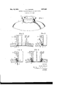
- Figure 1 is a perspective view of a manway welded to a pressure vessel.
- Fig. 2 is a longitudinal section through a manway and the adjacent portion of the vessel showing the parts prepared for weld-
- Fig. 3 is a similar view showing a manway and the adjacent portion of the vessel'during the first step of the welding operation.
- Fig. 4. is a longitudinal section through a manway and the adjacent portion of the vess'el showing a later Welding step.
- Fig. 5 is a similar view showing the completed weld.
- the thick wall 1 of the pressure vessel is provided withan opening 2, which is greater in diameter than the inside diameter of the manway 3 to-be welded in the opening.
- the thick wall 1 around the opening 2 is chamtered, forming an annular lip 4.
- the lip 4 is chamfered to form a small annular projection 5 and a shoulder 6.
- the wall '7 of the manway 3 has its end chamfered to' reduce its outside diameter sufficiently to cause the manway to rest upon the annular projection 5 when it is inserted into the opening 2.
- the shoulder 6 prevents lateral movement of the manway 3 after it is inserted into the opening 2 and positioned for weldin
- An annular welding groove 8 is formed by the lip 4, which serves as the bottom, and the wall 7 of the manway 3 and the wall 1 of the pressure vessel, which serve as sides of the groove.
- One terminal of a source of welding current is attached to the work and the other to a fusible metallic weldrod 9.
- the welding circuit is closed, and the metallic weldrod9 is touched against the lip 4 at the bottom of the welding groove 8 and quickly withdrawn, striking an are between the weldrod and the bottom of the groove.
- the intense heat causes the weldrod 9 to fuse away and to fill the welding groove 8 with molten welding metal 10.
- the lip 4 and the projection 5 are burned away, preferably by an electric arc, to form an annular welding groove 11 inside the vessel between the wall 1 of the vessel and the wall 7 of the manway 3, as shown in Fig. 4:.
- This invention provides a, rapid and accurate method for centering the tubular connection in the opening in the wall of the pressure vessel.
- the process'of welding a tubular connector to a thick walled vessel having an opening comprising chamfering the wall defining the opening to provide a welding groove and a shoulder for receiving and centering the connector, chamfering the wall of the connector to reduce the thickness of the lower edge and prepare it for seating on the shoulder, mounting the connector on the shoulder to center it and complete a welding groove, depositing metal in the welding roove by means of an electric arc, and weldmg from the lower side to fuse the shoulder and lower edge of the connector and deposit additional weld-metal to unite the connector and vessel wall.
Landscapes
- Engineering & Computer Science (AREA)
- Mechanical Engineering (AREA)
- General Engineering & Computer Science (AREA)
- Butt Welding And Welding Of Specific Article (AREA)
Description
May. 10, 1932. H. .1. BURNlSH METHOD OF ELECTRIC WELDING PRESSURE VESSELS Filed Dec. 16. 1929 FIG- 3.
FIG. 2.
FIG. 5.
FIG. 4--
IN VEN TOR.
Howard JBurm'sh A TTORNEY.
' Patented May 10, 19152 UNITED STATES PATENT OFFICE HOWARD J. BURNISH, OF MILWAUKEE, WISCONSIN, ASSIGNOR A. 0. SMITH CORPORA- TION, OF MILWAUKEE, WISCONSIN, A CORPORATION OF NEW YORK METHOD 015 ELECTRIC WELDING PRESSURE VESSELS Application filed December 16, 1929. Serial No. 414,387.
This invention relates to a method of electric welding pressure vessels.
The invention is particularly applicable to the welding of tubular connections to thick a walled pressure vessels.
. to more accurately center the tubular connection with respect to an opening in the plate or vessel wall.
An embodiment of the invention is illustrated in 'the accompanying drawings in which the views are as follows:
Figure 1 is a perspective view of a manway welded to a pressure vessel.
Fig. 2 is a longitudinal section through a manway and the adjacent portion of the vessel showing the parts prepared for weld- Fig. 3 is a similar view showing a manway and the adjacent portion of the vessel'during the first step of the welding operation. Fig. 4. is a longitudinal section through a manway and the adjacent portion of the vess'el showing a later Welding step.
Fig. 5 is a similar view showing the completed weld.
The thick wall 1 of the pressure vessel is provided withan opening 2, which is greater in diameter than the inside diameter of the manway 3 to-be welded in the opening. The thick wall 1 around the opening 2 is chamtered, forming an annular lip 4. The lip 4: is chamfered to form a small annular projection 5 and a shoulder 6.
The wall '7 of the manway 3 has its end chamfered to' reduce its outside diameter sufficiently to cause the manway to rest upon the annular projection 5 when it is inserted into the opening 2. The shoulder 6 prevents lateral movement of the manway 3 after it is inserted into the opening 2 and positioned for weldin An annular welding groove 8 is formed by the lip 4, which serves as the bottom, and the wall 7 of the manway 3 and the wall 1 of the pressure vessel, which serve as sides of the groove.
One terminal of a source of welding current is attached to the work and the other to a fusible metallic weldrod 9. The welding circuit is closed, and the metallic weldrod9 is touched against the lip 4 at the bottom of the welding groove 8 and quickly withdrawn, striking an are between the weldrod and the bottom of the groove. The intense heat causes the weldrod 9 to fuse away and to fill the welding groove 8 with molten welding metal 10.
When the groove 8 is substantially filled, the lip 4 and the projection 5 are burned away, preferably by an electric arc, to form an annular welding groove 11 inside the vessel between the wall 1 of the vessel and the wall 7 of the manway 3, as shown in Fig. 4:.
An arc is then struck between a metallic weldrod 12 and the bottom of the welding groove 11 and the groove 11 is filled with molten welding metal 13 to complete the weld.
This invention provides a, rapid and accurate method for centering the tubular connection in the opening in the wall of the pressure vessel.
be used within Various modifications may the scope of this invention.
I claim:
1. The process of welding a tubular connector to a thick walled vessel having an opening, comprising chamfering the wall defining the opening to provide a welding groove and a shoulder for receiving and centering the connector, shaping the wall of the connector to seat on the shoulder, mounting the connector on the shoulder to center it and complete the welding groove, and welding from both sides of the vessel wall to fuse the shoulder and lower edge of the connector together and deposit weld metal uniting the connector and vessel wall.
2. The process of welding a tubular connector to a thick walled vessel having an opening, comprising chamfering the wall .defining the opening to provide a dish shaped depression in the upper surface of the vessel around the opening and a shoulder for receiving and centering the connector, mounting the connector on the shoulder to center it and 100 complete the welding groove, depositing metal in *the welding groove by means of an electric arc, and welding from the lower side to use theshoulder and lower edge of the connector together and deposit additional we'llrll metal to unite the connector and vessel wa 3. The process'of welding a tubular connector to a thick walled vessel having an opening, comprising chamfering the wall defining the opening to provide a welding groove and a shoulder for receiving and centering the connector, chamfering the wall of the connector to reduce the thickness of the lower edge and prepare it for seating on the shoulder, mounting the connector on the shoulder to center it and complete a welding groove, depositing metal in the welding roove by means of an electric arc, and weldmg from the lower side to fuse the shoulder and lower edge of the connector and deposit additional weld-metal to unite the connector and vessel wall.
4. The process of welding a tubular connector to a thick walled vessel having an opening, comprising chamfering the wall defining the opening to provide a' welding groove and a shoulder for receiving and centering the connector, chamfering the Wall of the connector-to reduce the thickness of the lower edge and prepare it for seating inside the shoulder, mounting the connector with its lower end edge inside the shoulder to center it and complete the weld groove, and welding from both sides of the vessel wall to fuse the shoulder and lower edge of the connector together and deposit weld metal to unite the connector and vessel wall.
In witness whereof, I have hereunto signed 40 my name at Milwaukee, Wisconsin, this 13th day of December 1929. Ho-W RD J. BURNISH.
Priority Applications (1)
| Application Number | Priority Date | Filing Date | Title |
|---|---|---|---|
| US414387A US1857526A (en) | 1929-12-16 | 1929-12-16 | Method of electric welding pressure vessels |
Applications Claiming Priority (1)
| Application Number | Priority Date | Filing Date | Title |
|---|---|---|---|
| US414387A US1857526A (en) | 1929-12-16 | 1929-12-16 | Method of electric welding pressure vessels |
Publications (1)
| Publication Number | Publication Date |
|---|---|
| US1857526A true US1857526A (en) | 1932-05-10 |
Family
ID=23641236
Family Applications (1)
| Application Number | Title | Priority Date | Filing Date |
|---|---|---|---|
| US414387A Expired - Lifetime US1857526A (en) | 1929-12-16 | 1929-12-16 | Method of electric welding pressure vessels |
Country Status (1)
| Country | Link |
|---|---|
| US (1) | US1857526A (en) |
Cited By (8)
| Publication number | Priority date | Publication date | Assignee | Title |
|---|---|---|---|---|
| US2620529A (en) * | 1949-07-01 | 1952-12-09 | Brown Ind Inc | Pattern and pattern making |
| DE1190596B (en) * | 1960-08-04 | 1965-04-08 | United Kingdom Atomic En Autho | Process for TIG welding of end caps on nuclear reactor fuel element casings |
| US3440391A (en) * | 1966-07-11 | 1969-04-22 | Foster Wheeler Corp | Internal tube welding |
| WO1986004973A1 (en) * | 1985-02-22 | 1986-08-28 | Promat Engineering Services Limited | Transition pieces |
| DE3918173C1 (en) * | 1989-06-03 | 1990-06-07 | Balcke-Duerr Ag, 4030 Ratingen, De | |
| US5104155A (en) * | 1985-02-22 | 1992-04-14 | Promat Engineering Services Limited | Transition pieces |
| US20130106123A1 (en) * | 2011-10-27 | 2013-05-02 | GM Global Technology Operations LLC | Structural integrity welded assembly |
| US9989182B2 (en) * | 2014-06-30 | 2018-06-05 | Sunspin Pty Ltd. | Method of forming a sealed joint between a tubular article and a sheet article |
-
1929
- 1929-12-16 US US414387A patent/US1857526A/en not_active Expired - Lifetime
Cited By (9)
| Publication number | Priority date | Publication date | Assignee | Title |
|---|---|---|---|---|
| US2620529A (en) * | 1949-07-01 | 1952-12-09 | Brown Ind Inc | Pattern and pattern making |
| DE1190596B (en) * | 1960-08-04 | 1965-04-08 | United Kingdom Atomic En Autho | Process for TIG welding of end caps on nuclear reactor fuel element casings |
| US3440391A (en) * | 1966-07-11 | 1969-04-22 | Foster Wheeler Corp | Internal tube welding |
| WO1986004973A1 (en) * | 1985-02-22 | 1986-08-28 | Promat Engineering Services Limited | Transition pieces |
| US5104155A (en) * | 1985-02-22 | 1992-04-14 | Promat Engineering Services Limited | Transition pieces |
| DE3918173C1 (en) * | 1989-06-03 | 1990-06-07 | Balcke-Duerr Ag, 4030 Ratingen, De | |
| US20130106123A1 (en) * | 2011-10-27 | 2013-05-02 | GM Global Technology Operations LLC | Structural integrity welded assembly |
| US8561877B2 (en) * | 2011-10-27 | 2013-10-22 | GM Global Technology Operations LLC | Structural integrity welded assembly |
| US9989182B2 (en) * | 2014-06-30 | 2018-06-05 | Sunspin Pty Ltd. | Method of forming a sealed joint between a tubular article and a sheet article |
Similar Documents
| Publication | Publication Date | Title |
|---|---|---|
| US1857526A (en) | Method of electric welding pressure vessels | |
| US1903315A (en) | Pipe joint | |
| US20090224530A1 (en) | Welded butt joints on tubes having dissimilar end preparations | |
| US3769489A (en) | Welding of tubes to tube plates | |
| US2228087A (en) | Vapor-electric device and method of making the same | |
| US2372712A (en) | Butt-welded joint between lined parts | |
| US4163869A (en) | Electrical connection between aluminum conductors | |
| US1810902A (en) | Electric arc welding of pipe joints | |
| KR880001289B1 (en) | Method of manufacture of a hoop for the vessel of a nuclear reactor | |
| US1606894A (en) | Electric welding | |
| US2268343A (en) | Welding method | |
| US1787580A (en) | Method of electrically welding tubular connections for thick-walled vessels | |
| US2194272A (en) | Welding | |
| US1934064A (en) | Lining of high pressure tubular articles | |
| US1978610A (en) | Lined pressure vessel nozzle | |
| US1278357A (en) | Shell and projectile. | |
| US1748577A (en) | Method of forming tank ends | |
| US2928932A (en) | Sheet metal weld assembly | |
| US2691214A (en) | Method of making crucibles for heating thermoplastic materials | |
| US3149818A (en) | Elastic wedge-shaped gate member for slide stop valves and method of producing same | |
| US1748576A (en) | Tank and method of making the same | |
| US2829234A (en) | Slagforming body for use in butt-welding | |
| US2160039A (en) | Method of making bicycle forks | |
| US1759427A (en) | Electrically-welded pipe and method of manufacturing the same | |
| US2083234A (en) | Method of welding |