EP0401237B1 - A heat installation for premises with water as a heat transmitting medium - Google Patents
A heat installation for premises with water as a heat transmitting medium Download PDFInfo
- Publication number
- EP0401237B1 EP0401237B1 EP89902180A EP89902180A EP0401237B1 EP 0401237 B1 EP0401237 B1 EP 0401237B1 EP 89902180 A EP89902180 A EP 89902180A EP 89902180 A EP89902180 A EP 89902180A EP 0401237 B1 EP0401237 B1 EP 0401237B1
- Authority
- EP
- European Patent Office
- Prior art keywords
- pipes
- pipe
- elements
- shell
- designed
- Prior art date
- Legal status (The legal status is an assumption and is not a legal conclusion. Google has not performed a legal analysis and makes no representation as to the accuracy of the status listed.)
- Expired - Lifetime
Links
- 238000009434 installation Methods 0.000 title claims abstract description 40
- XLYOFNOQVPJJNP-UHFFFAOYSA-N water Substances O XLYOFNOQVPJJNP-UHFFFAOYSA-N 0.000 title claims abstract description 13
- 230000007704 transition Effects 0.000 claims abstract description 11
- 210000002445 nipple Anatomy 0.000 claims description 8
- 239000000463 material Substances 0.000 claims description 7
- 239000011810 insulating material Substances 0.000 claims description 3
- 238000007789 sealing Methods 0.000 claims description 3
- 238000004891 communication Methods 0.000 claims description 2
- 238000010276 construction Methods 0.000 claims description 2
- 230000005611 electricity Effects 0.000 claims 1
- 238000013461 design Methods 0.000 description 13
- 239000007769 metal material Substances 0.000 description 3
- 238000000034 method Methods 0.000 description 3
- 230000008859 change Effects 0.000 description 2
- 238000009408 flooring Methods 0.000 description 2
- 238000009413 insulation Methods 0.000 description 2
- 239000007787 solid Substances 0.000 description 2
- 239000008399 tap water Substances 0.000 description 2
- 235000020679 tap water Nutrition 0.000 description 2
- 230000006978 adaptation Effects 0.000 description 1
- 230000004075 alteration Effects 0.000 description 1
- XAGFODPZIPBFFR-UHFFFAOYSA-N aluminium Chemical compound [Al] XAGFODPZIPBFFR-UHFFFAOYSA-N 0.000 description 1
- 229910052782 aluminium Inorganic materials 0.000 description 1
- 230000005540 biological transmission Effects 0.000 description 1
- 238000005266 casting Methods 0.000 description 1
- 238000005520 cutting process Methods 0.000 description 1
- 238000011161 development Methods 0.000 description 1
- 238000010438 heat treatment Methods 0.000 description 1
- 238000003780 insertion Methods 0.000 description 1
- 230000037431 insertion Effects 0.000 description 1
- JEIPFZHSYJVQDO-UHFFFAOYSA-N iron(III) oxide Inorganic materials O=[Fe]O[Fe]=O JEIPFZHSYJVQDO-UHFFFAOYSA-N 0.000 description 1
- 238000011031 large-scale manufacturing process Methods 0.000 description 1
- 238000003754 machining Methods 0.000 description 1
- 238000004519 manufacturing process Methods 0.000 description 1
- 238000000465 moulding Methods 0.000 description 1
- 230000000630 rising effect Effects 0.000 description 1
- 230000009528 severe injury Effects 0.000 description 1
- 239000002023 wood Substances 0.000 description 1
Images


Classifications
-
- F—MECHANICAL ENGINEERING; LIGHTING; HEATING; WEAPONS; BLASTING
- F24—HEATING; RANGES; VENTILATING
- F24D—DOMESTIC- OR SPACE-HEATING SYSTEMS, e.g. CENTRAL HEATING SYSTEMS; DOMESTIC HOT-WATER SUPPLY SYSTEMS; ELEMENTS OR COMPONENTS THEREFOR
- F24D19/00—Details
- F24D19/0002—Means for connecting central heating radiators to circulation pipes
- F24D19/0009—In a two pipe system
-
- F—MECHANICAL ENGINEERING; LIGHTING; HEATING; WEAPONS; BLASTING
- F24—HEATING; RANGES; VENTILATING
- F24D—DOMESTIC- OR SPACE-HEATING SYSTEMS, e.g. CENTRAL HEATING SYSTEMS; DOMESTIC HOT-WATER SUPPLY SYSTEMS; ELEMENTS OR COMPONENTS THEREFOR
- F24D3/00—Hot-water central heating systems
- F24D3/10—Feed-line arrangements, e.g. providing for heat-accumulator tanks, expansion tanks ; Hydraulic components of a central heating system
- F24D3/1058—Feed-line arrangements, e.g. providing for heat-accumulator tanks, expansion tanks ; Hydraulic components of a central heating system disposition of pipes and pipe connections
- F24D3/1066—Distributors for heating liquids
- F24D3/1075—Built up from modules
Definitions
- the present invention relates to a heat installation for buildings using water as a heat transmitting medium, and is set forth in greater detail in the preamble of patent claim 1.
- Such conventional heat installations comprise loosely layed visible piping or piping accommodated in walls and floors respectively. Said installations are designed throughout either as one- or as two-pipe-systems. In all of the cases the installation has been performed by artisans with a manual individual pipe laying and assembly operation, which is very expensive and time-consuming. In case such a system is to be installed in already finished houses, usually it is required that the floors and walls be torn open for an invisible pipe laying, or if the pipe laying is to be visible, said pipes will constitute a strongly disturbing factor and also usually will emit heat in places where heat is not required, which to some extent is true as regards pipe laying in walls and floors, in which the heat insulation is unsatisfactory.
- Invisible pipe laying may involve risk of leakage, which is hard to discover, with severe damages as a result, when leakage has been discovered after usually an extended period of time, and the development of mould, rot and rust.
- Irrespective of whether an installation is done in connection with the erection of a building or in an already finished building painters, carpenters, floor-layers etc. have so far been required to be able to complete their work or else they were required to perform additional work, when the installation contractors have completed their work.
- the problem whether to select an one-pipe- or a two-pipe-system has also often been difficult to solve.
- One of the two systems may have been suitable for e.g. one specific module or building element, while the other one had been suitable for other modules.
- the object of the present invention is to suggest an improved heat installation, in which water is used as a heat transmission medium and which avoids the drawbacks mentioned above and promotes the state of the art in this field in various respects.
- Fig. 1 of the accompanying drawings to lay one branch along one portion of a building, while another branch provides another portion of the building with heat.
- said one branch can be designed as an one-pipe-system and the other branch as a two-pipe-system, and in this way different heating requirements can be met in an optimal manner.
- the production of the various components, which the system includes, can be done in simple, fast and inexpensive ways due to a large scale production, e.g. through casting or injecting molding of metallic and plastic materials respectively, starting with uniform modules for radiator connection elements, which subsequently can be easily and specifically adapted for e.g. one- or two-pipe-operation and having varying choking/heat emission capacities respectively.
- radiators having an arbitrary size/heat emission capacity in arbitrarily selected areas and, if that is required, at the same time select an adequate circulation of the heat medium through the radiator.
- This installation can easily be designed to smoothly and in principle without problems be passed by a door opening in a way that is set forth in the following description and the accompanying drawings, such an installation section preferably being designed as a threshold. It is then possible, in case this is required in a particular case, to without problems obtain a reversal of the pipes, i.e. to let the forward and return pipes change places, the upper pipe on one side of the door opening becoming the bottom pipe on the other side. All the components in the installation can be designed to emit heat in an adequate manner, i.e.
- a main connection element 1 is shown, which in a way known per se is designed to be connected to main pipings (not shown) to and from e.g. a central heater (not shown) and which is shown in more detail in Fig. 2.
- connection elements 2 are shown in more detail and in Fig. 4 inner corner elements 3 and outer corner elements 4 respectively are shown.
- Threshold transition elements 5 and 7 are mirror-symmetrically alike.
- Element 5 is shown in detail in Fig. 5.
- a threshold 6 is disposed between such threshold transition elements.
- a radiator connection element 8 is shown in detail in Fig. 6. Terminal parts 9 for blind loop ends are shown and in Fig. 7 a joint element 10 is shown in detail, while in Fig. 1 radiators 11 are shown, which can be conventional hot water radiators having conventional radiator valves 12.
- the heat installation shown in Fig. 1 is provided with two blind branches, it being easy to design each branch, thanks to the characterizing features of the present invention, according to individual needs at any time for an one-pipe-operation or a two-pipe-operation. It is easy to design e.g. one of the branches for one-pipe-operation and the other for two-pipe-operation, there being no need to make any exterior alterations. It is also possible, at any time, to add to the branches, i.e. extend them and/or mutually connect their ends. Also, it is easy to later on connect additional radiators and to remove existing radiators respectively from the system.
- a heat installation according to the invention advantageously can be designed as a basic module system or building element system, selling the various components advantageously being done in self-service outlets and an installation subsequently being done by the buyer himself, e.g. a home or an apartment owner. It is true that the majority of the components can be delivered in one single standard design as to dimensions, but it is easy to provide connection elements 2 and thresholds 6 in various lengths, it thereby being easy and simple to accommodate them to different installation dimensions and designs, particularly because the exact location of the various components per se easily can be adjusted within certain limits thanks to the insertion principle and the relative displaceability together with maintained functions for the rest which result from it.
- Main connection element 1 shown in Fig. 2 comprises an arbitrarily designed strip- or block-shaped shell 13, which can be solid or hollow and be made of a plastic and/or metallic material having a front or room side 14 and a rear or connection side 15, from which connection pieces 16,17 project, which are placed on different levels and which are connected at right angles to one return pipe and one forward pipe respectively, namely pipe 18 and pipe 19 respectively, which extend through the main connection element in its longitudinal direction.
- Pipes 18,19 are usually open in both directions, but in case just one branch is to issue from said main connection element, one of the end openings of pipes 18,19 can be closed, e.g. plugged up.
- Front side 14 and upper side 20 of the main connection element can be decoratively designed in an arbitrary way, suitably in the same way and with the same profile dimensions as the following components, which are included in the installation.
- Pipe 18 is of course the feed pipe for hot water and pipe 19 the return pipe for colder water.
- the upper pipe is e.g. the feed pipe.
- Pieces 16,17 advantageously can comprise essentially tubular through elements (see Fig. 2a), which extend through transverse cuts in shell 13 and engage with closed ends having flanges 21 in a somewhat broader recess 22 on the room-side of the shell, nipples 23 and 24 respectively being secured on ends, which project from the rear side of said pieces and e.g.
- Connection element 2 shown in Fig. 3, comprises a shell 25 comprising e.g. a closed external housing 26, which accommodates ducts 27,28, one disposed above the other, which are designed to function as a return pipe and a forward pipe respectively and which project beyond the two ends of the shell in its longitudinal direction, e.g. different distances at the two sides, as shown in Fig. 3 b, at least as regards elements adjacent a joint element to be described subsequently.
- Ducts 27,28 can be integral with shell 25 by means of bridge portions 29 according to Fig. 3a.
- said shell can be provided with central transverse control elements 30 designed as holes and/or casings for screws or the like, by means of which said elements can be fastened to e.g. a wall 81.
- connection element can be made all of a piece, of a plastic and/or metallic material, e.g. aluminum, and remaining cavities can advantageously be filled with an insulating material 31 in a way known per se as regards the method.
- ducts 27,28 according to Fig. 3a can be designed solely as control elements, which possibly are not through elements in their longitudinal direction and/or their circumferential direction, for separately introduced ducts, which possibly subsequently can be fastened to the shells, if that is desirable.
- connection elements are provided with circumferential external bevellings 82.
- FIGs. 4a and 4c an inner corner element 32 is shown, legs 33,34 of which suitably having the same external profile as said connection elements and said main connection element.
- An outer corner element 35 according to Figs. 4b and 4d is designed in a similar fashion having legs 36 and 37 and the only difference between the two elements is that the room side, i.e. the possibly decorated side, in one of the cases is an inner corner and in the other case an outer corner.
- pipes 18,19 are disposed one above the other and their ends are provided with circumferential grooves 38, in which O-rings or the like 39 are introduced.
- corner elements are connected in a simple way to adjacent connection elements, the projecting duct ends of the latter being inserted in legs at least such a distance, that O-rings or the like 39 are passed and in this way are expanded and consequently seal.
- Said corner elements can also be made in one piece of a plastic and/or a metallic material. They can be made hollow according to Fig. 3a or possibly solid.
- Threshold transition element 5 shown in Fig. 5, corresponds mirror-symmetrically to threshold transition element 7, and thus the latter will not be shown or described in more detail. It is shown that element 5 has an upended portion 40, similar to the components described above and which changes into a horizontal portion 41. The latter portion suitably is, as regards the external profile, similar to threshold 6, and in this way an adaptation to various threshold profiles can easily be done. It is shown in the various views in Fig. 5 that upper pipe 19 changes via an obliquely downwardly directed passage 42 into a lower extension of the same pipe, while lower pipe 18 via a passage 43, in an obliquely lateral direction, changes into a laterally shifted extension of the same pipe. Fig.
- 5e shows that the two pipes 18,19 are disposed within the horizontal threshold transition portion 41 adjacent each other in the same horizontal plane.
- the same pipe orientation is used within threshold 6, not shown in detail, which then is connected to the mirror-symmetrically designed threshold transition element 7, in which pipe 19 again being disposed on top within portion 40 or possibly, if it is desirable in a special case, at the bottom, which is easily done e.g. if passage 42 does not extend in a vertical plane obliquely downwardly but obliquely downwardly in a lateral direction in either element 5 or 7, while lower pipe 18 continues straight ahead, in which way a reversal can be attained, which however normally probably is not required.
- the end openings of pipes 18,19 are, in the same way as is shown in Fig. 4, provided with internal grooves 44 and O-rings or the like 45 introduced in said grooves. Also, in required places possibly screwed plugs 46,47 can be used in order to render possible a chip removal machining operation or the like.
- Radiator connection element 8 shown in Fig. 6, is mainly similar in its design to the above-described elements and comprises a shell 48, which accommodates pipes 18,19, the end areas of which, in a way which corresponds to the above-described elements, are provided with internal grooves 49 and O-rings or the like 50 introduced in said grooves.
- connection elements 2 can be sealingly connected in the two directions, and a longitudinal adjustment can thus be obtained.
- two similar vertical cylindrical cuts 51 are disposed in shell 48, at a distance in a horizontal direction from each other and e.g. having a step-shaped expansion element 52 at their lower ends and a similar constriction element 53 at their upper ends, from which said cut with its smallest diameter extends outwardly through the upper side of shell 48.
- each cut 51 an insert 54 or 55 is introduced.
- Said inserts have a common principal design, namely a cylindrical body, which essentially fills the respective cuts and has a lower flange 56 and 57 respectively and an upper step-shaped end 58 and 59 respectively as well as connection pieces 60 and 61 respectively, which project through the upper cut opening.
- On said pieces preferably provided with external threads, suitably nipples 62 can be screwed, which allow, via seals or the like 63, a sealing against said shell and said insert as well as a sealed engagement of said flanges 56,57 against the adjacent portion of said cut, preferably with intermediate seals or the like (not shown).
- Connection pipes 64 to a radiator 11 can then be connected to nipples 62 by means of nuts 65 in a way known per se.
- Inserts 54,55 are provided with openings, which correspond to pipes 18 and 19 respectively.
- insert 54 suitably there is a full equivalence
- insert 55 a direct connection between the radiator and pipe 18 via a closer casing-shaped passage 66 is intended as regards one of said radiator connections 64.
- the radiator connection element according to Fig. 6 a which is designed for two-pipe-systems, in which one of said radiator connections 64 is entirely connected to pipe 19, while the other radiator connection 64 is entirely connected to pipe 18, pipe 19 being extended round the closer casing-shaped portion 66, which is shown in Fig. 6a and d.
- insert 55 which are shown in Fig. 6a and d.
- the material in shell 8 possibly can also be reduced around casing-shaped portion 66, i.e. within the area of upper pipe 19 around each cut 51, if that is required.
- Said inserts are around their waist suitably provided with circumferential grooves 87 and O-rings or the like 88 introduced into said grooves.
- Fig. 6b The design according to Fig. 6b is used for one-pipe-operation, two similarly designed inserts 54 suitably being introduced into cuts 51, while the section of pipe 19 and/or possibly pipe 18 between said inserts is provided with a choke element 68, which it is easy to introduce in the respective pipes from either end, which choke element is shaped like a casing, suitably provided with recessed ends and en external circumferential O-ring 69, introduced into a groove 70, and suitably in this way simultaneously an advantageous friction locking can be obtained.
- This choke element has a passage with a reduced diameter and thus the first radiator connection, seen in the flow direction of the heat medium, is subjected to a higher pressure and consequently can function as an inlet, while the second radiator connection, subjected to a lower pressure, functions as an outlet.
- a series of radiator connection elements a choking according to e.g. a falling or rising scale can be obtained.
- Cuts 51 and/or inserts 54,55 can be provided with rotation-preventing location notches, in order to position the various pipe sections exactly on one line. To prevent a rotation in this way is a method already known per se and thus such notches are not shown in detail.
- a joint element is shown, generally designated 10, which possibly is needed between two adjacent connection elements.
- This element is provided with a shell 71 having pipes, grooves and O-ring or the like according to the design illustrated above, and in order to accommodate e.g. longer projecting pipes a distance element 72 having a central recessed bore or the like 73, designed to introduce a mounting screw, not shown, can be used.
- the material around bore 73 can be extended inwardly in order to form a location notch 74 designed to hold said pipes.
- the latter may in said joint elements, also as regards joint elements between other module elements 1-10, be surrounded by cover elements 75 having a wall 76, which surrounds said pipes, and an external joint lip 77, which covers said joint elements outwardly.
- terminal parts 9 are shown, namely one terminal part for an one-pipe-system in Fig. 8a and one terminal part for a two-pipe-system in Fig. 8b.
- the difference is that within the terminal part for an one-pipe-system the two pipes 18,19 are connected to each other through an end passage 78, while instead of such a passage a diaphragm 79 is used in the terminal part for a two-pipe-system.
- the only difference is that in a two-pipe-system already in the first fed radiator the return water enters into the return piping, while a true return piping not starts until in the terminal part as regards a one-pipe-system.
- the present invention is not limited to the embodiments described above and shown in the accompanying drawings. All of the components can of course be provided with e.g. a covering shell of some kind of fine wood or of any other arbitrarily selected material and configuration, and possibly quick-locking means designed in a way known per se can be used. Also, it is possible, according to the need, to make the various modules more or less heat-insulating, which has been stated above.
- the modules advantageously can be provided with at least one extra through cavity in their longitudinal direction, e.g. in the form of a third and a fourth pipe or piping respectively, through which cavities e.g. cooled or heated air can be transported or which can be used for wiring of e.g. electrical, tele- and/or communication wires etc.
Abstract
Description
- The present invention relates to a heat installation for buildings using water as a heat transmitting medium, and is set forth in greater detail in the preamble of patent claim 1.
- Such conventional heat installations comprise loosely layed visible piping or piping accommodated in walls and floors respectively. Said installations are designed throughout either as one- or as two-pipe-systems. In all of the cases the installation has been performed by artisans with a manual individual pipe laying and assembly operation, which is very expensive and time-consuming. In case such a system is to be installed in already finished houses, usually it is required that the floors and walls be torn open for an invisible pipe laying, or if the pipe laying is to be visible, said pipes will constitute a strongly disturbing factor and also usually will emit heat in places where heat is not required, which to some extent is true as regards pipe laying in walls and floors, in which the heat insulation is unsatisfactory. Invisible pipe laying may involve risk of leakage, which is hard to discover, with severe damages as a result, when leakage has been discovered after usually an extended period of time, and the development of mould, rot and rust. Irrespective of whether an installation is done in connection with the erection of a building or in an already finished building painters, carpenters, floor-layers etc. have so far been required to be able to complete their work or else they were required to perform additional work, when the installation contractors have completed their work. The problem whether to select an one-pipe- or a two-pipe-system has also often been difficult to solve. One of the two systems may have been suitable for e.g. one specific module or building element, while the other one had been suitable for other modules. However, for practical reasons it has been necessary to consistently select one single system and thus, one has been unable to combine the two systems in a way which is advantageous for a partial area. To let laymen install the heat system has been inconceivable and in certain countries not allowed, partly due to the above-mentioned drawbacks and risks.
- By EP-A-0 008 544, there are previously known a method and a means of installing a conduit in a building, wherein the conduit is laid on top of the flooring and adjacent a wall, floor covering fitting means being provided adjacent the conduit to enable fitting of floor covering in a manner as substantially to conceal the conduit. The said conduit comprises to rectangular pipes laid flat and side by side on the flooring.
- The object of the present invention is to suggest an improved heat installation, in which water is used as a heat transmission medium and which avoids the drawbacks mentioned above and promotes the state of the art in this field in various respects.
- This object is attained by an installation of the type according to patent claim 1. Thanks to such a design it is very easy to use such a system as a so called do-it-yourself installation, i.e. an installation done by laymen, e.g. home and apartment owners. This system can easily be delivered as a module system suitable for all conceivable sizes, designs and applications. Those buildings, in which the system is to be installed, advantageously can be completed, i.e. finish-painted and upholstered, provided with floor covering etc. before the system according to the invention is to be installed. This means that the system according to the invention advantageously can be installed in new as well as in old buildings. When so called prefabricated houses are erected, it is not necessary to pay attention to the pipe laying and wall and floor elements can be provided even more finished than what has been possible in certain cases so far. All kinds of pre-layout in this respect can be avoided and the house or apartment owner can himself to a great extent select the design of the system or change the same subsequently without any appreciable problems. Consequently, e.g. houses having electrical heat elements, which act directly, can in a quick, simple and inexpensive way be provided with a heat installation according to the present invention with water as a heat transmitting medium. Also, an installation according to the present invention does not require any closed so called loops. Thus, parts of the system advantageously can be installed as branches, which are terminated in optional areas. In this way it is e.g. possible, in the way shown in Fig. 1 of the accompanying drawings, to lay one branch along one portion of a building, while another branch provides another portion of the building with heat. Then said one branch can be designed as an one-pipe-system and the other branch as a two-pipe-system, and in this way different heating requirements can be met in an optimal manner. The production of the various components, which the system includes, can be done in simple, fast and inexpensive ways due to a large scale production, e.g. through casting or injecting molding of metallic and plastic materials respectively, starting with uniform modules for radiator connection elements, which subsequently can be easily and specifically adapted for e.g. one- or two-pipe-operation and having varying choking/heat emission capacities respectively. In this way it is easy to install radiators having an arbitrary size/heat emission capacity in arbitrarily selected areas and, if that is required, at the same time select an adequate circulation of the heat medium through the radiator. This installation can easily be designed to smoothly and in principle without problems be passed by a door opening in a way that is set forth in the following description and the accompanying drawings, such an installation section preferably being designed as a threshold. It is then possible, in case this is required in a particular case, to without problems obtain a reversal of the pipes, i.e. to let the forward and return pipes change places, the upper pipe on one side of the door opening becoming the bottom pipe on the other side. All the components in the installation can be designed to emit heat in an adequate manner, i.e. exacly with the heat emission and heat insulation which is required. This means e.g., that normally one tries to avoid a heat emission/heat losses, but that one, in order to avoid or counteract e.g. cold waves (kallras) below windows and along exterior walls, designs said components to emit more heat by using less or no heat insulating material or by using additional heat emitting elements, which are known per se, e.g. ribs, circulation openings etc. It is true that the building itself, in which the system is to be installed, can be completed and finished, when the system is to be installed, but the system itself and all the components included in it can of course be completed and finished, e.g. painted, anodized etc. Any other tools than e.g. an adjustable wrench and a screw driver will not be required. It is sufficient that the so called mains have been extended to a certain point, from which the system then can be installed, without requiring any expert work.
- Additional characterizing features and advantages of the invention are set forth in the following description, reference being made to the drawings, in which preferred although not limiting embodiments are shown and which include in more detail and partly schematically:
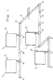
- Fig. 1 a perspective view of a heat installation according to the present invention using water to transmit heat;
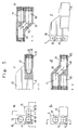
- Fig. 2 a main connection element (1) according to Fig. 1, shown in a) a sectional view, b) from the left and c) from the right in Fig. 1;
- Fig. 3 a connection element (2) according to Fig. 1, shown a) in a lateral or gable view and b) in a view from the room;
- Fig. 4 a) an inner corner element (3) and b) an outer corner element (4), seen in a lateral view and in a horizontal section respectively (c and d respectively);
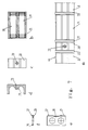
- Fig. 5 a threshold transition element, shown from the same side in two views a) and b) in order to clearly illustrate various details, view c) being a sectional view along line C-C in Fig. 5a), view d) a sectional view along line B-B in Fig. 5b), view e) a sectional view along line A-A in Fig. 5a) and view f) a perspective view from above;
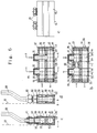
- Fig. 6 a radiator connection element in a) a vertical diametrical section in a first embodiment and b) a vertical diametrical section in a second embodiment, c) a sectional view along line I-I in Fig. 6a), d) a sectional view along line II-II in Fig. 6a) and f) a partial view from the left in Fig. 6c) or 6d);
- Fig. 7 a joint element in a) a view from the room, b) a vertical diametrical section of a joint element shell, c) a distance element, seen c) from the room and d) in a vertical section, e) a cover element to span the joints in a schematic lateral view and f) a sectional view along line A-A in Fig. 7e); and
- Fig. 8 central vertical sectional views of terminal parts for a) one-pipe-systems and b) two-pipe-systems.
- In Fig. 1 a main connection element 1 is shown, which in a way known per se is designed to be connected to main pipings (not shown) to and from e.g. a central heater (not shown) and which is shown in more detail in Fig. 2. In Fig. 3
connection elements 2 are shown in more detail and in Fig. 4inner corner elements 3 and outer corner elements 4 respectively are shown.Threshold transition elements Element 5 is shown in detail in Fig. 5. Athreshold 6 is disposed between such threshold transition elements. Aradiator connection element 8 is shown in detail in Fig. 6.Terminal parts 9 for blind loop ends are shown and in Fig. 7 ajoint element 10 is shown in detail, while in Fig. 1radiators 11 are shown, which can be conventional hot water radiators havingconventional radiator valves 12. - The heat installation shown in Fig. 1 is provided with two blind branches, it being easy to design each branch, thanks to the characterizing features of the present invention, according to individual needs at any time for an one-pipe-operation or a two-pipe-operation. It is easy to design e.g. one of the branches for one-pipe-operation and the other for two-pipe-operation, there being no need to make any exterior alterations. It is also possible, at any time, to add to the branches, i.e. extend them and/or mutually connect their ends. Also, it is easy to later on connect additional radiators and to remove existing radiators respectively from the system.
- Fig. 1 shows clearly, that a heat installation according to the invention advantageously can be designed as a basic module system or building element system, selling the various components advantageously being done in self-service outlets and an installation subsequently being done by the buyer himself, e.g. a home or an apartment owner. It is true that the majority of the components can be delivered in one single standard design as to dimensions, but it is easy to provide
connection elements 2 andthresholds 6 in various lengths, it thereby being easy and simple to accommodate them to different installation dimensions and designs, particularly because the exact location of the various components per se easily can be adjusted within certain limits thanks to the insertion principle and the relative displaceability together with maintained functions for the rest which result from it. - Main connection element 1 shown in Fig. 2 comprises an arbitrarily designed strip- or block-
shaped shell 13, which can be solid or hollow and be made of a plastic and/or metallic material having a front orroom side 14 and a rear orconnection side 15, from whichconnection pieces pipe 18 andpipe 19 respectively, which extend through the main connection element in its longitudinal direction.Pipes pipes Front side 14 andupper side 20 of the main connection element can be decoratively designed in an arbitrary way, suitably in the same way and with the same profile dimensions as the following components, which are included in the installation.Pipe 18 is of course the feed pipe for hot water andpipe 19 the return pipe for colder water. The upper pipe is e.g. the feed pipe.Pieces shell 13 and engage with closedends having flanges 21 in a somewhatbroader recess 22 on the room-side of the shell, nipples 23 and 24 respectively being secured on ends, which project from the rear side of said pieces and e.g. are provided with external threads and which allowpieces pipes openings location notches 84 of some type, which prevent a rotation, can of course also be provided in an optional place. The terminal areas ofpipes -
Connection element 2, shown in Fig. 3, comprises a shell 25 comprising e.g. a closed external housing 26, which accommodatesducts Ducts bridge portions 29 according to Fig. 3a. Also, said shell can be provided with centraltransverse control elements 30 designed as holes and/or casings for screws or the like, by means of which said elements can be fastened to e.g. awall 81. Possibly with the exception of saidcontrol elements 30 such a connection element can be made all of a piece, of a plastic and/or metallic material, e.g. aluminum, and remaining cavities can advantageously be filled with an insulatingmaterial 31 in a way known per se as regards the method. Also,ducts external bevellings 82. - In Figs. 4a and 4c an
inner corner element 32 is shown,legs outer corner element 35 according to Figs. 4b and 4d is designed in a similarfashion having legs cases pipes circumferential grooves 38, in which O-rings or the like 39 are introduced. Such corner elements are connected in a simple way to adjacent connection elements, the projecting duct ends of the latter being inserted in legs at least such a distance, that O-rings or the like 39 are passed and in this way are expanded and consequently seal. Said corner elements can also be made in one piece of a plastic and/or a metallic material. They can be made hollow according to Fig. 3a or possibly solid. -
Threshold transition element 5, shown in Fig. 5, corresponds mirror-symmetrically tothreshold transition element 7, and thus the latter will not be shown or described in more detail. It is shown thatelement 5 has an upendedportion 40, similar to the components described above and which changes into ahorizontal portion 41. The latter portion suitably is, as regards the external profile, similar tothreshold 6, and in this way an adaptation to various threshold profiles can easily be done. It is shown in the various views in Fig. 5 thatupper pipe 19 changes via an obliquely downwardly directedpassage 42 into a lower extension of the same pipe, whilelower pipe 18 via apassage 43, in an obliquely lateral direction, changes into a laterally shifted extension of the same pipe. Fig. 5e shows that the twopipes threshold transition portion 41 adjacent each other in the same horizontal plane. The same pipe orientation is used withinthreshold 6, not shown in detail, which then is connected to the mirror-symmetrically designedthreshold transition element 7, in whichpipe 19 again being disposed on top withinportion 40 or possibly, if it is desirable in a special case, at the bottom, which is easily done e.g. ifpassage 42 does not extend in a vertical plane obliquely downwardly but obliquely downwardly in a lateral direction in eitherelement lower pipe 18 continues straight ahead, in which way a reversal can be attained, which however normally probably is not required. The end openings ofpipes internal grooves 44 and O-rings or the like 45 introduced in said grooves. Also, in required places possibly screwed plugs 46,47 can be used in order to render possible a chip removal machining operation or the like. -
Radiator connection element 8, shown in Fig. 6, is mainly similar in its design to the above-described elements and comprises ashell 48, which accommodatespipes internal grooves 49 and O-rings or the like 50 introduced in said grooves. In thisway connection elements 2 can be sealingly connected in the two directions, and a longitudinal adjustment can thus be obtained. Starting from below two similar verticalcylindrical cuts 51 are disposed inshell 48, at a distance in a horizontal direction from each other and e.g. having a step-shapedexpansion element 52 at their lower ends and asimilar constriction element 53 at their upper ends, from which said cut with its smallest diameter extends outwardly through the upper side ofshell 48. In each cut 51 aninsert lower flange end 58 and 59 respectively as well asconnection pieces flanges Connection pipes 64 to aradiator 11 can then be connected to nipples 62 by means ofnuts 65 in a way known per se. -
Inserts pipes pipe 18 via a closer casing-shapedpassage 66 is intended as regards one of saidradiator connections 64. Thus, this is the case with the radiator connection element according to Fig. 6 a, which is designed for two-pipe-systems, in which one of saidradiator connections 64 is entirely connected topipe 19, while theother radiator connection 64 is entirely connected topipe 18,pipe 19 being extended round the closer casing-shapedportion 66, which is shown in Fig. 6a and d. In order to avoid that casing-shapedportion 66 detrimentally influences the flow throughpipe 19 laterally disposedrecesses 67 are designed ininsert 55, which are shown in Fig. 6a and d. The material inshell 8 possibly can also be reduced around casing-shapedportion 66, i.e. within the area ofupper pipe 19 around each cut 51, if that is required. Said inserts are around their waist suitably provided withcircumferential grooves 87 and O-rings or the like 88 introduced into said grooves. - The design according to Fig. 6b is used for one-pipe-operation, two similarly designed inserts 54 suitably being introduced into
cuts 51, while the section ofpipe 19 and/or possiblypipe 18 between said inserts is provided with a choke element 68, which it is easy to introduce in the respective pipes from either end, which choke element is shaped like a casing, suitably provided with recessed ends and en external circumferential O-ring 69, introduced into agroove 70, and suitably in this way simultaneously an advantageous friction locking can be obtained. This choke element has a passage with a reduced diameter and thus the first radiator connection, seen in the flow direction of the heat medium, is subjected to a higher pressure and consequently can function as an inlet, while the second radiator connection, subjected to a lower pressure, functions as an outlet. Of course, it is easily possible to calibrate said choke elements differently, in which way as regards a series of radiator connection elements a choking according to e.g. a falling or rising scale can be obtained.Cuts 51 and/or inserts 54,55 can be provided with rotation-preventing location notches, in order to position the various pipe sections exactly on one line. To prevent a rotation in this way is a method already known per se and thus such notches are not shown in detail. - In Fig. 7 a joint element is shown, generally designated 10, which possibly is needed between two adjacent connection elements. This element is provided with a
shell 71 having pipes, grooves and O-ring or the like according to the design illustrated above, and in order to accommodate e.g. longer projecting pipes adistance element 72 having a central recessed bore or the like 73, designed to introduce a mounting screw, not shown, can be used. The material around bore 73 can be extended inwardly in order to form alocation notch 74 designed to hold said pipes. The latter may in said joint elements, also as regards joint elements between other module elements 1-10, be surrounded bycover elements 75 having awall 76, which surrounds said pipes, and an externaljoint lip 77, which covers said joint elements outwardly. - Finally in Fig. 8
terminal parts 9 are shown, namely one terminal part for an one-pipe-system in Fig. 8a and one terminal part for a two-pipe-system in Fig. 8b. The difference is that within the terminal part for an one-pipe-system the twopipes end passage 78, while instead of such a passage adiaphragm 79 is used in the terminal part for a two-pipe-system. In the two cases there are provided at the pipe inlets circumferential recessed grooves and O-rings or the like introduced in said grooves. It is apparent, that the two terminal parts and the two designs allow blind terminal branches. The only difference is that in a two-pipe-system already in the first fed radiator the return water enters into the return piping, while a true return piping not starts until in the terminal part as regards a one-pipe-system. - The present invention is not limited to the embodiments described above and shown in the accompanying drawings. All of the components can of course be provided with e.g. a covering shell of some kind of fine wood or of any other arbitrarily selected material and configuration, and possibly quick-locking means designed in a way known per se can be used. Also, it is possible, according to the need, to make the various modules more or less heat-insulating, which has been stated above. The modules advantageously can be provided with at least one extra through cavity in their longitudinal direction, e.g. in the form of a third and a fourth pipe or piping respectively, through which cavities e.g. cooled or heated air can be transported or which can be used for wiring of e.g. electrical, tele- and/or communication wires etc. Such additional cavities only result in a very small additional cost and no extra work whatsoever during the installation work, since the same construction and assembly principle can be used as for the water pipes. Also, in particular cases it is feasible to use an extra cavity for a tap water pipe, the cavity itself being used as a tap water pipe, or a hose, preferably made of a plastic material and inserted into the cavity.
Claims (11)
- A heat installation for buildings, using water as a heat transmitting medium, which comprises two pipes (18, 19), one of which is a forward pipe and the other one a return pipe, to which pipes radiators (11) are connected, said installation being designed as a module or building element system, which comprises differently designed strip and block-shaped building elements (1-10), which are insertable in each other and with which said forward and return pipes are integrated as parts, e.g. fastened to said elements, for said radiator connection being provided special building elements (8), characterized in that said forward and return pipes (18, 19) are disposed directly one above the other in said connection elements (8), like in the majority of the other elements and;- cylindrical cuts are made through said connecting elements whereby said cuts are disposed within the plane of and extend at right angles to said pipes, and;- into which cuts inserts (54, 55) are introduced;- a first insert providing a direct connection between the radiator and the lower of said pipes, which is suitably the return pipe, via a casing-shaped passage (66) showing a reduced overall diameter in the region of the upper of said pipes and a second insert providing a direct connection from the radiator to the upper pipe which pipe continues around said casing-shaped passage (66).
- A heat installation according to claim 1, characterized in that one of the types of said building elements (1 - 10) is a main connection element (1) having a shell (13), for the rear or connection side (15) of which connection pieces (16,17) project at different levels and suitably in a horizontal direction distanced from each other, which connection pieces are connected at right angles to a return and a forward pipe respectively or corresponding channels, which extend through said main connection element in its longitudinal direction, and in that said pieces (16,17) comprise tubular elements, which extend through transverse cuts in said shell (13) and which abut with closed ends having flanges (21) a somewhat wider recess (22) on the front or local side of said shell, while on the rear side of said pieces projecting nipples (23 and 24, respectively), e.g. having ends provided with external threads, are screwed, by means of which said pieces are sealingly locked on said shell with intermediate seals or the like (80) and in that the ends of said nipples adjacent said shell preferably have a hexagonal shape, in that said pieces (16,17) have openings (82 and 83, respectively) which correspond to said channels (18,19) and in that there are location notches (84), designed in an arbitrary manner, in arbitrary areas for said pieces.
- A heat installation according to claim 1, characterized in that one of the types of said building elements (1-10) is a connection element (2) having a shell (25), which preferably comprises an external housing (26) and from the two ends of which shall pipes (27,28) project outwardly in a longitudinal direction e.g. different distances as return and forward pipes disposed the one above the other, which pipes preferably are integral with said, shell through bridge portions (29), said shell preferably also being provided with central, transverse control elements (30), designed as holes and/or casings for screws or the like, by means of which such a building element can be fastened e.g. to a wall (81), in that if said shell is hollow preferably there is a filling in the cavities of an insulating material (31), and in that said pipe ends preferably are provided with circumferential external bevellings (82) and/or in that said pipes (27,28) are designed as in the longitudinal direction and/or the circumferential direction possibly not through guide means for loosely introduced pipes, which preferably can be fastened to said shell.
- A heat installation according to claim 1, characterized in that said types of building elements (1-10) include an inner corner element (32) having legs (33, 34) and an outer corner element (35) having legs (36,37), in the end areas of said legs within said pipes (18,19) circumferential grooves (38) being arranged, in which O-rings or the like (39) have been introduced.
- A heat installation according to claim 1, characterized in that among said types of building elements (1-10) there are mirror-symmetrical to each other in pairs corresponding threshold transition elements (5,7), each one of which includes an upended portion (40), which changes into a horizontal portion (41), which preferably has the same shape as a threshold (6), in that in said upended portion (40) the upper pipe (19) via an obliquely downwardly and possibly also laterally directed passage (42) is changed into a lower extension of the same channel, while the lower channel (18) in said upended portion, via an obliquely, laterally directed or possibly straight ahead extended passage (43) changes into a laterally displaced and a straight ahead continued extension respectiely of the same channel, in that in said horizontal threshold transition portions (41) said two pipes (18,19) , as in said threshold (6), are disposed adjacent each other in the same horizontal plane, and in that the end openings of said pipes (18,19), on either side of said threshold transition elements, are provided with internal grooves (44) and O-rings or the like (45) introduced in said grooves.
- A heat installation according to claim 1, characterized in that one of said types of building elements (1-10) is a radiator connection element (8), which comprises a shell (48) , which houses said pipes (18,19), the end areas of which are provided with internal grooves (49) and O-rings or the like (50) introduced into said grooves, in that starting from below in said shell (48) there are two of the said vertical cylindrical cuts (51), which are alike and distanced from each other in a horizontal direction and preferably provided with a step-shaped expansion element (52) at their lower ends and a step-shaped constriction element (53) at their upper ends, from which said cut with a smaller diameter extends outwardly through the upper side of said shell (48), and in that in each said cut (51) and insert (54 and 55 respectively) of the said kind is inserted, which inserts have a common principal shape, namely a cylindrical body, which essentially fills said respective cut and has a lower flange (56 and 57 respectively) and an upper step-shaped end (58 and 59 respectively) as well as connection pieces (60 and 61 respectively), which project through the upper cut opening, on which pieces, which preferably are provided with external threads, suitably nipples (62) can be screwed, which via seals or the like (63) allow a sealing against said shell and said insert as well as a sealed engagement between said flanges (56,57) and the adjacent portion of said cut, preferably with intermediate seals or the like, and in that on said nipples (62) connection pipes (64) to a radiator (11) are connected by means of nuts (65).
- A heat installation according to claim 6, characterized in that said inserts (54,55) are provided with openings (85,86), which correspond to said pipes (18, 19), and as regards the shape of one of said inserts (54) there suitably exists an exact correspondence as compared to said pipes, that the said one insert (55) within the area around the casing-shaped portion (66) is provided with laterally disposed recesses (67), and in that the material in said shell (8) is reduced around said casing-shaped portion (66) in order to allow a non-reduced or less reduced heat medium flow within said area.
- A heat installation according to claim 6 or 7, characterized in that in the forward pipe (19) between the two inserts (54), which have been introduced into said shell (8), in a one-pipe-operation a casing-shaped choke element (68) has been inserted, which is provided with an external circumferential groove (70) and an O-ring or the like (69) introduced into said groove in order to allow a sealing and/or a friction locking, and in that there are differently calibrated choke elements, which are arranged after one another in the flow direction, an in that said cuts (51) and/or said inserts (54, 55) are provided with rotation-preventing location notches.
- A heat installation according to claim 1, characterized in that one of said types of building elements (1-10) is a joint element (10), designed to be placed between two adjacent connection elements (2), which joint element comprises a shell (71) having pipes (18, 19) and preferably internal grooves and O-rings or the like introduced in said grooves, in that said joint element also comprises a distance portion (72) having a central recessed bore or the like (73) in order to be able to introduce a fastening screw or the like, the material around said bore (73) being extended inwardly in order to form a location notch (74), designed to retain said pipes (27, 28) and in that in the joints, also as regards joints between other building elements (1-10), cover elements (75) are arranged, having a wall (76), which surrounds said pipes (27, 28), as well as an external joint lip (77), which is designed to cover said joints outwardly.
- A heat installation according to claim 1, characterized in that among said types of building elements (1-10) there are terminal parts (9), namely one terminal part for one one-pipe-system including an end passage (78), which connects said two pipes (18, 19) with each other within said terminal part, as well as one terminal part for one two-pipe-system, in which said two pipes (18, 19) within said terminal part are separated from each other by means of a diaphragm (19); and in said two cases there are also circumferential recessed grooves arranged at the pipe inlets and O-rings or the like introduced in said grooves.
- A heat installation according to claim 1, characterized in that said building elements are provided with at least one in the longitudinal direction through additional cavity, designed as a third or fourth channel or pipe with the same construction and assembly principle as for said forward and return pipes, e.g. for transport of air and/or water, possibly in a cooled and heated state, respectively, or wiring, e.g. for electricity, tele and communication.
Priority Applications (1)
| Application Number | Priority Date | Filing Date | Title |
|---|---|---|---|
| AT8989902180T ATE105067T1 (en) | 1988-02-05 | 1989-02-06 | HEATING SYSTEM FOR BUILDINGS WITH HOT WATER. |
Applications Claiming Priority (3)
| Application Number | Priority Date | Filing Date | Title |
|---|---|---|---|
| DE8801457U | 1988-02-05 | ||
| DE8801457 | 1988-02-05 | ||
| PCT/SE1989/000045 WO1989007224A1 (en) | 1988-02-05 | 1989-02-06 | A heat installation for premises with water as a heat transmitting medium |
Publications (2)
| Publication Number | Publication Date |
|---|---|
| EP0401237A1 EP0401237A1 (en) | 1990-12-12 |
| EP0401237B1 true EP0401237B1 (en) | 1994-04-27 |
Family
ID=6820351
Family Applications (1)
| Application Number | Title | Priority Date | Filing Date |
|---|---|---|---|
| EP89902180A Expired - Lifetime EP0401237B1 (en) | 1988-02-05 | 1989-02-06 | A heat installation for premises with water as a heat transmitting medium |
Country Status (4)
| Country | Link |
|---|---|
| US (1) | US5111875A (en) |
| EP (1) | EP0401237B1 (en) |
| DE (1) | DE68914987T2 (en) |
| WO (1) | WO1989007224A1 (en) |
Families Citing this family (17)
| Publication number | Priority date | Publication date | Assignee | Title |
|---|---|---|---|---|
| DE59103894D1 (en) * | 1990-11-15 | 1995-01-26 | Rafeld Kunststofftechnik Gmbh | Sanitary and heating pipe system, consisting entirely or predominantly of plastic, in particular polypropylene, for the water supply. |
| US5361981A (en) * | 1993-04-21 | 1994-11-08 | Heat Exchangers, Inc. | Air conditioning unit |
| SE502732C2 (en) * | 1993-05-19 | 1995-12-18 | Thermopanel Ab | Connection piece for hot water radiators |
| IL109269A (en) * | 1994-04-10 | 1996-10-31 | Magen Plastic | Heat exchanger |
| IT241174Y1 (en) * | 1996-09-23 | 2001-05-03 | Babusci Franco | MULTI-DIRECTIONAL COLLECTOR-DISTRIBUTOR OF FLUIDS |
| DE19806157C2 (en) * | 1998-02-14 | 2003-04-17 | Herbert Schwarz | Kit for creating a water-bearing piping system |
| US6848267B2 (en) * | 2002-07-26 | 2005-02-01 | Tas, Ltd. | Packaged chilling systems for building air conditioning and process cooling |
| US6769258B2 (en) | 1999-08-06 | 2004-08-03 | Tom L. Pierson | System for staged chilling of inlet air for gas turbines |
| EP1108960A3 (en) * | 1999-12-17 | 2003-01-02 | Noboru Maruyama | Heat supply system |
| NL1017645C2 (en) | 2001-03-19 | 2002-09-26 | Brinic B V | Mounting assembly and mounting block for a central heating system. |
| US7191789B2 (en) * | 2003-05-02 | 2007-03-20 | Inventive Development L.L.C. | Transition adaptor and component modules for hydronic heating |
| ITBL20030007A1 (en) * | 2003-05-30 | 2004-11-30 | Rold Adelio Da | HEATING SYSTEM WITH VECTOR FLUID DISTRIBUTED IN FINISHED FLOORING PLANKS. |
| GB2471797B (en) * | 2005-10-17 | 2011-04-20 | Lee Mckeith | Central heating system - endstop valve |
| FI122288B (en) * | 2006-10-03 | 2011-11-15 | Halton Oy | Device for the treatment of room air |
| US8251021B1 (en) | 2007-02-02 | 2012-08-28 | Inventive Development Llc | Hydronic assembly of manifold with hydraulic separator and endsuction pumps |
| US10767561B2 (en) | 2014-10-10 | 2020-09-08 | Stellar Energy Americas, Inc. | Method and apparatus for cooling the ambient air at the inlet of gas combustion turbine generators |
| US10808615B2 (en) | 2015-09-04 | 2020-10-20 | Stellar Energy Americas, Inc. | Modular chiller plant |
Family Cites Families (21)
| Publication number | Priority date | Publication date | Assignee | Title |
|---|---|---|---|---|
| US1663271A (en) * | 1924-04-03 | 1928-03-20 | Kehm August | Pipe fitting |
| US1770813A (en) * | 1928-04-09 | 1930-07-15 | William B Selzer | Air-tempering apparatus |
| US2072427A (en) * | 1935-05-02 | 1937-03-02 | American Blower Corp | Air conditioning system |
| US2113775A (en) * | 1937-03-22 | 1938-04-12 | Vapor Car Heating Co Inc | Vapor heating system |
| US2500642A (en) * | 1945-11-09 | 1950-03-14 | Stanley H Morse | Heating system |
| US2486141A (en) * | 1946-10-10 | 1949-10-25 | Mel Products Company | Diversion fitting for hot-water heating systems |
| US2573539A (en) * | 1946-12-04 | 1951-10-30 | John T Bryce | Radiator |
| US2835186A (en) * | 1954-06-01 | 1958-05-20 | Whirlpool Co | Air conditioning system |
| BE655435A (en) * | 1963-11-06 | |||
| FR1537724A (en) * | 1966-05-23 | 1968-08-30 | Wirsbo Bruks Ab | Common heating system for multi-storey buildings |
| DE1775636A1 (en) * | 1968-09-04 | 1971-09-16 | Kabel Metallwerke Ghh | Arrangement for the production of a branch or connection point of pipelines |
| FR2320507A1 (en) * | 1975-08-07 | 1977-03-04 | Lecomte Robert | Water pipe for central heating - is made integrally with skirting and has square section tube on hollow rectangular section with service pipe support brackets |
| DE2635903A1 (en) * | 1976-08-10 | 1978-02-16 | Hagmeyer Max Jakob | Hollow wall or floor heating system - uses hollow bricks and standard bricks with set of connecting fittings |
| DE2705117A1 (en) * | 1977-02-08 | 1978-08-10 | Albert Emmer | Fitting for heating radiator flow connections - has housings inserted and connected by pressing and screw couplings |
| DE2723556A1 (en) * | 1977-05-25 | 1978-11-30 | Meibes | Multiway pipe junction piece - accommodates all pipes with outlets in min space without head loss |
| SE436446B (en) * | 1977-06-08 | 1984-12-10 | Elpan Aps | panel radiator |
| EP0008544A1 (en) * | 1978-08-25 | 1980-03-05 | CROSS & McCARTHY LIMITED | Method of installing conduit and conduit means suitable therefor |
| DE2843818A1 (en) * | 1978-10-07 | 1980-04-17 | Balsfulland Maschfabrik Gmbh | Underfloor heating system heating medium distributor - has through channels for main flow and side outlets for heating circuits |
| DE2920472A1 (en) * | 1979-05-21 | 1980-11-27 | Klaesener Presswerk Gmbh | Floor-heater plate construction - has i=shaped unions with branch passages connected to those inside it |
| DE3439585A1 (en) * | 1984-10-30 | 1986-04-30 | Danfoss A/S, Nordborg | CONNECTING DEVICE FOR A RADIATOR |
| DE3533460A1 (en) * | 1985-09-19 | 1987-03-26 | Tuxhorn Kg Geb | Device for distributing flow- and return-water in water-heating installations |
-
1989
- 1989-02-06 WO PCT/SE1989/000045 patent/WO1989007224A1/en active IP Right Grant
- 1989-02-06 EP EP89902180A patent/EP0401237B1/en not_active Expired - Lifetime
- 1989-02-06 DE DE68914987T patent/DE68914987T2/en not_active Expired - Fee Related
- 1989-02-06 US US07/548,981 patent/US5111875A/en not_active Expired - Fee Related
Also Published As
| Publication number | Publication date |
|---|---|
| DE68914987D1 (en) | 1994-06-01 |
| DE68914987T2 (en) | 1994-12-01 |
| WO1989007224A1 (en) | 1989-08-10 |
| US5111875A (en) | 1992-05-12 |
| EP0401237A1 (en) | 1990-12-12 |
Similar Documents
| Publication | Publication Date | Title |
|---|---|---|
| EP0401237B1 (en) | A heat installation for premises with water as a heat transmitting medium | |
| US3821818A (en) | Prefabricated bathroom walls | |
| US8281800B2 (en) | Faucet mounting sleeve | |
| US7566264B2 (en) | Small duct high velocity damper assembly | |
| US7699117B2 (en) | Fire protection sprinkler system and related apparatus | |
| US20050188632A1 (en) | Modular core wall construction system | |
| US5743327A (en) | Radiator system | |
| US20030056826A1 (en) | Modular plumbing system | |
| USRE36539E (en) | Seal and installation improvements | |
| LV10529B (en) | Radiant or radiant/ventilating air-conditioning prefabricated elements and air-conditioning installation including said elements | |
| GB2166466A (en) | Replacement conduits | |
| KR100886361B1 (en) | Box for water pipe connecter | |
| EP0008544A1 (en) | Method of installing conduit and conduit means suitable therefor | |
| KR20080099064A (en) | Apparatus of water pipe connecter and chamber and box for water pipe connecter | |
| KR200304064Y1 (en) | Sleeve and Indoor Cover for Pipe Laying of Airconditioner | |
| CA2546748A1 (en) | Slip joint double y apparatus and method | |
| GB2600546A (en) | Structural insulated panel for use in buildings | |
| WO2006109080A2 (en) | Central heating system | |
| EP1174557A1 (en) | Method for erecting a building and building element | |
| CN213839990U (en) | Embedded part for mounting shower valve | |
| KR101461645B1 (en) | bury type piping joint-box for of air-conditioner | |
| CZ284422B6 (en) | Connecting device for heating bodies | |
| KR200321072Y1 (en) | Sleeve and Indoor Cover for Pipe Laying of Airconditioner | |
| KR200275715Y1 (en) | A Piping Fitting Method for Separation-type Air Conditioner with Buried-piping | |
| CN100371654C (en) | Connection fitting for heating body and method for fixing connection fitting on heating body |
Legal Events
| Date | Code | Title | Description |
|---|---|---|---|
| PUAI | Public reference made under article 153(3) epc to a published international application that has entered the european phase |
Free format text: ORIGINAL CODE: 0009012 |
|
| 17P | Request for examination filed |
Effective date: 19900724 |
|
| AK | Designated contracting states |
Kind code of ref document: A1 Designated state(s): AT BE CH DE FR GB IT LI NL SE |
|
| 17Q | First examination report despatched |
Effective date: 19910730 |
|
| GRAA | (expected) grant |
Free format text: ORIGINAL CODE: 0009210 |
|
| AK | Designated contracting states |
Kind code of ref document: B1 Designated state(s): AT BE CH DE FR GB IT LI NL SE |
|
| PG25 | Lapsed in a contracting state [announced via postgrant information from national office to epo] |
Ref country code: IT Free format text: LAPSE BECAUSE OF FAILURE TO SUBMIT A TRANSLATION OF THE DESCRIPTION OR TO PAY THE FEE WITHIN THE PRE;WARNING: LAPSES OF ITALIAN PATENTS WITH EFFECTIVE DATE BEFORE 2007 MAY HAVE OCCURRED AT ANY TIME BEFORE 2007. THE CORRECT EFFECTIVE DATE MAY BE DIFFERENT FROM THE ONE RECORDED.SCRIBED TIME-LIMIT Effective date: 19940427 Ref country code: NL Effective date: 19940427 Ref country code: AT Effective date: 19940427 |
|
| REF | Corresponds to: |
Ref document number: 105067 Country of ref document: AT Date of ref document: 19940515 Kind code of ref document: T |
|
| REF | Corresponds to: |
Ref document number: 68914987 Country of ref document: DE Date of ref document: 19940601 |
|
| ET | Fr: translation filed | ||
| NLV1 | Nl: lapsed or annulled due to failure to fulfill the requirements of art. 29p and 29m of the patents act | ||
| EAL | Se: european patent in force in sweden |
Ref document number: 89902180.2 |
|
| PLBE | No opposition filed within time limit |
Free format text: ORIGINAL CODE: 0009261 |
|
| STAA | Information on the status of an ep patent application or granted ep patent |
Free format text: STATUS: NO OPPOSITION FILED WITHIN TIME LIMIT |
|
| 26N | No opposition filed | ||
| PGFP | Annual fee paid to national office [announced via postgrant information from national office to epo] |
Ref country code: GB Payment date: 19951227 Year of fee payment: 8 |
|
| PGFP | Annual fee paid to national office [announced via postgrant information from national office to epo] |
Ref country code: CH Payment date: 19960105 Year of fee payment: 8 |
|
| PGFP | Annual fee paid to national office [announced via postgrant information from national office to epo] |
Ref country code: BE Payment date: 19960108 Year of fee payment: 8 |
|
| PGFP | Annual fee paid to national office [announced via postgrant information from national office to epo] |
Ref country code: FR Payment date: 19960116 Year of fee payment: 8 |
|
| PGFP | Annual fee paid to national office [announced via postgrant information from national office to epo] |
Ref country code: DE Payment date: 19960416 Year of fee payment: 8 |
|
| PG25 | Lapsed in a contracting state [announced via postgrant information from national office to epo] |
Ref country code: GB Effective date: 19970206 |
|
| PG25 | Lapsed in a contracting state [announced via postgrant information from national office to epo] |
Ref country code: LI Effective date: 19970228 Ref country code: BE Effective date: 19970228 Ref country code: CH Effective date: 19970228 |
|
| BERE | Be: lapsed |
Owner name: HAMMARSTEDT CURT Effective date: 19970228 |
|
| GBPC | Gb: european patent ceased through non-payment of renewal fee |
Effective date: 19970206 |
|
| REG | Reference to a national code |
Ref country code: CH Ref legal event code: PL |
|
| PG25 | Lapsed in a contracting state [announced via postgrant information from national office to epo] |
Ref country code: FR Effective date: 19971030 |
|
| PG25 | Lapsed in a contracting state [announced via postgrant information from national office to epo] |
Ref country code: DE Effective date: 19971101 |
|
| REG | Reference to a national code |
Ref country code: FR Ref legal event code: ST |
|
| PGFP | Annual fee paid to national office [announced via postgrant information from national office to epo] |
Ref country code: SE Payment date: 19991208 Year of fee payment: 12 |
|
| PG25 | Lapsed in a contracting state [announced via postgrant information from national office to epo] |
Ref country code: SE Free format text: LAPSE BECAUSE OF NON-PAYMENT OF DUE FEES Effective date: 20010207 |
|
| EUG | Se: european patent has lapsed |
Ref document number: 89902180.2 |