US1663271A - Pipe fitting - Google Patents
Pipe fitting Download PDFInfo
- Publication number
- US1663271A US1663271A US53515A US5351525A US1663271A US 1663271 A US1663271 A US 1663271A US 53515 A US53515 A US 53515A US 5351525 A US5351525 A US 5351525A US 1663271 A US1663271 A US 1663271A
- Authority
- US
- United States
- Prior art keywords
- main
- pipe fitting
- fitting
- threaded
- plug
- Prior art date
- Legal status (The legal status is an assumption and is not a legal conclusion. Google has not performed a legal analysis and makes no representation as to the accuracy of the status listed.)
- Expired - Lifetime
Links
- XLYOFNOQVPJJNP-UHFFFAOYSA-N water Substances O XLYOFNOQVPJJNP-UHFFFAOYSA-N 0.000 description 9
- 238000010438 heat treatment Methods 0.000 description 3
- 238000010276 construction Methods 0.000 description 1
- 230000002035 prolonged effect Effects 0.000 description 1
- 238000004904 shortening Methods 0.000 description 1
Images
Classifications
-
- F—MECHANICAL ENGINEERING; LIGHTING; HEATING; WEAPONS; BLASTING
- F24—HEATING; RANGES; VENTILATING
- F24D—DOMESTIC- OR SPACE-HEATING SYSTEMS, e.g. CENTRAL HEATING SYSTEMS; DOMESTIC HOT-WATER SUPPLY SYSTEMS; ELEMENTS OR COMPONENTS THEREFOR
- F24D19/00—Details
- F24D19/0002—Means for connecting central heating radiators to circulation pipes
- F24D19/0004—In a one pipe system
Definitions
- the invention relates to'pipe fitting and has for its principal objects to provide a connection that Will facilitate tle fiow of water from a main to a lateral and from a lateral to a main and-to provide a fitting that may be readily combined with conventional threeway joints to produce that result.
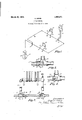
- FIG. 1 is a diagrammatical view of a single pipe hot water heating system
- Fig. 2 is a detail vievv illustrating the joints between the main and the risers
- Fig. 3 is an enlarged sectional view of a conventional T-joint equipped with a fitting according to this invention.
- Fig. 4 is a longitudinal sectional view of a one-piece fitting embodying the elements of a conventional T-joint and this invention.
- Fig. l 10 indicates a boiler, 11 a main connected with the boiler at the top and the bottom; 12, 13 and 14 radiators connected with the main by supply risers 15, 16, and 17, and return risers 18, 19 and 20, respectively.
- the connections between the risers and the main are usually made by inserting conventional T-joints 21 and 22.
- This practice can be continued with the present invention by shortening the intermediate length of main 23 and inserting two fittings made according to this invention and illustrated in Fig. 2, at 24 and l25.
- These fittings include a threaded portion 26 adapted to thread into one'of the opposed threaded sockets 27 of the conventional T. Adjacent to this threaded portion is an enlargement 28 equipped with ⁇ a suitable wrench Serial No. 703,909. Divided and this application med August 31,
- the plug In the case of the lsupply riser the plug is set with its axis below the axis of the main and in the case of the return riser, the plug is set with its axis above the axis of the mam. Tater approaching from the right 1n Fig. 2 passes into the T 21, and meets the obstruction formed by the plug with the result that the water readily flows up the supply riser and into the radiator. 30 of the plug is smaller than that of the main and permits a portion only of the water to pass on in the direction of the arrow 32.
- the fitting can be stocked as other fittings and readily assembled with conventional fitings for a great variety of purposes.
- the illustration here' given for converting a conventional T into a special fitting for hot Water heating systems is sufiicient to show how the device is to be used in practice, and those skilled in the art will readily make other applications out of it.
- a pipe fitting having opposed openings of the same size in substantial alignment and an intermediately disposed lateral opening directed transversely to the opposed openingsan obstruction between one of the opposed openings and the intermediate open- The bore ing, and a single eccentric tube carried by the obstruction and extending towards the other opposed opening.
- A. pipe fitting having opposed threaded 5 openings of the same size and a lateral opening between them, a hollow plug threaded into one of the opposed openings ⁇ and including a single eccentric tublar portion' extending inwardly across the lateral opening, and an outer portion having an internally threaded bore of the seme diameter as the bore in which the plug is threaded.
Landscapes
- Engineering & Computer Science (AREA)
- Physics & Mathematics (AREA)
- Thermal Sciences (AREA)
- Chemical & Material Sciences (AREA)
- Combustion & Propulsion (AREA)
- Mechanical Engineering (AREA)
- General Engineering & Computer Science (AREA)
- Steam Or Hot-Water Central Heating Systems (AREA)
Description
March 20, 1928. 1,663,271
A. KEHM PIPE FITTINGI original' Filed April s. 1924 Patented Mar. 20, 1928.
, AUGUST XEHM, OIEl CHICAGO, ILLINOIS.
PIPE FITTING.
Original application filed April 3, 1924,
This is a division of my applicati'onnow pending, Serial No. 703,909, filed April 3, 1924, on hot Water heatmg system.
The invention relates to'pipe fitting and has for its principal objects to provide a connection that Will facilitate tle fiow of water from a main to a lateral and from a lateral to a main and-to provide a fitting that may be readily combined with conventional threeway joints to produce that result.
In a conventional hot water heating system where a supply riser and a return riser` connect a main and a radiator it is necessary to space the joints between the respective risers and the main four to six feet apart in order to get the required flow through the radiator. This invention permits those joints to be spaced-at any convenient distance. v
Other objects and advantages of the invention will become apparent as the description is read in connection with the accompanying drawings, in which Fig. 1 is a diagrammatical view of a single pipe hot water heating system,
Fig. 2 is a detail vievv illustrating the joints between the main and the risers,
Fig. 3 is an enlarged sectional view of a conventional T-joint equipped with a fitting according to this invention, and
Fig. 4 is a longitudinal sectional view of a one-piece fitting embodying the elements of a conventional T-joint and this invention.
.Referring to Fig. l, 10 indicates a boiler, 11 a main connected with the boiler at the top and the bottom; 12, 13 and 14 radiators connected with the main by supply risers 15, 16, and 17, and return risers 18, 19 and 20, respectively. The connections between the risers and the main are usually made by inserting conventional T- joints 21 and 22. This practice can be continued with the present invention by shortening the intermediate length of main 23 and inserting two fittings made according to this invention and illustrated in Fig. 2, at 24 and l25. These fittings include a threaded portion 26 adapted to thread into one'of the opposed threaded sockets 27 of the conventional T. Adjacent to this threaded portion is an enlargement 28 equipped with `a suitable wrench Serial No. 703,909. Divided and this application med August 31,
1925. Serial No. 53,515.
seat. This enlargement is counter bored and threaded at 29 in substantial duplication of the sockets 27 and concentric therewith when assembled in the relation shown. The bore of the plug 30 beyond this counter bore is eccentric with respect to the counter bore and the threaded portion 26, and is prolonged by a tubular extension 31.
In the case of the lsupply riser the plug is set with its axis below the axis of the main and in the case of the return riser, the plug is set with its axis above the axis of the mam. Tater approaching from the right 1n Fig. 2 passes into the T 21, and meets the obstruction formed by the plug with the result that the water readily flows up the supply riser and into the radiator. 30 of the plug is smaller than that of the main and permits a portion only of the water to pass on in the direction of the arrow 32. At the return riser the water passing through the intermediate section 23 of the main will be hotter than that returning from the riser to the main, and the tubular extension 31 will direct it along the upper side of the main while permitting the cooler water to follow its natural tendency to descend to the bottom of the main with less than normal resistance.
f The fitting can be stocked as other fittings and readily assembled with conventional fitings for a great variety of purposes. The illustration here' given for converting a conventional T into a special fitting for hot Water heating systems is sufiicient to show how the device is to be used in practice, and those skilled in the art will readily make other applications out of it.
It is not essential that the fitting 24 and 25 be separate from the T-joint and in some cases it is desirable to have them made in one piece. Such a construction is shown in Fig. 4 in which corresponding parts are indicated by tlie same reference numerals.
I claim as my invention:
1. A pipe fitting having opposed openings of the same size in substantial alignment and an intermediately disposed lateral opening directed transversely to the opposed openingsan obstruction between one of the opposed openings and the intermediate open- The bore ing, and a single eccentric tube carried by the obstruction and extending towards the other opposed opening.
2. A. pipe fitting having opposed threaded 5 openings of the same size and a lateral opening between them, a hollow plug threaded into one of the opposed openings `and including a single eccentric tublar portion' extending inwardly across the lateral opening, and an outer portion having an internally threaded bore of the seme diameter as the bore in which the plug is threaded.
In testimony whereof I aix my signature. f'
AUGUST KEHM.
Priority Applications (1)
| Application Number | Priority Date | Filing Date | Title |
|---|---|---|---|
| US53515A US1663271A (en) | 1924-04-03 | 1925-08-31 | Pipe fitting |
Applications Claiming Priority (2)
| Application Number | Priority Date | Filing Date | Title |
|---|---|---|---|
| US70390924A | 1924-04-03 | 1924-04-03 | |
| US53515A US1663271A (en) | 1924-04-03 | 1925-08-31 | Pipe fitting |
Publications (1)
| Publication Number | Publication Date |
|---|---|
| US1663271A true US1663271A (en) | 1928-03-20 |
Family
ID=26731948
Family Applications (1)
| Application Number | Title | Priority Date | Filing Date |
|---|---|---|---|
| US53515A Expired - Lifetime US1663271A (en) | 1924-04-03 | 1925-08-31 | Pipe fitting |
Country Status (1)
| Country | Link |
|---|---|
| US (1) | US1663271A (en) |
Cited By (7)
| Publication number | Priority date | Publication date | Assignee | Title |
|---|---|---|---|---|
| US4305429A (en) * | 1978-11-22 | 1981-12-15 | Framatome | Coupling for two conduits |
| FR2662492A1 (en) * | 1990-05-28 | 1991-11-29 | Brezillon Andre | Device for connecting central heating radiators into a monotubular installation |
| US5111875A (en) * | 1988-02-05 | 1992-05-12 | Curt Hammarstedt | Modular heat installation for premises with water as a heat transmitting medium |
| US5331996A (en) * | 1993-10-08 | 1994-07-26 | Ziehm Raymond G | Dual mode hot water circulation apparatus |
| US6474561B2 (en) * | 1999-12-17 | 2002-11-05 | Noboru Maruyama | Heat supply system |
| EP2592191A3 (en) * | 2011-11-08 | 2014-12-31 | VIEGA GmbH & Co. KG | Tubular connection element |
| DE202020000955U1 (en) | 2020-03-06 | 2021-06-10 | Gebr. Kemper Gmbh + Co. Kg | Device for flow division |
-
1925
- 1925-08-31 US US53515A patent/US1663271A/en not_active Expired - Lifetime
Cited By (7)
| Publication number | Priority date | Publication date | Assignee | Title |
|---|---|---|---|---|
| US4305429A (en) * | 1978-11-22 | 1981-12-15 | Framatome | Coupling for two conduits |
| US5111875A (en) * | 1988-02-05 | 1992-05-12 | Curt Hammarstedt | Modular heat installation for premises with water as a heat transmitting medium |
| FR2662492A1 (en) * | 1990-05-28 | 1991-11-29 | Brezillon Andre | Device for connecting central heating radiators into a monotubular installation |
| US5331996A (en) * | 1993-10-08 | 1994-07-26 | Ziehm Raymond G | Dual mode hot water circulation apparatus |
| US6474561B2 (en) * | 1999-12-17 | 2002-11-05 | Noboru Maruyama | Heat supply system |
| EP2592191A3 (en) * | 2011-11-08 | 2014-12-31 | VIEGA GmbH & Co. KG | Tubular connection element |
| DE202020000955U1 (en) | 2020-03-06 | 2021-06-10 | Gebr. Kemper Gmbh + Co. Kg | Device for flow division |
Similar Documents
| Publication | Publication Date | Title |
|---|---|---|
| US1663271A (en) | Pipe fitting | |
| US1802766A (en) | Pipe or tube joint | |
| US2521462A (en) | Water heater | |
| US2357156A (en) | Radiator | |
| DK151057B (en) | HEAT EXCHANGES WITH A NUMBER OF INTERNAL ROWS PLACED IN AN Outer ROW | |
| US939759A (en) | Steam-generator. | |
| US598327A (en) | Water-heating system | |
| US2051311A (en) | Hot water heater | |
| US1682550A (en) | Pressure-controlling liquid seal | |
| US1811406A (en) | Pressure equalizing means for heating systems | |
| US1924900A (en) | Symmetrical heating unit | |
| US1447550A (en) | Boiler appliance | |
| US1951752A (en) | Boiler economizer | |
| US525958A (en) | Circulating tubular boiler | |
| US663575A (en) | Water-tube boiler. | |
| US977202A (en) | Radiator. | |
| US1026236A (en) | Hot-water heating system. | |
| US1552289A (en) | Feed-water heater | |
| US2045669A (en) | Pipe fitting | |
| DE670657C (en) | Gravity hot water heating system | |
| US1091625A (en) | Attachment for hot-water radiators. | |
| US1335799A (en) | Pipe-coil | |
| US920140A (en) | Water-tube boiler. | |
| US2314667A (en) | Circulating unit | |
| US1973721A (en) | Steam temperature regulator |