EP0399862A1 - Vorrichtung zur Raketensteuerung - Google Patents
Vorrichtung zur Raketensteuerung Download PDFInfo
- Publication number
- EP0399862A1 EP0399862A1 EP90401201A EP90401201A EP0399862A1 EP 0399862 A1 EP0399862 A1 EP 0399862A1 EP 90401201 A EP90401201 A EP 90401201A EP 90401201 A EP90401201 A EP 90401201A EP 0399862 A1 EP0399862 A1 EP 0399862A1
- Authority
- EP
- European Patent Office
- Prior art keywords
- missile
- sight
- line
- field
- mirror
- Prior art date
- Legal status (The legal status is an assumption and is not a legal conclusion. Google has not performed a legal analysis and makes no representation as to the accuracy of the status listed.)
- Granted
Links
Images

Classifications
-
- G—PHYSICS
- G02—OPTICS
- G02B—OPTICAL ELEMENTS, SYSTEMS OR APPARATUS
- G02B6/00—Light guides; Structural details of arrangements comprising light guides and other optical elements, e.g. couplings
- G02B6/24—Coupling light guides
- G02B6/26—Optical coupling means
- G02B6/34—Optical coupling means utilising prism or grating
-
- F—MECHANICAL ENGINEERING; LIGHTING; HEATING; WEAPONS; BLASTING
- F41—WEAPONS
- F41G—WEAPON SIGHTS; AIMING
- F41G7/00—Direction control systems for self-propelled missiles
- F41G7/20—Direction control systems for self-propelled missiles based on continuous observation of target position
- F41G7/30—Command link guidance systems
- F41G7/301—Details
- F41G7/303—Sighting or tracking devices especially provided for simultaneous observation of the target and of the missile
-
- G—PHYSICS
- G01—MEASURING; TESTING
- G01S—RADIO DIRECTION-FINDING; RADIO NAVIGATION; DETERMINING DISTANCE OR VELOCITY BY USE OF RADIO WAVES; LOCATING OR PRESENCE-DETECTING BY USE OF THE REFLECTION OR RERADIATION OF RADIO WAVES; ANALOGOUS ARRANGEMENTS USING OTHER WAVES
- G01S3/00—Direction-finders for determining the direction from which infrasonic, sonic, ultrasonic or electromagnetic waves, or particle emission, not having a directional significance, are being received
- G01S3/78—Direction-finders for determining the direction from which infrasonic, sonic, ultrasonic or electromagnetic waves, or particle emission, not having a directional significance, are being received using electromagnetic waves other than radio waves
- G01S3/782—Systems for determining direction or deviation from predetermined direction
- G01S3/785—Systems for determining direction or deviation from predetermined direction using adjustment of orientation of directivity characteristics of a detector or detector system to give a desired condition of signal derived from that detector or detector system
- G01S3/786—Systems for determining direction or deviation from predetermined direction using adjustment of orientation of directivity characteristics of a detector or detector system to give a desired condition of signal derived from that detector or detector system the desired condition being maintained automatically
-
- G—PHYSICS
- G01—MEASURING; TESTING
- G01S—RADIO DIRECTION-FINDING; RADIO NAVIGATION; DETERMINING DISTANCE OR VELOCITY BY USE OF RADIO WAVES; LOCATING OR PRESENCE-DETECTING BY USE OF THE REFLECTION OR RERADIATION OF RADIO WAVES; ANALOGOUS ARRANGEMENTS USING OTHER WAVES
- G01S3/00—Direction-finders for determining the direction from which infrasonic, sonic, ultrasonic or electromagnetic waves, or particle emission, not having a directional significance, are being received
- G01S3/78—Direction-finders for determining the direction from which infrasonic, sonic, ultrasonic or electromagnetic waves, or particle emission, not having a directional significance, are being received using electromagnetic waves other than radio waves
- G01S3/782—Systems for determining direction or deviation from predetermined direction
- G01S3/789—Systems for determining direction or deviation from predetermined direction using rotating or oscillating beam systems, e.g. using mirrors, prisms
Definitions
- the invention relates to a missile rallying device.
- a conventional weapon system includes a missile launch pad, a target tracking device, and a missile rally device.
- the target tracking device can be of the radar type or of the optoelectronic type, but in all cases it covers a narrow field.
- a missile is fired from a ramp which is located some distance from the target tracking device.
- the trajectory of the missile at start-up is relatively random, even if the direction of the launching ramp is perfectly parallel to the line of sight of the tracking device, in the direction of the target.
- the missile is unlikely to enter the narrow field covered by the target tracking device. It is therefore necessary to provide a so-called missile rallying device, having a wide field of acquisition, to locate the missile as soon as it leaves the launching pad and determine the coordinates making it possible to rally the missile on the line of sight of the device. target tracking.
- the missile is conventionally rallied either by remote control or by a steering beam.
- the known missile rallying devices are of the wide angle radar type, or of the laser director beam type, or of the pseudo-imaging or infrared imaging type.
- Pseudo-imaging, or infrared imaging locate the missile by infrared radiation from the nozzle. They include an optomechanical scanning device, and one or more photosensitive sensors in the infrared range. For example, the optomechanical device scans the image of an acquisition field having an angular width of 10 °, in the form of a square image which is analyzed in 100 ⁇ 100 pixels.
- a video signal resulting from this analysis is applied to electronic processing means to detect the presence of the missile and determine its coordinates relative to a reference point centered in the center of the image. These coordinates reflect the angular difference between the direction in which the missile is located and a line of sight common to the rallying device and the target tracking device. Because these known rallying devices analyze the entire acquisition field, which is wide, the scanning must be rapid and the bandwidth of the electronic processing means must therefore be wide. This decreases the sensitivity of the device, because of the noise, and therefore reduces the range of the rallying device, or else requires image analysis and processing means, which are more complex to obtain a large range.
- the missile is always at the edge of the field at the start of the flight, and in the center of the field at the end of the flight, so a large part of the field which is distant from the part where the missile is located is analyzed unnecessarily, this which makes the rallying device sensitive to the presence of the sun or the presence of decoys.
- the object of the invention is to propose a rallying device, of the imaging or pseudo-imaging type, which is simpler than the known devices, while having a greater range, and which is less sensitive to the presence of the sun or lures.
- the object of the invention is a rallying device which exploits the fact that the missile always enters the field of acquisition from the periphery of this field. It therefore suffices to analyze an acquisition field such that its section, by a plane perpendicular to the line of sight, has the shape of a ring, the central zone being a blind zone, and having a variable diameter as and as the missile approaches the line of sight. The diameter being wide at the time of departure, the missile is forced to return to the field, then a reduction in diameter makes it possible to preserve the missile in the field, while avoiding, in many cases, the presence of the sun or decoys.
- the acquisition field covers a lower solid angle than the known devices, which corresponds to a smaller number of analyzed pixels. Consequently, the bandwidth of the electronic processing means can be reduced.
- the signal to noise ratio is therefore better than in known devices.
- the range of the device according to the invention is therefore greater, under the same conditions of acquisition of a missile.
- a missile rallying device for determining coordinates translating the angular difference between the direction where a missile is located and a line of sight where a target is located, comprising: a photosensitive sensor, means for projecting an image on this sensor and scan the image with this sensor, means for producing a signal translating the angular difference from signals supplied by the sensor, is characterized in that the means for projecting and scanning an image, cover a field whose section, by a plane perpendicular to the line of sight, is a ring having a variable diameter as a function of the angular difference between the direction where is located the missile and the line of sight.
- the rallying device includes a spectral filtering device in the vicinity of 4.4 microns, making it possible to possibly reduce the sensitivity to the presence of the sun and to the presence of decoys, when the sun or a lure is present in the field of acquisition.
- FIG. 1 represents a missile 1 which is fired by a launching ramp 5, in the direction of a target 2, this target being pursued by a target tracking device situated in a firing station 6 which is integral with the ramp of launching 5.
- the launching pad guides the missile in a direction parallel to the line of sight LV of the target tracking device, but vagaries cause a certain angular difference ⁇ between the direction DM where the missile is located and the line of sight LV.
- the target tracking device covers a field 3 which is very narrow, therefore the missile 1 may never enter this field 3 and remain invisible to the target tracking device.
- a missile rallying device is therefore provided, having the same LV line of sight and covering a field 4 having an opening much greater than that of field 3, so that missile 1 can penetrate this field 4 with certainty.
- missile 1 has entered field 4, the rallying device determines the coordinates of the missile, then a conventional device, remote control or with a steering beam, brings the missile back to the LV line of sight.
- FIG. 2 schematically represents the field scanned by the rallying device according to the invention.
- the intersection of the field, with a plane perpendicular to the line of sight LV, is represented by hatching, at three successive instants.
- the intersection plane is assumed to be located at a fixed distance from the shooting station.
- the section of the field has the shape of a ring 10a into which missile 1 enters, when it enters the cone constituting the outer envelope of the field 4.
- the line of sight passes through the center o of the ring 10a.
- the width of the ring corresponds to the length of a photosensitive sensor 11 that comprises the joining device and which will be described later.
- the section of the field is a ring 10b having the same width but having a smaller diameter, so that the missile 1 remains in the field as it approaches the line of sight LV.
- the joining device is completely insensitive to the presence of the sun and to the presence of lures, in particular in the central zone of the ring.
- the latter came close enough to the line of sight so that the section of the field was in the form of a disc 10c, because the insensitive central zone disappears.
- the diameter of the field section then keeps a constant value.
- the field of the rallying device is then scanned in a uniform manner, with no blind zone in the center, but its dimension is much smaller than that of conventional fixed-field rallying devices. Therefore, its range is greatly increased and there is little chance that the sun or decoys are present in a field with such a small opening.
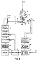
- FIG. 3 represents the block diagram of an exemplary embodiment of the joining device according to the invention. It is intended to be mechanically associated with a target tracking device, so as to have a line of sight LV which is parallel and practically coincident with that of the target tracking device.
- This exemplary embodiment comprises means for projecting and moving an image so as to analyze it by means of a sensor 11.
- the image of the field is scanned circularly by the sensor 11 which consists of an alignment of photosensitive cells, the major axis AC passes through the center of the image.
- the image has the shape of a ring centered on the LV line of sight.
- the presence and the position of the missile are therefore detected by the passage of the image of the missile over at least one of the cells of the sensor 11.
- These means for projecting and moving the image essentially comprise: a lens 12; a movable mirror 13; and a rotating prism, known as Taylor's prism, 14.
- the objective 12 is placed between the sensor 11 and the mirror 13. It forms an image on the sensor 11.
- the mirror 13 is a plane mirror, movable in rotation around an axis AR passing through the plane of the mirror and which is perpendicular both to the optical axis of the objective 12 and to the major axis AC of the alignment of cells constituting the sensor 11.
- the mirror 13 is rotated by a position control device comprising a motor associated with an angular position sensor 16, and comprising a transmission by two pulleys 17 and 18 connected by a belt.
- the axis of rotation and the optical axis of the rotating prism 14 are coincident with the line of sight LV of the rallying device.
- This line of sight LV is parallel to the axis AC and orthogonal to the optical axis of the objective 12.
- the optical axis of the rotating prism 14 and the optical axis of the objective 12 meet on the axis of AR rotation of the mirror.
- the rotating prism 14 has a constant speed of rotation and is driven by a motor 15.
- a light ray 20 captured in the field of the rallying device is deflected by the mirror 13 in a plane containing the line of sight LV and containing the major axis AC of the sensor 11.
- the angular position of the mirror 13 determines the opening of the field of rallying, that is to say the diameter of its section.
- the rotating prism 14 causes the beam 20 to rotate about an axis of rotation coincident with the line of sight LV.
- the rotation movement of the prism 14, for a given position of the mirror 13 causes the circular scrolling of an image on the sensor 11.
- the latter therefore analyzes a ring of this image, the diameter of which is determined by the angular position of the mirror 13.
- the sensor 11 simultaneously analyzes 12 pixels located on a ray of the image.
- the angular position of the mirror 13 varies over time, as a function of the angular difference between the line of sight LV and the direction DM where the missile is located at the instant considered.
- This direction DM is known by determining the position of the missile in the image analyzed by the sensor 11.
- This exemplary embodiment also comprises twelve preamplifiers 21 having inputs connected respectively to the twelve photosensitive cells of the sensor 11, and having twelve outputs connected respectively to the inputs of twelve switchable filters 22.
- the characteristics of these filters are modified, during the flight missile, so that they have a wide bandwidth at the start of the flight, when the missile is easily visible but moves quickly from one pixel to another; and so that they have a reduced bandwidth during the flight, and in particular at the end of the flight, when it is necessary to increase the sensitivity of the joining device by eliminating the noise produced by the sensor 11. During the end of flight the wide bandwidth is no longer necessary because the missile image moves slowly from one pixel to another.
- each of the twelve filters 22 is connected respectively to an input of a multiplexer 23 with twelve inputs and to an output.
- the latter is connected to the input of an analog-digital converter 24.
- the multiplexer 23 is controlled to sequentially select the signals corresponding to the twelve photosensitive cells of the sensor 11.
- the converter 24 has an output connected to a data input of a memory 25, where the values of the twelve signals supplied by the twelve photosensitive cells are stored.
- a processor 26 is connected, by buses, to memory 25 to control the reading and writing of the values of these signals.
- the processor 26 also has control outputs connected respectively to filter control inputs switchable 22 to control their bandwidth during the flight of the missile; and an output connected to a control input of the multiplexer 23 for selecting samples of each of the signals supplied by the twelve photosensitive cells, after amplification by the preamplifiers 21 and filtering by the filters 22.
- the processor 26 has an output connected to an input of a device 27 for calculating the difference between the line of sight LV and the direction DM is located the missile.
- the processor 26 provides the position of the missile as it is detected in the analyzed image.
- the device 27, which is a conventional deviation measurement device, deduces therefrom the coordinates to be supplied to a remote control device or to a device emitting a steering beam, in order to bring the missile in the direction of the line of sight.
- the calculation device 27 has an output connected to an output terminal 30 to provide two coordinates reflecting this difference. It also has an output connected to an input of a missile tracking device 28 which is a conventional device memorizing the speed of the missile to predict the evolution of its trajectory.
- the device 28 has an output connected to an input of a position control device 29 to provide it with a set value reflecting the angular difference between the line of sight and the direction where the missile is located, with a certain anticipation .
- the device 29 has an output connected to the servo motor 16 and an input connected to the position sensor associated with the motor 16. The device 29 controls the motor 16 so that it takes the position corresponding to the set value. The transmission by the pulleys 17 and 18 and their belt, multiplies the precision of the position control of the mirror.
- the device 29 is a conventional position control. Programming the microprocessor 26 to perform the functions described above is within the reach of ordinary skill in the art.
- the field envelope cone has an angular half-opening of 5 °, and if the width of the ring corresponds to an angular opening of 1 °, it is shown that the solid angle of the field is reduced in an equal ratio to 3 with respect to a field having a square section of width corresponding to an angular opening 10 °. And this reduction reaches a ratio of 30 when the missile is rallied on the line of sight.
- the number of photosensitive cells can therefore be reduced compared to a conventional device, or else the performance can be increased if the number of cells is maintained.
- Electronic processing, in particular to eliminate false alarms, is also considerably simplified. It should be noted that the scanning mode used has no dead time, therefore the scanning has a yield of 100% for the analysis of the image. Finally, the probability of the presence of the sun or the presence of a decoy in the field analyzed is reduced in the same proportion.
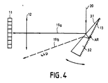
- FIG. 4 represents an alternative embodiment of the mirror 13, comprising a transparent prism 32 which carries, on a first face, a dichroic layer 31 carrying out close filtering.
- a second face of the prism 32 is glued to the surface of the mirror 13.
- the dichroic surface 31 reflects all of the light except for a very narrow band around the wavelength of 4.4 microns, in the case of a joining device working in the band from 3 to 5 microns.
- An incident light ray 20 is deflected along a ray 19a and a ray 19b, making two different angles with respect to the incident ray 20.
- the ray 19a which is reflected by the dichroic surface 31, comprises almost the entire wavelengths , while the ray 19b comprises only the length of 4.4 microns because it has crossed the dichroic surface 31, is reflected on the metallized surface of the mirror 13 and then has crossed again the dichroic surface 31.
- the ray 19b crosses twice the dichroic surface 31 which doubles the efficiency of filtering by this dichroic surface 31, and therefore makes it possible to simplify its production.
- the angle of the prism 32 determines the angular difference between the radii 19a and 19b.
- the position of the mirror 13 is controlled to deflect towards the objective 12 the rays reflected by dichroic surface 31, such as the ray 19a; and deflecting rays such as ray 19b out of objective 12.
- the energy loss is low because the band of wavelengths which crosses the dichroic surface 31 is narrow.
- processor 26 There is an output of the processor 26 connected to an additional input of the position control device 29, to provide it with a control signal in the event that the processor 26 detects false alarms due to the presence of the sun or to the presence of decoy, in order to control the realization of filtering in the vicinity of 4.4 microns.
- the device 29 for position control is controlled by the processor 26, via the devices 27 and 28, to offset the mirror 13 by a predetermined angle equal to the angle of the prism 32.
- the dichroic surface 31 comes in place of the surface of the mirror 13, so as to deflect the ray 19b in the direction of the objective 12 and to deflect the radius 19a out of objective 12.
- the analyzed image comprising only lengths wave near 4.4 microns, it has little energy from the sun or decoys.
Landscapes
- Physics & Mathematics (AREA)
- Engineering & Computer Science (AREA)
- General Physics & Mathematics (AREA)
- Electromagnetism (AREA)
- Radar, Positioning & Navigation (AREA)
- Remote Sensing (AREA)
- Chemical & Material Sciences (AREA)
- Combustion & Propulsion (AREA)
- General Engineering & Computer Science (AREA)
- Optics & Photonics (AREA)
- Aiming, Guidance, Guns With A Light Source, Armor, Camouflage, And Targets (AREA)
Applications Claiming Priority (2)
| Application Number | Priority Date | Filing Date | Title |
|---|---|---|---|
| FR8906718A FR2647540B1 (fr) | 1989-05-23 | 1989-05-23 | Dispositif de ralliement de missile |
| FR8906718 | 1989-05-23 |
Publications (2)
| Publication Number | Publication Date |
|---|---|
| EP0399862A1 true EP0399862A1 (de) | 1990-11-28 |
| EP0399862B1 EP0399862B1 (de) | 1994-03-09 |
Family
ID=9381916
Family Applications (1)
| Application Number | Title | Priority Date | Filing Date |
|---|---|---|---|
| EP90401201A Expired - Lifetime EP0399862B1 (de) | 1989-05-23 | 1990-05-04 | Vorrichtung zur Raketensteuerung |
Country Status (4)
| Country | Link |
|---|---|
| US (1) | US5082201A (de) |
| EP (1) | EP0399862B1 (de) |
| DE (1) | DE69007167D1 (de) |
| FR (1) | FR2647540B1 (de) |
Cited By (1)
| Publication number | Priority date | Publication date | Assignee | Title |
|---|---|---|---|---|
| EP0713076A1 (de) * | 1994-11-15 | 1996-05-22 | Hughes Aircraft Company | Fehlererkennungsgerät mit digitaler Koordinatentransformation |
Families Citing this family (23)
| Publication number | Priority date | Publication date | Assignee | Title |
|---|---|---|---|---|
| US5226614A (en) * | 1992-03-23 | 1993-07-13 | Hughes Aircraft Company | Infrared tracker for a portable missile launcher |
| US5669581A (en) * | 1994-04-11 | 1997-09-23 | Aerojet-General Corporation | Spin-stabilized guided projectile |
| US5695152A (en) * | 1996-09-18 | 1997-12-09 | Israel Aircraft Industries Ltd. | System for correcting flight trajectory of a projectile |
| US5917442A (en) * | 1998-01-22 | 1999-06-29 | Raytheon Company | Missile guidance system |
| US6163372A (en) * | 1999-02-09 | 2000-12-19 | Marconi Aerospace Defense Systems Inc. | Fiber optic laser detection and ranging system |
| US6817569B1 (en) | 1999-07-21 | 2004-11-16 | General Dynamics Ordnance And Tactical Systems, Inc. | Guidance seeker system with optically triggered diverter elements |
| RU2188381C2 (ru) * | 2000-02-14 | 2002-08-27 | Государственное унитарное предприятие "Конструкторское бюро приборостроения" | Способ командного телеуправления ракетой |
| RU2192603C2 (ru) * | 2000-07-04 | 2002-11-10 | Общевойсковая Академия Вооруженных Сил Российской Федерации | Способ наведения управляемой ракеты |
| RU2192605C2 (ru) * | 2000-09-26 | 2002-11-10 | Государственное унитарное предприятие "Конструкторское бюро приборостроения" | Способ наведения телеуправляемой ракеты и система наведения для его реализации |
| US6507392B1 (en) | 2001-04-16 | 2003-01-14 | Bae Systems Information And Electronic Systems Integration Inc. | Single multiple aperture (“SMART”) lens system |
| US6943873B2 (en) | 2001-07-17 | 2005-09-13 | Bae Systems Integrated Defense Solutions Inc. | Fiber optical laser detection and ranging system |
| RU2213318C1 (ru) * | 2002-05-13 | 2003-09-27 | Общевойсковая Академия Вооруженных Сил Российской Федерации | Способ наведения управляемой ракеты |
| RU2213926C1 (ru) * | 2002-05-29 | 2003-10-10 | Общевойсковая Академия Вооруженных Сил Российской Федерации | Способ наведения управляемой ракеты |
| RU2234661C1 (ru) * | 2002-11-26 | 2004-08-20 | Государственное унитарное предприятие "Конструкторское бюро приборостроения" | Оптический прицел системы наведения управляемого снаряда |
| RU2241195C1 (ru) * | 2003-06-03 | 2004-11-27 | Государственное унитарное предприятие "Конструкторское бюро приборостроения" | Способ наведения управляемой ракеты и система наведения для его реализации |
| JP4285367B2 (ja) * | 2003-10-29 | 2009-06-24 | セイコーエプソン株式会社 | 視線誘導度算出システムおよび視線誘導度算出プログラム、並びに視線誘導度算出方法 |
| GB0401389D0 (en) * | 2004-01-22 | 2004-02-25 | Remtons Ltd | Illumination method and apparatus |
| US7219853B2 (en) * | 2004-06-21 | 2007-05-22 | Raytheon Company | Systems and methods for tracking targets with aimpoint offset |
| RU2334936C1 (ru) * | 2007-02-20 | 2008-09-27 | Общевойсковая Академия Вооруженных Сил Российской Федерации (Оа Вс Рф) | Способ наведения управляемой ракеты |
| US20090079837A1 (en) * | 2007-09-24 | 2009-03-26 | Honeywell International Inc. | Image stabilization for image based navigation system |
| US8872081B2 (en) * | 2011-11-01 | 2014-10-28 | Ge Aviation Systems Llc | Methods for adjusting a relative navigation system |
| US9435635B1 (en) | 2015-02-27 | 2016-09-06 | Ge Aviation Systems Llc | System and methods of detecting an intruding object in a relative navigation system |
| RU2751433C1 (ru) * | 2020-12-15 | 2021-07-13 | Общество с ограниченной ответственностью "Опытно-конструкторское бюро УЗГА" (ООО "ОКБ УЗГА") | Способ целеуказания по направлению системе наведения управляемого объекта |
Citations (8)
| Publication number | Priority date | Publication date | Assignee | Title |
|---|---|---|---|---|
| FR2312760A1 (fr) * | 1975-05-30 | 1976-12-24 | Bofors Ab | Systeme de determination de l'ecart d'un objet par rapport a une ligne de reference |
| US4193688A (en) * | 1970-10-28 | 1980-03-18 | Raytheon Company | Optical scanning system |
| US4236177A (en) * | 1978-01-17 | 1980-11-25 | Canon Kabushiki Kaisha | Beam splitting prism assembly with bias light source |
| GB2071957A (en) * | 1980-02-14 | 1981-09-23 | Messerschmitt Boelkow Blohm | Panoramic locating apparatus |
| GB2087185A (en) * | 1980-11-03 | 1982-05-19 | Philips Nv | Missile guidance using hot point detection |
| EP0099769A1 (de) * | 1982-06-18 | 1984-02-01 | Thomson-Csf | Vorrichtung zur Analyse eines räumlichen Feldes zur Winkelortung eines strahlenden Objektes |
| GB2184313A (en) * | 1982-04-26 | 1987-06-17 | Trt Telecom Radio Electr | Infra-red sensing and missile guidance |
| US4773754A (en) * | 1981-11-30 | 1988-09-27 | Ford Motor Company | End-point optical tracker |
Family Cites Families (22)
| Publication number | Priority date | Publication date | Assignee | Title |
|---|---|---|---|---|
| US3912859A (en) * | 1962-06-08 | 1975-10-14 | Philco Ford Corp | Electronic tracking device |
| US4227077A (en) * | 1973-02-26 | 1980-10-07 | Raytheon Company | Optical tracking system utilizing spaced-apart detector elements |
| US4383663A (en) * | 1976-06-01 | 1983-05-17 | The United States Of America As Represented By The Secretary Of The Navy | Active optical terminal homing |
| US4243187A (en) * | 1978-05-01 | 1981-01-06 | Mcdonnell Douglas Corporation | Missile director with beam axis shift capability |
| FR2478309A1 (fr) * | 1980-03-13 | 1981-09-18 | Exxon France | Appareil de mesure des viscosites et de la densite de fluides |
| FR2492616A1 (fr) * | 1980-10-17 | 1982-04-23 | Thomson Csf | Dispositif opto-electronique d'analyse d'images video-frequence par balayage rotatif |
| FR2502875B1 (fr) * | 1981-03-30 | 1985-11-29 | Tugaye Jean | Procede et dispositif de cadrage et de stabilisation d'image de camera electro-optique |
| FR2517818A1 (fr) * | 1981-12-09 | 1983-06-10 | Thomson Brandt | Methode de guidage terminal et missile guide operant selon cette methode |
| JPS58106249A (ja) * | 1981-12-19 | 1983-06-24 | Honda Motor Co Ltd | 可変容量フライホイ−ル |
| US4537370A (en) * | 1983-11-02 | 1985-08-27 | Ford Aerospace & Communications Corporation | Optical growth compensator |
| DE3343259A1 (de) * | 1983-11-30 | 1985-06-05 | Diehl GmbH & Co, 8500 Nürnberg | Verfahren zum vergroessern der effektivitaet zielsuchender munitionsartikel |
| FR2564597B1 (fr) * | 1984-05-17 | 1986-09-19 | Telecommunications Sa | Dispositif de determination de l'ecartometrie d'un missile |
| DE3441921A1 (de) * | 1984-11-16 | 1986-05-28 | Messerschmitt-Bölkow-Blohm GmbH, 8012 Ottobrunn | Leitstrahl- und nachfuehreinrichtung |
| US4615496A (en) * | 1985-01-03 | 1986-10-07 | The Boeing Company | Hybrid semi-strapdown infrared seeker |
| FR2583523B1 (fr) * | 1985-06-17 | 1988-07-15 | Aerospatiale | Systeme pour la localisation d'un mobile. |
| US4728057A (en) * | 1985-11-22 | 1988-03-01 | Ship Systems, Inc. | Spin-stabilized projectile with pulse receiver and method of use |
| DE3602456A1 (de) * | 1986-01-28 | 1987-07-30 | Diehl Gmbh & Co | Zielverfolgungseinrichtung |
| DE3615266A1 (de) * | 1986-05-06 | 1987-11-12 | Diehl Gmbh & Co | Abstandszuendeinrichtung |
| US4712270A (en) * | 1987-02-02 | 1987-12-15 | Hako Minuteman, Inc. | Brake drum encapsulator |
| US4965453A (en) * | 1987-09-17 | 1990-10-23 | Honeywell, Inc. | Multiple aperture ir sensor |
| FR2627268B1 (fr) * | 1988-02-12 | 1993-05-14 | Thomson Brandt Armements | Systeme de guidage de vecteur par faisceau laser et impulseurs pyrotechniques, et vecteur guide par un tel systeme |
| US4770482A (en) * | 1988-07-17 | 1988-09-13 | Gte Government Systems Corporation | Scanning system for optical transmitter beams |
-
1989
- 1989-05-23 FR FR8906718A patent/FR2647540B1/fr not_active Expired - Fee Related
-
1990
- 1990-05-04 EP EP90401201A patent/EP0399862B1/de not_active Expired - Lifetime
- 1990-05-04 DE DE90401201T patent/DE69007167D1/de not_active Expired - Lifetime
- 1990-05-11 US US07/522,040 patent/US5082201A/en not_active Expired - Fee Related
Patent Citations (8)
| Publication number | Priority date | Publication date | Assignee | Title |
|---|---|---|---|---|
| US4193688A (en) * | 1970-10-28 | 1980-03-18 | Raytheon Company | Optical scanning system |
| FR2312760A1 (fr) * | 1975-05-30 | 1976-12-24 | Bofors Ab | Systeme de determination de l'ecart d'un objet par rapport a une ligne de reference |
| US4236177A (en) * | 1978-01-17 | 1980-11-25 | Canon Kabushiki Kaisha | Beam splitting prism assembly with bias light source |
| GB2071957A (en) * | 1980-02-14 | 1981-09-23 | Messerschmitt Boelkow Blohm | Panoramic locating apparatus |
| GB2087185A (en) * | 1980-11-03 | 1982-05-19 | Philips Nv | Missile guidance using hot point detection |
| US4773754A (en) * | 1981-11-30 | 1988-09-27 | Ford Motor Company | End-point optical tracker |
| GB2184313A (en) * | 1982-04-26 | 1987-06-17 | Trt Telecom Radio Electr | Infra-red sensing and missile guidance |
| EP0099769A1 (de) * | 1982-06-18 | 1984-02-01 | Thomson-Csf | Vorrichtung zur Analyse eines räumlichen Feldes zur Winkelortung eines strahlenden Objektes |
Cited By (2)
| Publication number | Priority date | Publication date | Assignee | Title |
|---|---|---|---|---|
| EP0713076A1 (de) * | 1994-11-15 | 1996-05-22 | Hughes Aircraft Company | Fehlererkennungsgerät mit digitaler Koordinatentransformation |
| US5799899A (en) * | 1994-11-15 | 1998-09-01 | Hughes Electronics | Error detector apparatus with digital coordinate transformation |
Also Published As
| Publication number | Publication date |
|---|---|
| US5082201A (en) | 1992-01-21 |
| EP0399862B1 (de) | 1994-03-09 |
| FR2647540B1 (fr) | 1994-03-25 |
| FR2647540A1 (fr) | 1990-11-30 |
| DE69007167D1 (de) | 1994-04-14 |
Similar Documents
| Publication | Publication Date | Title |
|---|---|---|
| EP0399862B1 (de) | Vorrichtung zur Raketensteuerung | |
| EP0004227B1 (de) | Einrichtung zur optoelektrischen Detektion und zur Bestimmung der Winkelablage eines leuchtenden Objekts, sowie deren Verwendung | |
| EP0033679A1 (de) | System zur Andeutung eines Objektes mittels eines Lasers | |
| EP0241374B1 (de) | Optronische Abweichungsvorrichtung zur räumlichen und spektralen Erkennung von infraroten Lichtquellen | |
| EP0568426B1 (de) | Verfahren und Einrichtung zur Entdeckung und Ortung von Objekten auf einem relativ ebenen Boden | |
| EP2173042B1 (de) | Optische Sende-Empfangseinheit mit Kontrolle der Senderichtung | |
| FR2669108A1 (fr) | Dispositif optique de mesure de l'angle de roulis d'un projectile. | |
| FR2476325A1 (fr) | Systeme de reperage omnidirectionnel pour objets en mouvement | |
| FR2729764A1 (fr) | Radar a champ angulaire instantane important et haut pouvoir instantane de resolution angulaire, notamment pour autodirecteur de missile | |
| FR2661738A1 (fr) | Procede pour la detection et la poursuite d'un but, notamment d'un engin volant. | |
| WO1993025927A9 (fr) | Dispositif de veille panoramique infrarouge a grande portee | |
| EP0432025B1 (de) | Optisches Nachrichtenübertragungssystem | |
| EP0012060A1 (de) | Anordnung zur optoelektrischen Detektion und Winkelortung eines leuchtenden Gegenstandes | |
| EP0405678A1 (de) | Erd-Horizontsensor mit verbesserter Genauigkeit | |
| EP0702246A1 (de) | Tragbares Gerät zum Messen der Rückstreuung von Licht | |
| FR2764710A1 (fr) | Dispositif de visee stabilisee multispectral | |
| EP0493256B1 (de) | Näherungsdetektor und Verfahren zur sektoriellen Zielerfassung als Zünder für einen Sprengkörper | |
| FR1464783A (fr) | Perfectionnements aux systèmes de détection de radiations infrarouges | |
| FR2687791A1 (fr) | Systeme optronique de poursuite tridimensionnelle avec alignement automatique d'un telemetre optique sur la cible. | |
| FR2655140A1 (fr) | Systeme a fusee declenchee a distance. | |
| FR2533883A1 (fr) | Senseur d'horizon terrestre utilisant des photodetecteurs a transfert de charges | |
| FR2551890A1 (fr) | Dispositif d'analyse de champ spatial pour la localisation angulaire d'objets rayonnants | |
| FR2481794A1 (fr) | Dispositif optique d'analyse d'un champ spatial et de localisation angulaire d'un objet rayonnant dans ce champ | |
| EP0169128B1 (de) | Optoelektrische Vorrichtung zur Richtungsentdeckung und -ortung von Lichtquellen mit hohem Schutz gegenüber Gegenmassnahmen | |
| EP1202021B1 (de) | Vorrichtung zur Justierung eines Lasersendungskanals mit einem passiven Beobachtungskanal |
Legal Events
| Date | Code | Title | Description |
|---|---|---|---|
| PUAI | Public reference made under article 153(3) epc to a published international application that has entered the european phase |
Free format text: ORIGINAL CODE: 0009012 |
|
| AK | Designated contracting states |
Kind code of ref document: A1 Designated state(s): DE GB IT NL |
|
| 17P | Request for examination filed |
Effective date: 19910405 |
|
| 17Q | First examination report despatched |
Effective date: 19930714 |
|
| GRAA | (expected) grant |
Free format text: ORIGINAL CODE: 0009210 |
|
| RAP1 | Party data changed (applicant data changed or rights of an application transferred) |
Owner name: THOMSON-CSF |
|
| AK | Designated contracting states |
Kind code of ref document: B1 Designated state(s): DE GB IT NL |
|
| PG25 | Lapsed in a contracting state [announced via postgrant information from national office to epo] |
Ref country code: IT Free format text: LAPSE BECAUSE OF FAILURE TO SUBMIT A TRANSLATION OF THE DESCRIPTION OR TO PAY THE FEE WITHIN THE PRESCRIBED TIME-LIMIT;WARNING: LAPSES OF ITALIAN PATENTS WITH EFFECTIVE DATE BEFORE 2007 MAY HAVE OCCURRED AT ANY TIME BEFORE 2007. THE CORRECT EFFECTIVE DATE MAY BE DIFFERENT FROM THE ONE RECORDED. Effective date: 19940309 Ref country code: DE Effective date: 19940309 Ref country code: GB Effective date: 19940309 |
|
| REF | Corresponds to: |
Ref document number: 69007167 Country of ref document: DE Date of ref document: 19940414 |
|
| GBV | Gb: ep patent (uk) treated as always having been void in accordance with gb section 77(7)/1977 [no translation filed] |
Effective date: 19940309 |
|
| PG25 | Lapsed in a contracting state [announced via postgrant information from national office to epo] |
Ref country code: NL Effective date: 19941201 |
|
| PLBE | No opposition filed within time limit |
Free format text: ORIGINAL CODE: 0009261 |
|
| STAA | Information on the status of an ep patent application or granted ep patent |
Free format text: STATUS: NO OPPOSITION FILED WITHIN TIME LIMIT |
|
| NLV4 | Nl: lapsed or anulled due to non-payment of the annual fee | ||
| 26N | No opposition filed |