EP0398046B1 - Verfahren zur Herstellung eines flexiblen keramischen Elements sowie flexibles keramisches Element - Google Patents
Verfahren zur Herstellung eines flexiblen keramischen Elements sowie flexibles keramisches Element Download PDFInfo
- Publication number
- EP0398046B1 EP0398046B1 EP90107809A EP90107809A EP0398046B1 EP 0398046 B1 EP0398046 B1 EP 0398046B1 EP 90107809 A EP90107809 A EP 90107809A EP 90107809 A EP90107809 A EP 90107809A EP 0398046 B1 EP0398046 B1 EP 0398046B1
- Authority
- EP
- European Patent Office
- Prior art keywords
- tube
- grooves
- ceramic material
- elasticity
- component
- Prior art date
- Legal status (The legal status is an assumption and is not a legal conclusion. Google has not performed a legal analysis and makes no representation as to the accuracy of the status listed.)
- Expired - Lifetime
Links
Images
Classifications
-
- F—MECHANICAL ENGINEERING; LIGHTING; HEATING; WEAPONS; BLASTING
- F16—ENGINEERING ELEMENTS AND UNITS; GENERAL MEASURES FOR PRODUCING AND MAINTAINING EFFECTIVE FUNCTIONING OF MACHINES OR INSTALLATIONS; THERMAL INSULATION IN GENERAL
- F16F—SPRINGS; SHOCK-ABSORBERS; MEANS FOR DAMPING VIBRATION
- F16F1/00—Springs
- F16F1/02—Springs made of steel or other material having low internal friction; Wound, torsion, leaf, cup, ring or the like springs, the material of the spring not being relevant
- F16F1/021—Springs made of steel or other material having low internal friction; Wound, torsion, leaf, cup, ring or the like springs, the material of the spring not being relevant characterised by their composition, e.g. comprising materials providing for particular spring properties
- F16F1/022—Springs made of steel or other material having low internal friction; Wound, torsion, leaf, cup, ring or the like springs, the material of the spring not being relevant characterised by their composition, e.g. comprising materials providing for particular spring properties made of ceramic materials
-
- B—PERFORMING OPERATIONS; TRANSPORTING
- B28—WORKING CEMENT, CLAY, OR STONE
- B28B—SHAPING CLAY OR OTHER CERAMIC COMPOSITIONS; SHAPING SLAG; SHAPING MIXTURES CONTAINING CEMENTITIOUS MATERIAL, e.g. PLASTER
- B28B1/00—Producing shaped prefabricated articles from the material
-
- B—PERFORMING OPERATIONS; TRANSPORTING
- B28—WORKING CEMENT, CLAY, OR STONE
- B28B—SHAPING CLAY OR OTHER CERAMIC COMPOSITIONS; SHAPING SLAG; SHAPING MIXTURES CONTAINING CEMENTITIOUS MATERIAL, e.g. PLASTER
- B28B11/00—Apparatus or processes for treating or working the shaped or preshaped articles
- B28B11/12—Apparatus or processes for treating or working the shaped or preshaped articles for removing parts of the articles by cutting
-
- F—MECHANICAL ENGINEERING; LIGHTING; HEATING; WEAPONS; BLASTING
- F16—ENGINEERING ELEMENTS AND UNITS; GENERAL MEASURES FOR PRODUCING AND MAINTAINING EFFECTIVE FUNCTIONING OF MACHINES OR INSTALLATIONS; THERMAL INSULATION IN GENERAL
- F16F—SPRINGS; SHOCK-ABSORBERS; MEANS FOR DAMPING VIBRATION
- F16F1/00—Springs
- F16F1/02—Springs made of steel or other material having low internal friction; Wound, torsion, leaf, cup, ring or the like springs, the material of the spring not being relevant
- F16F1/04—Wound springs
-
- Y—GENERAL TAGGING OF NEW TECHNOLOGICAL DEVELOPMENTS; GENERAL TAGGING OF CROSS-SECTIONAL TECHNOLOGIES SPANNING OVER SEVERAL SECTIONS OF THE IPC; TECHNICAL SUBJECTS COVERED BY FORMER USPC CROSS-REFERENCE ART COLLECTIONS [XRACs] AND DIGESTS
- Y10—TECHNICAL SUBJECTS COVERED BY FORMER USPC
- Y10T—TECHNICAL SUBJECTS COVERED BY FORMER US CLASSIFICATION
- Y10T428/00—Stock material or miscellaneous articles
- Y10T428/13—Hollow or container type article [e.g., tube, vase, etc.]
- Y10T428/131—Glass, ceramic, or sintered, fused, fired, or calcined metal oxide or metal carbide containing [e.g., porcelain, brick, cement, etc.]
-
- Y—GENERAL TAGGING OF NEW TECHNOLOGICAL DEVELOPMENTS; GENERAL TAGGING OF CROSS-SECTIONAL TECHNOLOGIES SPANNING OVER SEVERAL SECTIONS OF THE IPC; TECHNICAL SUBJECTS COVERED BY FORMER USPC CROSS-REFERENCE ART COLLECTIONS [XRACs] AND DIGESTS
- Y10—TECHNICAL SUBJECTS COVERED BY FORMER USPC
- Y10T—TECHNICAL SUBJECTS COVERED BY FORMER US CLASSIFICATION
- Y10T428/00—Stock material or miscellaneous articles
- Y10T428/24—Structurally defined web or sheet [e.g., overall dimension, etc.]
- Y10T428/24479—Structurally defined web or sheet [e.g., overall dimension, etc.] including variation in thickness
-
- Y—GENERAL TAGGING OF NEW TECHNOLOGICAL DEVELOPMENTS; GENERAL TAGGING OF CROSS-SECTIONAL TECHNOLOGIES SPANNING OVER SEVERAL SECTIONS OF THE IPC; TECHNICAL SUBJECTS COVERED BY FORMER USPC CROSS-REFERENCE ART COLLECTIONS [XRACs] AND DIGESTS
- Y10—TECHNICAL SUBJECTS COVERED BY FORMER USPC
- Y10T—TECHNICAL SUBJECTS COVERED BY FORMER US CLASSIFICATION
- Y10T428/00—Stock material or miscellaneous articles
- Y10T428/24—Structurally defined web or sheet [e.g., overall dimension, etc.]
- Y10T428/24479—Structurally defined web or sheet [e.g., overall dimension, etc.] including variation in thickness
- Y10T428/2457—Parallel ribs and/or grooves
-
- Y—GENERAL TAGGING OF NEW TECHNOLOGICAL DEVELOPMENTS; GENERAL TAGGING OF CROSS-SECTIONAL TECHNOLOGIES SPANNING OVER SEVERAL SECTIONS OF THE IPC; TECHNICAL SUBJECTS COVERED BY FORMER USPC CROSS-REFERENCE ART COLLECTIONS [XRACs] AND DIGESTS
- Y10—TECHNICAL SUBJECTS COVERED BY FORMER USPC
- Y10T—TECHNICAL SUBJECTS COVERED BY FORMER US CLASSIFICATION
- Y10T428/00—Stock material or miscellaneous articles
- Y10T428/29—Coated or structually defined flake, particle, cell, strand, strand portion, rod, filament, macroscopic fiber or mass thereof
- Y10T428/2913—Rod, strand, filament or fiber
- Y10T428/2973—Particular cross section
- Y10T428/2978—Surface characteristic
Definitions
- the invention relates to a method for producing a flexible ceramic element according to the preamble of claim 1 and to a flexible, ceramic element according to the preamble of claim 9.
- Such ceramic elements are said to be in an environment of high temperatures, e.g. above 1,000 ° C and / or in corrosive environments.
- a sintered zirconium oxide material and a method for its production are known from US Pat. No. 4,742,030. It is said to be used, for example, to manufacture a spring or a coil spring and to have a modulus of elasticity of 200,000 MPa and a bending strength of 1,000 MPa. A method for the production of flexible ceramic elements is not specified.
- EP-A 0 220 769 discloses a method for producing a cylindrical spring for use at high temperatures.
- the spring should consist of quartz, boron nitride or graphite and, for example, of a cylindrical tube, which is arranged with recesses spaced apart from one another using a saw is provided.
- the proposed materials are only suitable to a very limited extent for the production of such a spring, either in terms of the desired temperature resistance and corrosion resistance, or in terms of the flexibility that can be achieved.
- the element which is formed from ceramic material according to the invention can be given the desired degree of flexibility in a simple manner.
- an element such as a spring, bellows or flexible shaft, with a different degree of flexibility, which is necessary for different applications, while at the same time ensuring that the flexible element withstands a high temperature environment and / or a corrosive atmosphere or corrosive media.
- the flexible element can be exposed to high temperatures, for example above 1000 ° C., and corrosive atmospheres or media without damage or deformation.
- the element can be given the desired degree of flexibility and elasticity, which is necessary for the use of such an element, and yet the stress caused by high temperatures and / or corrosive media is harmless.
- the ceramic material is used to first form a tubular component, such a molded part preferably being completely fired.
- the component is then provided with a plurality of circumferential grooves in order to create a desired degree of flexibility or flexibility.
- the grooves can e.g. by means of cutting, sawing or milling etc. in the shaped tubular component.
- the grooves can give the tubular component the final shape depending on the degree and direction or type of flexibility and / or elasticity required.
- the ceramic materials used can be selected depending on the intended application of the element.
- the starting component for the element shown in the drawings is a fully fired molded part made of ceramic material, for example oxide-ceramic material, and in particular partially or fully stabilized zirconium oxide.
- the ceramic material has a modulus of elasticity of 150,000 to 200,000 MPa, preferably 170,000 to 180,000 MPa.
- the flexural strength of the fully fired ceramic material is greater than 400 MPa, preferably 1,000 to 1,400 MPa.
- the molded component is provided with sections of reduced thickness, which will be described in more detail below.
- sections of reduced thickness can be produced using various mechanical processes, such as cutting, sawing or milling. The location, size and number of sections of reduced thickness are selected according to the desired degree of flexibility and / or elasticity to be realized in the particular element.
- a preferred ceramic material is a partially or fully stabilized zirconium oxide (ZrO2).
- ZrO2 partially or fully stabilized zirconium oxide
- By stabilizing the zirconium oxide it is possible to reduce the brittleness or shrinkage at temperatures above 1,000 ° C.
- To stabilize the zirconium oxide it is possible to use magnesium, calcium or in particular yttrium, or mixtures thereof, the quantity of the additive generally being below about 1 to 3% by weight.
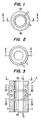
- FIGS. 1 to 3 show the configuration of a flexible element 4, which is designed as a bellows from a tubular component 3.
- circumferential grooves 5 and 6 are alternately formed.
- the grooves 5, 6 extend only through a section of the thickness of the tubular component 3.
- the grooves 5, 6 alternate in the direction of the longitudinal axis L of the element 4.
- the grooves 5, 6 are dimensioned and arranged such that the remaining part of the tubular Component 3 forms the element 4 with a desired degree of flexibility and elasticity in the direction of arrow D and a desired degree of resilience and elasticity in the direction of arrow S, as well as a desired degree of flexibility in direction B perpendicular to the longitudinal axis L. .
- Element 4 of FIGS. 1 to 3 is suitable for the transmission of torsional forces. Furthermore, it is not necessary for the circumferential grooves 5, 6 to be provided along the entire longitudinal extent of the tubular component 3. It is possible to provide suitably dimensioned end sections or segments which are free of such cuts of reduced thickness, e.g. to clamp the components in or on other elements, such as holders or supports.
Landscapes
- Engineering & Computer Science (AREA)
- General Engineering & Computer Science (AREA)
- Mechanical Engineering (AREA)
- Chemical & Material Sciences (AREA)
- Ceramic Engineering (AREA)
- Manufacturing & Machinery (AREA)
- Structural Engineering (AREA)
- Compositions Of Oxide Ceramics (AREA)
- Springs (AREA)
- Apparatuses And Processes For Manufacturing Resistors (AREA)
- Ceramic Capacitors (AREA)
Description
- Die Erfindung bezieht sich auf ein Verfahren zur Herstellung eines flexiblen keramischen Elements nach dem Oberbegriff des Anspruchs 1 sowie auf ein flexibles, keramisches Element nach dem Oberbegriff des Anspruchs 9.
- Solche keramischen Element sollen in einer Umgebung hoher Temperaturen, von z.B. über 1.000 °C und/oder in korrosiver Umgebung benutzbar sein.
- Wenn flexible Elemente, wie Federn, Bälge oder flexible Wellen eingesetzt werden mußten, war es bisher notwendig, diese aus Metall zu bilden, um die notwendigen Eigenschaften von Flexibilität und Elastizität zur Verfügung zu stellen. Solche Elemente aus Metall sind jedoch für den Einsatz in einer Hochtemperaturumgebung und/oder in einer korrosiven Atmosphäre oder in korrosiven Medien nicht sehr geeignet, da Metalle solchen Umgebungen oder Atmosphären nicht ohne weiteres standhalten und unter solchen Bedingungen einem wesentlichen Verschleiß ausgesetzt sind.
- Aus der US-A 4 742 030 ist ein gesintertes Zirkonoxid-Material und ein Verfahren zu dessen Herstellung bekannt. Es soll beispielsweise zur Herstellung einer Feder oder einer Schraubenfeder verwendet werden und einen Elastizitätsmodul von 200.000 MPa und eine Biegefestigkeit von 1.000 MPa haben können. Ein Verfahren zur Herstellung von flexiblen keramischen Elementen ist darin nicht angegeben.
- Aus der EP-A 0 220 769 ist ein Verfahren zur Herstellung einer zylindrischen Feder für die Anwendung bei hohen Temperaturen bekannt. Die Feder soll aus Quarz, Bornitrid oder Graphit bestehen und z.B. aus einem zylindrischen Rohr, das mit im Abstand voneinander angeordneten Aussparungen mit einer Säge versehen wird, hergestellt werden. Die vorgeschlagenen Materialien eignen sich jedoch nur in sehr beschränktem Maße für die Herstellung einer solchen Feder, sei es, was die gewünschte Temperaturwiderstandsfähigkeit und Korrosionsbeständigkeit, sei es, was die erzielbare Flexibilität anbelangt.
- Aus der JP-A 62-160 743 ist ein Verfahren zur Herstellung einer keramischen Spiralfeder bekannt. Um eine Verformung der Feder vor dem Brennen zu verhindern, sind die Windungen der Spiralfeder zunächst durch dünne Verbindungsstücke fixiert, die nach dem Brennen weggeschliffen werden.
- Hiervon ausgehend ist es Aufgabe der Erfindung, ein Verfahren zur Herstellung eines flexiblen Elements und ein flexibles Element zur Verfügung zu stellen, welches einer Hochtemperaturumgebung oder einer korrosiven Atmosphäre oder korrosiven Medien besser standhält und dessen Flexibilität besser an die gegebenen Verhältnisse anpaßbar ist.
- Diese Aufgabe wird erfindungsgemäß mit den Merkmalen des Anspruchs 1 (Verfahren) bzw. den Merkmalen des Anspruchs 9 (Element) gelöst.
- Dem Element, das erfindungsgemäß aus keramischem Material geformt ist, kann auf einfache Weise jeweils der gewünschte Grad an Flexibilität gegeben werden. Als Ergebnis der besonderen Materialauswahl und Fertigungsmethode ist es möglich, eine Element, wie eine Feder, einen Balg oder eine flexible Welle, mit einem unterschiedlichen Grad an Flexibilität zu bilden, der für verschiedene Anwendungen notwendig ist, während zugleich gewährleistet wird, daß das flexible Element einer Hochtemperaturumgebung und/oder einer korrosiven Atmosphäre oder korrosiven Medien standhält. Auf diese Weise kann das flexible Element hohen Temperaturen, beispielsweise über 1.000°C, und korrosiven Atmosphären oder Medien ohne Schädigung oder Verformung ausgesetzt werden. Es ist überraschend, daß trotz des verwendeten keramischen Materials und trotz der angewendeten Herstellungsweise gemäß der Erfindung dem Element der jeweils gewünschte Grad an Flexibilität und Elastizität gegeben werden kann, der zum Gebrauch von einem solchen Element notwendig ist, und daß dennoch die Beanspruchung durch hohe Temperaturen und/oder korrosive Medien unschädlich ist.
- Das keramische Material wird eingesetzt, um zunächst ein rohrförmiges Bauteil zu formen, wobei solch ein geformtes Teil vorzugsweise vollständig gebrannt ist. Das Bauteil wird dann mit einer Vielzahl von umlaufenden Nuten versehen, um einen gewünschten Grad an Biegsamkeit oder Flexibilität zu schaffen. Die Nuten können z.B. mittels Schneiden, Sägen oder Fräsen etc. in dem geformten rohrförmigen Bauteil angebracht werden.
- Die Nuten können dem rohrförmigen Bauteil in Abhängigkeit von dem benötigten Grad und der benötigten Richtung oder Art an Flexibilität und/oder Elastizität die endgültige Gestalt geben. Die eingesetzten keramischen Materialien können in Abhängigkeit von der beabsichtigten Anwendung des Elements ausgewählt werden.
- Weitere Einzelheiten der Erfindung werden nachfolgend anhand der Zeichnung näher erläutert.
- Es zeigen:
- Figur 1
- einen Querschnitt gemäß Linie III-III in Figur 3 eines Balges, der aus einem rohrförmigen, aus keramischem Material geformten Bauteil gebildet ist;
- Figur 2
- einen ähnlichen Querschnitt, jedoch gemäß Linie IV-IV in Figur 3;
- Figur 3
- einen Längsschnitt gemäß Linie V-V in Figur 1 und Figur 2.
- Das Ausgangsbauteil für das in den Zeichnungen dargestellte Element ist ein vollständig gebranntes geformtes Teil aus keramischem Material, beispielsweise oxid-keramischem Material, und insbesondere teilweise oder vollständig stabilisiertem Zirkonoxid. Das keramische Material weist ein Elastizitätsmodul von 150.000 bis 200.000 MPa, vorzugsweise 170.000 bis 180.000 MPa, auf. Die Biegefestigkeit des vollständig gebrannten keramischen Materials ist größer als 400 MPa, vorzugsweise 1.000 bis 1.400 MPa.
- Um solch ein vollständig gebranntes und geformtes Teil aus solchem keramischen Material mit der gewünschten Flexibilität und/oder Elastizität auszustatten, ist das geformte Bauteil mit Abschnitten verminderter Dicke versehen, welches detaillierter im folgenden beschrieben wird. Solche Abschnitte verminderter Dicke können mit verschiedenen mechanischen Vorgängen, wie Schneiden, Sägen oder Fräsen, hergestellt werden. Die Lage, Größe und Anzahl der Abschnitte verminderter dicke werden entsprechend dem gewünschten Grad der in dem speziellen Element zu verwirklichenden Flexibilität und/oder Elastizität ausgewählt.
- Ein bevorzugtes keramisches Material ist ein teilweise oder vollständig stabilisiertes Zirkonoxid (ZrO₂). Durch Stabilisieren des Zirkonoxids ist es möglich, die Sprödigkeit oder Schrumpfung bei Temperaturen über 1.000°C zu vermindern. Zur Stabilisierung des Zirkonoxids ist es möglich, Magnesium, Kalzium oder insbesondere Yttrium, oder Mischungen davon zu verwenden, wobei die Quantität des Zusatzes im allgemeinen unter etwa 1 bis 3 Gew.-% liegt.
- Die Figuren 1 bis 3 zeigen die Ausgestaltung eines flexiblen, als Balg aus einem rohrförmig geformten Bauteil 3 ausgebildeten Elements 4. In den inneren und den äußeren Oberflächen des rohrförmigen Bauteils 3 sind abwechselnd umlaufende Nuten 5 bzw. 6 ausgebildet. Die Nuten 5, 6 erstrecken sich lediglich durch einen Abschnitt der Dicke des rohrförmigen Bauteils 3. Die Nuten 5, 6 wechseln sich in der Richtung der Längsachse L des Elements 4 ab. Die Nuten 5, 6 sind derart dimensioniert und angeordnet, daß der verbleibende Teil des rohrförmigen Bauteils 3 das Element 4 mit einem gewünschten Grad an Flexibilität und Elastizität in der Richtung des Pfeils D und einem gewünschten Grad an Nachgiebigkeit und Elastizität in der Richtung des Pfeils S, sowie einen gewünschten Grad an Flexibilität in der Richtung B senkrecht zu der Längsachse L bildet.
- Das Element 4 der Figuren 1 bis 3 ist zur Übertragung von Torsionskräften geeignet. Darüberhinaus ist es nicht notwendig, daß die umlaufenden Nuten 5, 6 entlang der gesamten Längserstreckung des rohrförmigen Bauteils 3 vorgesehen sind. Es ist möglich, geeignet dimensionierte Endabschnitte oder Segmente vorzusehen, die frei von solchen Aschnitten verminderter Dicke sind, z.B. um die Bauteile in oder auf andere Element , wie Halter oder Träger, zu klemmen.
Claims (16)
- Verfahren zur Herstellung eines flexiblen keramischen Elements, welches hochtemperaturbeständig ist und/oder korrosiven Atmosphären oder Medien standhält,
dadurch gekennzeichnet,
daß man ein Bauteil in Gestalt eines Rohres (3) aus einem keramischen Material mit einem Elastizitätsmodul von 150.000 bis 200.000 MPa und einer Biegefestigkeit von mehr als 400 MPa hergestellt, und an diesem Bauteil für den gewünschten Grad an Flexibilität Abschnitte verminderter Dicke in Form einer Vielzahl von umlaufenden Nuten (5, 6), die sich lediglich über einen Teil der Dicke der Wand des Rohres (3) erstrecken, anbringt. - Verfahren nach Anspruch 1,
dadurch gekennzeichnet,
daß der Elastizitätsmodul zwischen 170.000 und 180.000 MPa liegt. - Verfahren nach Anspruch 1 oder 2,
dadurch gekennzeichnet,
daß die Biegefestigkeit zwischen 1.000 und 1.400 MPa liegt. - Verfahren nach einem der Ansprüche 1 bis 3,
dadurch gekennzeichnet.
daß man als keramisches Material ein oxid-keramisches Material, wie teilweise oder vollständig stabilisiertes Zirkonoxid, verwendet. - Verfahren nach einem der Ansprüche 1 bis 4,
dadurch gekennzeichnet,
daß man das Bauteil brennt. - Verfahren nach einem der Ansprüche 1 bis 5,
dadurch gekennzeichnet,
daß man die Nuten (5, 6) in der inneren und in der äußeren Oberfläche der Wand des Rohres (3) anbringt. - Verfahren nach Anspruch 6,
dadurch gekennzeichnet,
daß man die Nuten (5, 6) abwechselnd in der inneren und der äußeren Oberfläche der Wand des Rohres (3) anbringt. - Verfahren nach einem der Ansprüche 1 bis 7,
dadurch gekennzeichnet,
daß man einen Endabschnitt des Rohres (3) frei von Nuten (5, 6) hält. - Flexibles keramisches Element, welches hochtemperaturbeständig ist und/oder korrosiver Atmosphären oder Medien standhält,
gekennzeichnet durch
ein einstückiges Bauteil in Gestalt eines Rohres (3) aus einem keramischen Material mit einem Elastizitätsmodul von 150.000 bis 200.000 MPa und einer Biegefestigkeit von mehr als 400 MPa, das für den gewünschten Grad an Flexibilität Abschnitte verminderter Dicke in Form einer Vielzahl von umlaufenden Nuten (5, 6), die sich lediglich über einen Teil der Dicke der Wand des Rohres (3) erstrecken, aufweist. - Element nach Anspruch 9,
dadurch gekennzeichnet,
daß der Elastizitätsmodul zwischen 170.000 und 180.000 MPa liegt. - Element nach Anspruch 9 oder 10,
dadurch gekennzeichnet,
daß die Biegefestigkeit zwischen 1.000 und 1.400 MPa liegt. - Element nach einem der Ansprüche 9 bis 11,
dadurch gekennzeichnet,
daß das keramische Material ein oxid-keramisches Material, wie teilweise oder vollständig stabilisiertes Zirkonoxid, ist. - Element nach einem der Ansprüche 9 bis 12,
dadurch gekennzeichnet,
daß das Bauteil gebrannt ist. - Element nach einem der Ansprüche 9 bis 13,
dadurch gekennzeichnet,
daß die Nuten (5, 6) in der inneren und der äußeren Oberfläche der Wand des Rohres (3) eingeformt sind. - Element nach Anspruch 14,
dadurch gekennzeichnet,
daß die Nuten (5, 6) abwechselnd in der inneren und der äußeren Oberfläche geformt sind. - Element nach einem der Ansprüche 9 bis 15,
dadurch gekennzeichnet,
daß zumindest ein Endabschnitt des Rohres (3) frei von Nuten ist.
Applications Claiming Priority (2)
| Application Number | Priority Date | Filing Date | Title |
|---|---|---|---|
| US353323 | 1989-05-15 | ||
| US07/353,323 US5041315A (en) | 1989-05-15 | 1989-05-15 | Flexible ceramic member and method of production thereof |
Publications (3)
| Publication Number | Publication Date |
|---|---|
| EP0398046A2 EP0398046A2 (de) | 1990-11-22 |
| EP0398046A3 EP0398046A3 (de) | 1991-12-11 |
| EP0398046B1 true EP0398046B1 (de) | 1995-12-06 |
Family
ID=23388636
Family Applications (1)
| Application Number | Title | Priority Date | Filing Date |
|---|---|---|---|
| EP90107809A Expired - Lifetime EP0398046B1 (de) | 1989-05-15 | 1990-04-25 | Verfahren zur Herstellung eines flexiblen keramischen Elements sowie flexibles keramisches Element |
Country Status (6)
| Country | Link |
|---|---|
| US (1) | US5041315A (de) |
| EP (1) | EP0398046B1 (de) |
| JP (1) | JPH035367A (de) |
| AT (1) | ATE131102T1 (de) |
| CA (1) | CA2016732A1 (de) |
| DE (2) | DE4013146A1 (de) |
Families Citing this family (18)
| Publication number | Priority date | Publication date | Assignee | Title |
|---|---|---|---|---|
| JPH0610645Y2 (ja) * | 1990-01-19 | 1994-03-16 | コーア株式会社 | シート状セラミック基板 |
| DE4313454A1 (de) * | 1993-04-24 | 1994-10-27 | Pierburg Gmbh | Anordnung einer Drosselklappe |
| US6460559B2 (en) | 1999-12-15 | 2002-10-08 | University Of Alabama In Huntsville | Valve having ceramic components and associated fabrication method |
| US6698715B2 (en) | 1999-12-15 | 2004-03-02 | University Of Alabama | Valve having ceramic components and associated fabrication method |
| JP2001221269A (ja) * | 2000-02-07 | 2001-08-17 | Super Silicon Kenkyusho:Kk | 石英コイルスプリングとその製造法 |
| DE102006031323B4 (de) * | 2006-07-06 | 2010-07-15 | Airbus Deutschland Gmbh | Verfahren zur Herstellung eines Faserverbundbauteils für die Luft- und Raumfahrt |
| DE102006031325B4 (de) * | 2006-07-06 | 2010-07-01 | Airbus Deutschland Gmbh | Verfahren zur Herstellung eines Faserverbundbauteils für die Luft- und Raumfahrt |
| DE102006031336B4 (de) * | 2006-07-06 | 2010-08-05 | Airbus Deutschland Gmbh | Verfahren zur Herstellung eines Faserverbundbauteils in der Luft- und Raumfahrt |
| DE102006031334A1 (de) * | 2006-07-06 | 2008-01-10 | Airbus Deutschland Gmbh | Verfahren zur Herstellung eines Faserverbundbauteils für die Luft- und Raumfahrt |
| DE102006031326B4 (de) * | 2006-07-06 | 2010-09-23 | Airbus Deutschland Gmbh | Formkern und Verfahren zur Herstellung eines Faserverbundbauteils für die Luft- und Raumfahrt |
| DE102006031335B4 (de) * | 2006-07-06 | 2011-01-27 | Airbus Operations Gmbh | Verfahren zur Herstellung eines Faserverbundbauteils für die Luft- und Raumfahrt |
| US7543594B2 (en) * | 2006-10-24 | 2009-06-09 | Novak Edward L | Shelter vacuum hold down device |
| RU2330187C1 (ru) * | 2006-10-30 | 2008-07-27 | Шлюмбергер Текнолоджи Б.В. (Schlumberger Technology B.V.) | Погружной электрический насос |
| JP5277487B2 (ja) * | 2008-03-31 | 2013-08-28 | イビデン株式会社 | 黒鉛製弾性体及びその製造方法 |
| GB201502626D0 (en) * | 2015-02-17 | 2015-04-01 | Smiths Medical Int Ltd | Valves and tubes including valves |
| KR101836983B1 (ko) * | 2015-07-16 | 2018-04-19 | 김형우 | 스프링구조체의 제조방법. |
| GB201515123D0 (en) * | 2015-08-26 | 2015-10-07 | Smiths Medical Int Ltd | Valves and tubes including valves |
| DE102023209020A1 (de) * | 2023-09-18 | 2025-03-20 | Fraunhofer-Gesellschaft zur Förderung der angewandten Forschung eingetragener Verein | Federelement |
Family Cites Families (9)
| Publication number | Priority date | Publication date | Assignee | Title |
|---|---|---|---|---|
| FR1248541A (fr) * | 1959-11-06 | 1960-11-07 | Perfectionnements aux ressorts | |
| FR2182597A1 (de) * | 1972-02-16 | 1973-12-14 | Centre Nat Etd Spatiales | |
| US3944784A (en) * | 1975-01-06 | 1976-03-16 | Xerox Corporation | Dual ribbon fuser |
| EP0145429B1 (de) * | 1983-12-08 | 1992-02-26 | Kabushiki Kaisha Toshiba | Gebogene lineare Ultraschallwandleranordnung |
| DE3650137T2 (de) * | 1985-09-06 | 1995-03-23 | Toray Industries | Verfahren zur Herstellung eines gesinterten Zirkonoxidmaterials. |
| FR2588928B1 (fr) * | 1985-10-22 | 1989-09-01 | Labo Electronique Physique | Ressort de type cylindrique utilisable aux hautes temperatures et procede de realisation d'un tel ressort |
| US4850278A (en) * | 1986-09-03 | 1989-07-25 | Coors Porcelain Company | Ceramic munitions projectile |
| US4735638A (en) * | 1986-11-18 | 1988-04-05 | The United States Of America As Represented By The United States Department Of Energy | Filter unit for use at high temperatures |
| DE3723544A1 (de) * | 1987-07-16 | 1989-01-26 | Man Technologie Gmbh | Elektrostatischer filter zum reinigen von gasen |
-
1989
- 1989-05-15 US US07/353,323 patent/US5041315A/en not_active Expired - Fee Related
-
1990
- 1990-04-25 DE DE4013146A patent/DE4013146A1/de not_active Withdrawn
- 1990-04-25 DE DE59009939T patent/DE59009939D1/de not_active Expired - Fee Related
- 1990-04-25 AT AT90107809T patent/ATE131102T1/de not_active IP Right Cessation
- 1990-04-25 EP EP90107809A patent/EP0398046B1/de not_active Expired - Lifetime
- 1990-05-11 JP JP2120168A patent/JPH035367A/ja active Pending
- 1990-05-14 CA CA002016732A patent/CA2016732A1/en not_active Abandoned
Also Published As
| Publication number | Publication date |
|---|---|
| ATE131102T1 (de) | 1995-12-15 |
| US5041315A (en) | 1991-08-20 |
| EP0398046A2 (de) | 1990-11-22 |
| JPH035367A (ja) | 1991-01-11 |
| DE59009939D1 (de) | 1996-01-18 |
| EP0398046A3 (de) | 1991-12-11 |
| CA2016732A1 (en) | 1990-11-15 |
| DE4013146A1 (de) | 1990-11-22 |
Similar Documents
| Publication | Publication Date | Title |
|---|---|---|
| DE3133209C2 (de) | Hohler Verbundkörper, insbesondere Umdrehungskörper und Verfahren zu seiner Herstellung | |
| EP0398046A2 (de) | Verfahren zur Herstellung eines flexiblen keramischen Elements sowie flexibles keramisches Element | |
| DE3107642A1 (de) | Gefuegeaufbau fuer werkzeugmaschinenkoerper oder -teile | |
| DE69002026T2 (de) | Biegsame nichtmetallische Verbindung. | |
| DE4332444B4 (de) | Maschinenteil aus einer Leichtmetall-Gußlegierung, insbesondere Pleuel für Hubkolbenmaschinen | |
| DE3307115C2 (de) | Zylinderkopf eines Kolbenmotors | |
| EP0114655A1 (de) | Kolbenring für eine Verbrennungskraftmaschine | |
| DE69204309T2 (de) | Isolierendes monolithisches Feuerfest-Material. | |
| DE2826603A1 (de) | Roehrenwaermetauscher fuer zwei gase von stark unterschiedlichen druecken und verfahren zu seiner herstellung | |
| AT522706B1 (de) | Honring zur Oberflächenbearbeitung verzahnter Werkstücke | |
| EP0428539B1 (de) | Verfahren zum herstellen eines radiallagers | |
| DE69418341T2 (de) | Drehrohrofenauskleidung und stein dafür | |
| DE69710001T2 (de) | Verbundener Keramikkörper und Verfahren zum Herstellen desselben | |
| DE3247636A1 (de) | Nockenwelle und verfahren zu ihrer herstellung | |
| DE69104386T2 (de) | Keramikrotor für Turbolader und Verfahren zu dessen Herstellung. | |
| DE3714240C1 (de) | Sinterformkoerper aus Siliciumnitrid mit einer aeusseren keramischen Nutzschicht auf der Basis von Aluminiumnitrid | |
| DE69625174T2 (de) | Gleitteil und verfahren zu dessen herstellung | |
| DE4130390C2 (de) | Widerstandselement | |
| DE69322371T2 (de) | Fester isolator und sein herstellungsverfahren | |
| DE3831812A1 (de) | Verfahren zur herstellung komplizierter bauteile aus siliziuminfiltriertem siliziumkarbid | |
| DE1231655B (de) | Ziehkonus | |
| EP0489356A1 (de) | Sägeseil | |
| EP0900610A1 (de) | Verfahren zur Herstellung eines Gleitlagers aus gesintertem Metall für Keramikwellen und Gleitlager | |
| DE1804143A1 (de) | Rohr | |
| DE512395C (de) | Vorrichtung zum Befestigen des Bolzens an Isolatoren mit Hilfe eines aus Draehten bestehenden ringfoermigen Druckkoerpers |
Legal Events
| Date | Code | Title | Description |
|---|---|---|---|
| PUAI | Public reference made under article 153(3) epc to a published international application that has entered the european phase |
Free format text: ORIGINAL CODE: 0009012 |
|
| 17P | Request for examination filed |
Effective date: 19900510 |
|
| AK | Designated contracting states |
Kind code of ref document: A2 Designated state(s): AT BE CH DE DK ES FR GB GR IT LI LU NL SE |
|
| PUAL | Search report despatched |
Free format text: ORIGINAL CODE: 0009013 |
|
| AK | Designated contracting states |
Kind code of ref document: A3 Designated state(s): AT BE CH DE DK ES FR GB GR IT LI LU NL SE |
|
| 17Q | First examination report despatched |
Effective date: 19920511 |
|
| GRAA | (expected) grant |
Free format text: ORIGINAL CODE: 0009210 |
|
| AK | Designated contracting states |
Kind code of ref document: B1 Designated state(s): AT BE CH DE DK ES FR GB GR IT LI LU NL SE |
|
| PG25 | Lapsed in a contracting state [announced via postgrant information from national office to epo] |
Ref country code: IT Free format text: LAPSE BECAUSE OF FAILURE TO SUBMIT A TRANSLATION OF THE DESCRIPTION OR TO PAY THE FEE WITHIN THE PRE;WARNING: LAPSES OF ITALIAN PATENTS WITH EFFECTIVE DATE BEFORE 2007 MAY HAVE OCCURRED AT ANY TIME BEFORE 2007. THE CORRECT EFFECTIVE DATE MAY BE DIFFERENT FROM THE ONE RECORDED.SCRIBED TIME-LIMIT Effective date: 19951206 Ref country code: NL Free format text: LAPSE BECAUSE OF FAILURE TO SUBMIT A TRANSLATION OF THE DESCRIPTION OR TO PAY THE FEE WITHIN THE PRESCRIBED TIME-LIMIT Effective date: 19951206 Ref country code: GR Free format text: LAPSE BECAUSE OF FAILURE TO SUBMIT A TRANSLATION OF THE DESCRIPTION OR TO PAY THE FEE WITHIN THE PRESCRIBED TIME-LIMIT Effective date: 19951206 Ref country code: BE Effective date: 19951206 Ref country code: DK Effective date: 19951206 |
|
| REF | Corresponds to: |
Ref document number: 131102 Country of ref document: AT Date of ref document: 19951215 Kind code of ref document: T |
|
| ET | Fr: translation filed | ||
| REF | Corresponds to: |
Ref document number: 59009939 Country of ref document: DE Date of ref document: 19960118 |
|
| GBT | Gb: translation of ep patent filed (gb section 77(6)(a)/1977) |
Effective date: 19960122 |
|
| PG25 | Lapsed in a contracting state [announced via postgrant information from national office to epo] |
Ref country code: SE Effective date: 19960306 |
|
| PG25 | Lapsed in a contracting state [announced via postgrant information from national office to epo] |
Ref country code: ES Free format text: LAPSE BECAUSE OF FAILURE TO SUBMIT A TRANSLATION OF THE DESCRIPTION OR TO PAY THE FEE WITHIN THE PRESCRIBED TIME-LIMIT Effective date: 19960317 |
|
| PGFP | Annual fee paid to national office [announced via postgrant information from national office to epo] |
Ref country code: SE Payment date: 19960417 Year of fee payment: 7 |
|
| PGFP | Annual fee paid to national office [announced via postgrant information from national office to epo] |
Ref country code: ES Payment date: 19960429 Year of fee payment: 7 |
|
| NLV1 | Nl: lapsed or annulled due to failure to fulfill the requirements of art. 29p and 29m of the patents act | ||
| PGFP | Annual fee paid to national office [announced via postgrant information from national office to epo] |
Ref country code: LU Payment date: 19960501 Year of fee payment: 7 |
|
| PGFP | Annual fee paid to national office [announced via postgrant information from national office to epo] |
Ref country code: CH Payment date: 19960508 Year of fee payment: 7 |
|
| PLBE | No opposition filed within time limit |
Free format text: ORIGINAL CODE: 0009261 |
|
| STAA | Information on the status of an ep patent application or granted ep patent |
Free format text: STATUS: NO OPPOSITION FILED WITHIN TIME LIMIT |
|
| 26N | No opposition filed | ||
| PG25 | Lapsed in a contracting state [announced via postgrant information from national office to epo] |
Ref country code: LU Free format text: LAPSE BECAUSE OF NON-PAYMENT OF DUE FEES Effective date: 19970425 |
|
| PG25 | Lapsed in a contracting state [announced via postgrant information from national office to epo] |
Ref country code: CH Free format text: LAPSE BECAUSE OF NON-PAYMENT OF DUE FEES Effective date: 19970430 Ref country code: LI Free format text: LAPSE BECAUSE OF NON-PAYMENT OF DUE FEES Effective date: 19970430 |
|
| REG | Reference to a national code |
Ref country code: CH Ref legal event code: PL |
|
| PGFP | Annual fee paid to national office [announced via postgrant information from national office to epo] |
Ref country code: AT Payment date: 20000322 Year of fee payment: 11 |
|
| PGFP | Annual fee paid to national office [announced via postgrant information from national office to epo] |
Ref country code: FR Payment date: 20010330 Year of fee payment: 12 |
|
| PGFP | Annual fee paid to national office [announced via postgrant information from national office to epo] |
Ref country code: DE Payment date: 20010402 Year of fee payment: 12 |
|
| PGFP | Annual fee paid to national office [announced via postgrant information from national office to epo] |
Ref country code: GB Payment date: 20010403 Year of fee payment: 12 |
|
| PG25 | Lapsed in a contracting state [announced via postgrant information from national office to epo] |
Ref country code: AT Free format text: LAPSE BECAUSE OF NON-PAYMENT OF DUE FEES Effective date: 20010425 |
|
| REG | Reference to a national code |
Ref country code: GB Ref legal event code: IF02 |
|
| PG25 | Lapsed in a contracting state [announced via postgrant information from national office to epo] |
Ref country code: GB Free format text: LAPSE BECAUSE OF NON-PAYMENT OF DUE FEES Effective date: 20020425 |
|
| PG25 | Lapsed in a contracting state [announced via postgrant information from national office to epo] |
Ref country code: DE Free format text: LAPSE BECAUSE OF NON-PAYMENT OF DUE FEES Effective date: 20021101 |
|
| GBPC | Gb: european patent ceased through non-payment of renewal fee |
Effective date: 20020425 |
|
| PG25 | Lapsed in a contracting state [announced via postgrant information from national office to epo] |
Ref country code: FR Free format text: LAPSE BECAUSE OF NON-PAYMENT OF DUE FEES Effective date: 20021231 |
|
| REG | Reference to a national code |
Ref country code: FR Ref legal event code: ST |