EP0397162A1 - Primärsicherheitseinschluss mit äusserem Wasserbecken - Google Patents
Primärsicherheitseinschluss mit äusserem Wasserbecken Download PDFInfo
- Publication number
- EP0397162A1 EP0397162A1 EP90108798A EP90108798A EP0397162A1 EP 0397162 A1 EP0397162 A1 EP 0397162A1 EP 90108798 A EP90108798 A EP 90108798A EP 90108798 A EP90108798 A EP 90108798A EP 0397162 A1 EP0397162 A1 EP 0397162A1
- Authority
- EP
- European Patent Office
- Prior art keywords
- baffle plate
- containment vessel
- pool
- outlet
- water
- Prior art date
- Legal status (The legal status is an assumption and is not a legal conclusion. Google has not performed a legal analysis and makes no representation as to the accuracy of the status listed.)
- Granted
Links
- 230000001629 suppression Effects 0.000 claims abstract description 134
- XLYOFNOQVPJJNP-UHFFFAOYSA-N water Substances O XLYOFNOQVPJJNP-UHFFFAOYSA-N 0.000 claims abstract description 119
- 239000000498 cooling water Substances 0.000 claims description 17
- 229910000831 Steel Inorganic materials 0.000 claims description 3
- 239000010959 steel Substances 0.000 claims description 3
- 230000000063 preceeding effect Effects 0.000 claims 2
- 230000005855 radiation Effects 0.000 abstract description 12
- 239000002826 coolant Substances 0.000 abstract description 11
- 230000000694 effects Effects 0.000 description 15
- 239000007789 gas Substances 0.000 description 15
- 230000008859 change Effects 0.000 description 3
- 239000007792 gaseous phase Substances 0.000 description 3
- 238000009833 condensation Methods 0.000 description 2
- 230000005494 condensation Effects 0.000 description 2
- 238000001816 cooling Methods 0.000 description 2
- 238000001704 evaporation Methods 0.000 description 2
- 238000010438 heat treatment Methods 0.000 description 2
- 238000009825 accumulation Methods 0.000 description 1
- 230000009471 action Effects 0.000 description 1
- 238000009835 boiling Methods 0.000 description 1
- 238000010276 construction Methods 0.000 description 1
- 238000007599 discharging Methods 0.000 description 1
- 230000008020 evaporation Effects 0.000 description 1
- 239000007791 liquid phase Substances 0.000 description 1
- 238000005259 measurement Methods 0.000 description 1
- 238000005192 partition Methods 0.000 description 1
- 230000009467 reduction Effects 0.000 description 1
- 230000003014 reinforcing effect Effects 0.000 description 1
- 230000009466 transformation Effects 0.000 description 1
- 238000009834 vaporization Methods 0.000 description 1
- 230000008016 vaporization Effects 0.000 description 1
Images

Classifications
-
- G—PHYSICS
- G21—NUCLEAR PHYSICS; NUCLEAR ENGINEERING
- G21C—NUCLEAR REACTORS
- G21C15/00—Cooling arrangements within the pressure vessel containing the core; Selection of specific coolants
- G21C15/18—Emergency cooling arrangements; Removing shut-down heat
-
- G—PHYSICS
- G21—NUCLEAR PHYSICS; NUCLEAR ENGINEERING
- G21C—NUCLEAR REACTORS
- G21C9/00—Emergency protection arrangements structurally associated with the reactor, e.g. safety valves provided with pressure equalisation devices
- G21C9/004—Pressure suppression
- G21C9/012—Pressure suppression by thermal accumulation or by steam condensation, e.g. ice condensers
-
- Y—GENERAL TAGGING OF NEW TECHNOLOGICAL DEVELOPMENTS; GENERAL TAGGING OF CROSS-SECTIONAL TECHNOLOGIES SPANNING OVER SEVERAL SECTIONS OF THE IPC; TECHNICAL SUBJECTS COVERED BY FORMER USPC CROSS-REFERENCE ART COLLECTIONS [XRACs] AND DIGESTS
- Y02—TECHNOLOGIES OR APPLICATIONS FOR MITIGATION OR ADAPTATION AGAINST CLIMATE CHANGE
- Y02E—REDUCTION OF GREENHOUSE GAS [GHG] EMISSIONS, RELATED TO ENERGY GENERATION, TRANSMISSION OR DISTRIBUTION
- Y02E30/00—Energy generation of nuclear origin
- Y02E30/30—Nuclear fission reactors
Definitions
- the present invention relates to a primary containment vessel of a boiling water type reactor, and, more particularly, to a primary containment vessel structured in such a manner that the performance of cooling the containment vessel can be improved at the time of a loss of coolant accident without a necessity of using a dynamic device such as a pump.
- a primary containment vessel is arranged to hermetically surround a reactor pressure vessel which accommodates a core.
- An upper space surrounding the reactor pressure vessel in the primary containment vessel is called “a dry-well volume”, while a space disposed in the lower portion of the primary containment vessel and filled with pool water is called “a suppression chamber”.
- An outer pool filled with cooling water is formed around the suppression chamber of the primary containment vessel.
- the dry-well volume and the suppression chamber are connected to each other by a plurality of vent tubes, an end portion of the vent tube being opened in water enclosed in the suppression pool.
- a main steam line through which steam generated in the reactor pressure vessel passes and pipes into which coolant is introduced are disposed in the dry-well volume.
- a primary containment vessel of the type described above has been disclosed in Japanese Patent Laid-Open No. 75594/1988. According to this disclosure, it is necessary for the convection of water in the pressure suppression pool to be induced and it is necessary for the outward heat transfer from the pressure suppression pool to be improved in order to have the primary containment vessel cooled effectively at the time of a loss of coolant accident. Therefore, the opening of the vent tube is disposed adjacently to the bottom of the suppression pool so as to cause water in the suppression pool to be convected by utilizing the buoyancy of heated water or gas in the suppression pool.
- vent tube outlet is disposed in the shallow water in the suppression pool, water close to the water surface convects since it is stirred. However, since deep water in the suppression pool is not stirred, it is difficult for the convection to occur. Therefore, water in the suppression pool below the bent tube outlet remains as it is with the initial temperature maintained, and a slight quantity water above the vent tube outlet becomes heated. Therefore, it is necessary for the diameter of the primary containment vessel to be enlarged in order to provide the heat transferring area necessary to remove the heating value at the time of the loss of coolant accident.
- a suppression pool of a primary containment vessel disclosed in Japanese Patent Laid-Open No. 31837/1986 is arranged in such a manner that a distributing vane is locally provided for each of a plurality of the vent tube outlets in front thereof to disperse steam and gas jetted radially from the vent tube outlets in the circumferential direction so that the dynamic load to act on the primary containment vessel is reduced.
- this structure involves a problem in that it is difficult for water in the suppression pool to convect vertically.
- a primary containment vessel has been disclosed in Japanese Patent Laid-Open No. 229390/1988 in which the core is immersed in water by utilizing the difference in the water heads from the water surface of water in the suppression pool to the core equalizing line at the time of a loss of coolant accident.
- the cooling effect is unsatisfactory.
- the high temperature water in the suppression pool cannot be easily transferred, the heat transference effect from the suppression chamber to the surrounding pool is insufficient.
- a primary containment vessel has been disclosed in Japanese Patent Laid-Open No. 33697/1988 in which an annular suppression pool is disposed in the side portion to the upper portion of the dry-well volume and an annular clean water pool is closely disposed above the suppression pool via an insulating wall. Since the above-described two pools are connected to each other by a heat pipe, the heating value radiated into the clean water pool at the time of a loss of coolant accident can be transmitted to the clean water pool via the heat pipe and it is removed.
- An object of the present invention is to improve a heat-radiation effect of a primary containment vessel without using a dynamic equipment such as a pump and without a necessity of enlarging the size of the primary containment vessel.
- a first aspect of the present invention lies in a primary containment vessel comprising: a dry-well volume accommodating a reactor pressure vessel in which a core is accommodated and covering the upper portion of the reactor pressure vessel; an annular suppression chamber provided with a suppression pool surrounding an intermediate portion of the reactor pressure vessel and filled with cooling water, the water surface of which is positioned higher than the top end of the core; a plurality of vent tubes establishing a connection between the dry-well volume and the suppression pool; a steel containment vessel forming an annular outer wall of the reactor pressure vessel and hermetically surrounding the dry-well volume; an outer pool surrounding the outer wall of the containment vessel and filled with cooling water; and a baffle plate disposed in the suppression pool along the outer wall of the containment vessel, having its top end positioned at a height between a free surface of the suppression pool and an outlet of the vent tube opened in the suppression pool and its lower end positioned at a height between the outlet and the bottom of the suppression pool, wherein a natural pool water
- the steam and gas in the dry-well volume can be discharged into the suppression pool via a plurality of vent tubes.
- water in the suppression pool adjacent to the outlet of the vent tube is heated in the inside portion of the baffle plate and the density of it thereby is made smaller than that of water in the outside portion of the same. Therefore, a water head difference of pool water is generated between the inside portion and the outside portion, causing the water head of pool water on the outside of the baffle plate to be raised.
- the thus generated water head difference causes pool water to convect from the outside portion of the baffle plate to the inside portion of the same via the lower end of the baffle plate. Since the lower end of the baffle plate is positioned lower than the outlet of the vent tube, the range of the convection extends to a portion lower than the outlet so that the range of contact between heated pool water and the outer wall of the primary containment vessel is vertically enlarged.
- the high temperature region of pool water can be enlarged with respect to the conventional structure in which the high temperature region has been limited to the water depth corresponding to the outlet. Therefore, heat generated due to the accident and accumulated in water of the suppression pool can be transferred to pool water in the outer pool via the vertically wide wall of the primary containment vessel. Therefore, the primary containment vessel can be efficiently cooled.
- the baffle plate disposed in the suppression pool of the primary containment vessel is secured to a plurality of supports fastened to the outer wall of the containment vessel.
- it When it is formed annularly along the outer wall of the containment vessel, it can serve as a member for reinforcing the baffle plate although an impact due to steam or gas discharged from the outlet of the vent tube acts on the baffle plate. Therefore, the soundness of the baffle plate can be maintained even if its thickness is reduced.
- a second aspect of the present invention lies in a primary containment vessel according to the first aspect, wherein an equalizing line is provided, the equalizing line establishing a connection between the suppression pool and the reactor pressure vessel via a check valve thereof for stopping a flow into the suppression pool, the equalizing line having its opening in the suppression pool at a position lower than the outlet and its opening in the reactor pressure vessel at a position upper than the core.
- a third aspect of the present invention lies in a primary containment vessel according to the first aspect, wherein the baffle plate has a vertical cross sectional shape formed in such a manner that it is positioned close to the outer wall of the containment vessel in a portion upper than the outlet and it is positioned close to the outlet in a portion lower than the outlet.
- the baffle plate has a vertical cross sectional shape formed in such a manner that it is positioned close to the outer wall of the containment vessel in a portion upper than the outlet and it is positioned close to the outlet in a portion lower than the outlet.
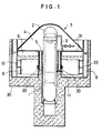
- cooling water is circulated in a reactor pressure vessel 2.
- a reactor pressure vessel 2 In the reactor pressure vessel 2, there is provided a core 1 of a nuclear reactor.
- a main steam line 3 is connected to the upper portion of the reactor pressure vessel 2.
- Cooling water in the reactor pressure vessel 2 is heated and is thereby converted into high temperature and high pressure steam, steam thus generating being then discharged outside the reactor pressure vessel 2 via the main steam line 3. Steam thus discharged outside the reactor pressure vessel 2 is utilized as a power source for a turbine generator similar to ordinary nuclear power plants. Steam which has been utilized is condensed and is returned, as cooling water, into the reactor pressure vessel 2.
- a primary containment vessel 7 is a steel structure erecting on a base mat 30, the primary containment vessel 7 being sectioned into a dry-well volume 4 and a suppression chamber 31.
- the dry-well volume 4 accommodates the reactor pressure vessel 2, and the suppression chamber 31 is formed to surround the reactor pressure vessel 2.
- the suppression chamber 31 containing cooling water as pool water comprises a suppression pool 6 in liquid phase and a wet-well volume 9 in gaseous phase.
- the dry-well volume 4 and the suppression pool 6 are connected to each other by a plurality of vent tubes 5.
- An outlet 20 of the vent tube 5 is arranged to open horizontally at a position higher than a top of the core 1 of the reactor.
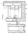
- a baffle plate 10 is disposed in the suppression pool 6 along the inner surface of the primary containment vessel 7.
- the baffle plate 10 is supported in such a manner that the baffle plate 10 is fastened to supports 23 secured to the wall of the primary containment vessel 7 and it does not partition between the water surface of the suppression pool 6 and the top end of the baffle plate 10 and between the bottom of the suppression pool 6 and the lower end of the baffle plate 10. It is arranged such that the distance from the top end of the baffle plate 10 to the water surface of the suppression pool 6 and the distance from the lower end of the baffle plate 10 to the bottom of the suppression pool 6 are substantially equal and is larger than the distance from the baffle plate 10 to a wall 22 of the primary containment vessel 7. As shown in Fig.
- the baffle plate 10 is disposed in the suppression pool 6 in such a manner that the height h1 of the top end of the baffle plate 10 from a reference position, which is the height of the outlet 20 of the vent tube 5, and the depth h3 of the lower end of the baffle plate 10 holds the relationship h1 > h3.
- the outlet 20 of the vent tube 5 is positioned lower than the middle point of the height of the baffle plate 10, that is, it is positioned lower than the middle point of the depth of water in the suppression pool 6.
- a core equalizing line 11 establishes a connection between a portion of the suppression pool 6 lower than the outlet 20 of the bent tube 5 by h2 and a portion of the reactor pressure vessel 2 upper than the top end of the core 1, the connection being established via a check-valve 21.
- the check-valve 21 prevents the cooling water in the reactor pressure vessel 2, which becomes high pressure at a normal operation, from flowing backward into the suppression pool 6.
- An outer pool 8 is formed around a suppression chamber 31 of the primary containment vessel 7.
- the outer pool 8 is filled with cooling water. Cooling water in the outer pool 8 surrounds the suppression chamber 31 and is in contact with the wall 22 of the primary containment vessel 7.
- the outer pool 8 has a gaseous-phase portion in the upper portion thereof, the gaseous-phase portion being opened in another space in order to cause water in the outer pool 8 to be easily evaporated.
- the water surface of the suppression pool 6 moves vertically considerably since the water surface of the suppression pool 6 stands up or the buoyancy of the bubbles of the noncondensing gas acts or due to an action of the burst of the bubbles expanded during the upward movement of the bubbles at the water surface. Therefore, a large impact load can act on the ceiling of the suppression chamber 31.
- the outlet 20 of the vent tube 5 is disposed at an intermediate depth of water in the suppression pool 6, the movement or standing up of the water surface of the suppression pool 6 can be reduced. Therefore, the ceiling of the suppression chamber 31 can be satisfactorily protected from damage.
- Hot water in the suppression pool 6 is introduced into the inner wall of the primary containment vessel 7 at which it is cooled and is moved downwards below the outlet 20 of the vent tube 5. Therefore, the region in which hot water exists can be widened downwards, the region being limited in a portion higher than the outlet 20 of the vent tube 5 in the conventional structure. Therefore, the heat transfer surface from hot water in the suppression pool 6 to the outer pool 8 can be increased, causing the heat radiation efficiency from the primary containment vessel 7 to be improved.
- Water in the outer pool which has received heat from the primary containment vessel 7, starts evaporation at the evaporating temperature so that heat of vaporization is discharged outside.
- Fig. 3B illustrates a temperature distribution on the inside and the outside of the baffle plate 10 in the direction of its height, the temperature distribution being estimated in the case where a downward flow is formed on the outside of the baffle plate 10.
- symbol E represents the height
- T represents the temperature of water in the suppression pool 6
- WL represents the water surface
- B1 represents the top end of the baffle plate 10
- VT represents the outlet 20 of the vent tube 5
- B2 represents the lower end of the baffle plate 10.
- the temperature of a region inside the baffle plate 10 and upper than the outlet 20 of the vent tube 5 becomes T1 due to a natural circulation caused by heat generated by a condensation taken place in the vicinity of the outlet 20.
- the temperature of a region outside the baffle plate 10 and upper than the top end of the baffle plate 10 becomes T1 which is the same as that inside the baffle plate 10.
- the downward flow passing outside the baffle plate 10 is cooled due to the heat transfer to the outer pool 8 so that it becomes T2 at the lower end of the baffle plate 10. Assuming that the heat radiation characteristics to the outer pool 8, that is, the convection heat transfer ratio is constant, the temperature is, as illustrated, lowered linearly between the top end and the lower end of the baffle plate 10.
- the temperature of water in the portion inside the baffle plate 10 and lower than the outlet 20 of the bent tube 5 becomes T2.
- the temperature T2 is determined by the conditions in which the balance between the inside portion and the outside portion is arranged.
- T0 which is the initial temperature.
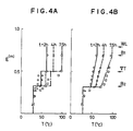
- FIG. 4A illustrates a temperature distribution of water in the suppression pool 6 in a portion inside the baffle plate 10
- Fig. 4B illustrates a temperature distribution of water in the suppression pool 6 in a portion outside the baffle plate 10.
- symbol t represents the lapse of time taken from the start of the steam introduction
- E, T, WL, B1, VT and B2 represent the same factors as those shown in Fig. 3B.
- Points of measurement show the measured temperature at each of the heights at 2, 4 and 7.5 hours after the steam introduction from the dummy of the vent tube 5 of the device has been started, while lines show the analytical result with the above-described model. As is shown, the experimental result and the analytical result significantly coincide with each other. Therefore, it is apparent the employed model is a suitable model.
- Equation (1) p(T1)h1 + p(T2)h3 ⁇ p ⁇ (T1 + T2)/2 ⁇ (h1 + h3) (1)
- p(T) represents the density of water at temperature T
- the other symbols represent the heights and temperatures shown in Figs. 2 and 3B.
- T2 T0.
- Equation (2) (h3 - h1)(T1 - T0) ⁇ 0 (2)
- the condition for causing the circulation between the inside and the outside portions of the baffle plate 10 is the relationship h3 ⁇ h1, which meets Equation (2), between height of the baffle plate 10 and that of the outlet 20 of the vent tube 5. If the baffle plate 10 is lengthened downwards excessively, no downward flow is generated outside the baffle plate 10. Such a long baffle plate 10 acts as an obstruction since it has not effect.
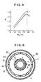
- Fig. 5 illustrates a change in the heat accumulating characteristics and in the heat radiation characteristics when h1 is arranged to be 2.7 m and h3 is changed in the above-described conditions in an actual system in which the depth of water of the vent tube is 3.7 m.
- a continuous line shows the heat radiation characteristics, where symbol R represents the ratio of the characteristics in the case where no baffle plate is provided.
- Fig. 5 shows the change in the heat accumulating characteristics and the heat radiation characteristics with respect to those shown in the case where the baffle plate 10 is not provided.
- the high temperature region on both the inside and the outside portions of the baffle plate 10 extends downward over the outlet 20 of the vent tube 5 in proportion to the value h3. Therefore, both the heat accumulating characteristics and the heat radiation characteristics are improved.
- a second embodiment of the present invention is shown in Fig. 6.
- a plurality of the outlets 20 of the vent tube 5 are provided in the suppression pool 6.
- the supports 23 for supporting the baffle plate 10 in the suppression pool 6 are disposed at positions corresponding to the outlets 20 of the vent tube 5 in the circumferential direction, that is, are disposed on an extension in the radial direction of the outlet 20, the supports 23 establishing connections between the baffle plate 10 and the wall 22 of the primary containment vessel 7.
- the other portions are the same as those according to the first embodiment.
- noncondensing gas in the dry-well volume jets out from the outlet 20 of the vent tube 5 at the time of the accident so as to push water in the suppression pool 6 toward the baffle plate 10. Therefore, a large dynamic load generates in the circumferential portions corresponding to the outlets 20 of the vent tube 5, that is, in the direction of the horizontal extension of the outlets 20 of the vent tube 5. Since the baffle plate 10 is supported by the baffle plate 23 at the portion on which the large dynamic load acts, the required strength of the baffle plate 10 achieved by its thickness or the like can be reduced.
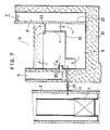
- FIG. 7 A third embodiment of the present invention is shown in Fig. 7.
- the immersed portion of the vertical cross sectional shape of the baffle plate 10 in the suppression pool 6 is arranged to be in the form of a step.
- the baffle plate 10 is positioned close to the wall 22 of the primary containment vessel 7 in the portion upper than the height of the outlet 20 o f the vent tube 5.
- the baffle plate 10 is positioned close to the inside wall of the suppression chamber 31 provided with outlet 20 of the vent tube 5 in the portion lower than the outlet 20 of the vent tube 5.
- the others are the same as those according to the first embodiment.
- the influence of the dynamic load generated in the suppression pool 6 due to the noncondensing gas jetted out in the beginning of the accident must be considered in a portion above the outlet 20 of the vent tube 5 since the noncondensing gas has a buoyancy.
- its structure is arranged such that the baffle plate 10 is positioned close to the outlet 20 in the region lower than the outlet 20 in which the effect of the dynamic load must not be considered. Therefore, such an arrangement does not cause any problem.
- the baffle plate 10 is positioned close to the outlet 20 of the baffle plate 10 in the region lower than the height of the outlet 20 of the vent tube 5.
- hot water in the suppression pool 6 can be moved to a region adjacent to the bottom of the suppression pool 6 by the convection.
- the convection can be induced horizontally, the overall water in the suppression pool 6 can be utilized as the heat accumulating pool including water in the bottom of the suppression pool 6.
- the temperature of water outside of the baffle plate 10 is higher than that inside of the same. Therefore, hot water region outside of the baffle plate 10 can be spread along the depth of water, causing the heat accumulating performance of the suppression pool 6 to be enhanced. Therefore, according to the third embodiment, the heat accumulating characteristics of the suppression chamber can be improved.
- the heat accumulating performance and the heat radiation performance of the suppression chamber 31 can be improved without the necessity of enlarging the suppression pool 6. Since the heat accumulating performance and the heat radiation performance of the suppression chamber 31 can be improved without the necessity of enlarging the suppression pool 6, the primary containment vessel 7 including the suppression chamber 31 can be reduced in size.
- the convection region of water in the suppression pool 6 can be vertically enlarged by virtue of the baffle plate 10, the water depth to the outlet 20 of the vent tube 5 can, for example, be reduced by about 40%. Therefore, the height of the ceiling of the suppression chamber 31 necessary to prevent the ceiling of the same from a damage can be reduced, the damage being due to pool swell taken place in the beginning of the accident, that is due to the standing up of the water surface caused by the noncondensing gas jetted out from the outlet 20 of the vent tube 5. Namely, the bottom of the dry-well volume in which the main steam line 3 is arranged can be lowered.
- the equalizing line 11 can also be reduced in accordance with the structure in which the water depth to the outlet 20 of the vent tube 5 is reduced. Therefore, the top end of the core 1 can be raised. Since the position of the core 1 can be raised, the vertical size of the reactor pressure vessel 2 can be reduced.
- the height of the reactor pressure vessel 2, that is the primary containment vessel 7 can be reduced.
- the necessary strength of the primary containment vessel 7 can be reduced.
Landscapes
- Physics & Mathematics (AREA)
- Engineering & Computer Science (AREA)
- Plasma & Fusion (AREA)
- General Engineering & Computer Science (AREA)
- High Energy & Nuclear Physics (AREA)
- Structure Of Emergency Protection For Nuclear Reactors (AREA)
Applications Claiming Priority (2)
| Application Number | Priority Date | Filing Date | Title |
|---|---|---|---|
| JP1118369A JPH0718941B2 (ja) | 1989-05-11 | 1989-05-11 | 原子炉格納容器 |
| JP118369/89 | 1989-05-11 |
Publications (2)
| Publication Number | Publication Date |
|---|---|
| EP0397162A1 true EP0397162A1 (de) | 1990-11-14 |
| EP0397162B1 EP0397162B1 (de) | 1994-03-16 |
Family
ID=14734999
Family Applications (1)
| Application Number | Title | Priority Date | Filing Date |
|---|---|---|---|
| EP90108798A Expired - Lifetime EP0397162B1 (de) | 1989-05-11 | 1990-05-10 | Primärsicherheitseinschluss mit äusserem Wasserbecken |
Country Status (4)
| Country | Link |
|---|---|
| US (1) | US5021212A (de) |
| EP (1) | EP0397162B1 (de) |
| JP (1) | JPH0718941B2 (de) |
| DE (1) | DE69007327T2 (de) |
Cited By (2)
| Publication number | Priority date | Publication date | Assignee | Title |
|---|---|---|---|---|
| EP0492899A1 (de) * | 1990-12-20 | 1992-07-01 | General Electric Company | Hydraulische Druckausgleichsvorrichtung zum Abbau eines Vakuums |
| EP0599613A1 (de) * | 1992-11-25 | 1994-06-01 | General Electric Company | Kernreaktorgebäude mit Scheidewand in der Kondensationskammer |
Families Citing this family (10)
| Publication number | Priority date | Publication date | Assignee | Title |
|---|---|---|---|---|
| US5295169A (en) * | 1990-10-15 | 1994-03-15 | Hitachi, Ltd. | Reactor containment facilities |
| US5169595A (en) * | 1991-09-03 | 1992-12-08 | General Electric Company | Reactor core isolation cooling system |
| JP2003329789A (ja) * | 2002-05-16 | 2003-11-19 | Ishikawajima Harima Heavy Ind Co Ltd | シールドビルディング |
| DE10258354B3 (de) * | 2002-12-12 | 2004-07-29 | Framatome Anp Gmbh | Sicherheitsbehälter einer Kernkraftanlage |
| US8588360B2 (en) * | 2007-11-15 | 2013-11-19 | The State Of Oregon Acting By And Through The State Board Of Higher Education On Behalf Of Oregon State University | Evacuated containment vessel for a nuclear reactor |
| US9984777B2 (en) | 2007-11-15 | 2018-05-29 | Nuscale Power, Llc | Passive emergency feedwater system |
| US8867690B2 (en) * | 2011-08-25 | 2014-10-21 | Babcock & Wilcox Mpower, Inc. | Pressurized water reactor with compact passive safety systems |
| US9053823B2 (en) * | 2011-12-19 | 2015-06-09 | Ge-Hitachi Nuclear Energy Americas Llc | Method and apparatus for an alternative suppression pool cooling for boiling water reactors |
| JP6285337B2 (ja) * | 2014-10-17 | 2018-02-28 | 日立Geニュークリア・エナジー株式会社 | 原子炉格納容器 |
| CN106898389A (zh) * | 2015-12-21 | 2017-06-27 | 中国核动力研究设计院 | 一种固有安全的安全壳抑压冷却系统 |
Citations (3)
| Publication number | Priority date | Publication date | Assignee | Title |
|---|---|---|---|---|
| DE1227160B (de) * | 1959-02-24 | 1966-10-20 | Gen Electric | Kernreaktoranlage |
| LU79240A1 (fr) * | 1977-06-23 | 1978-06-29 | Babcock & Wilcox Co | Enceinte pour generateur nucleaire de vapeur |
| EP0030698A2 (de) * | 1979-12-17 | 1981-06-24 | Ab Asea-Atom | Siedewasserreaktor |
Family Cites Families (8)
| Publication number | Priority date | Publication date | Assignee | Title |
|---|---|---|---|---|
| GB1463148A (en) * | 1973-12-12 | 1977-02-02 | Commissariat Energie Atomique | Liquid cooled nuclear reactors |
| JPS6131837A (ja) * | 1984-07-23 | 1986-02-14 | Matsushita Seiko Co Ltd | レンジフ−ド |
| JPS6333697A (ja) * | 1986-07-29 | 1988-02-13 | 株式会社東芝 | 格納容器熱除去装置 |
| JPH07117596B2 (ja) * | 1986-09-19 | 1995-12-18 | 株式会社日立製作所 | 自然放熱型格納容器 |
| JPS63229390A (ja) * | 1987-03-18 | 1988-09-26 | 株式会社日立製作所 | 原子炉 |
| JP2616973B2 (ja) * | 1988-09-02 | 1997-06-04 | 株式会社日立製作所 | 原子炉格納容器内の圧力低減構造 |
| JPH0296689A (ja) * | 1988-10-04 | 1990-04-09 | Hitachi Ltd | 原子炉の格納容器 |
| JP6131837B2 (ja) | 2013-11-15 | 2017-05-24 | マツダ株式会社 | 車両の前部構造 |
-
1989
- 1989-05-11 JP JP1118369A patent/JPH0718941B2/ja not_active Expired - Lifetime
-
1990
- 1990-05-10 EP EP90108798A patent/EP0397162B1/de not_active Expired - Lifetime
- 1990-05-10 DE DE69007327T patent/DE69007327T2/de not_active Expired - Fee Related
- 1990-05-11 US US07/522,033 patent/US5021212A/en not_active Expired - Fee Related
Patent Citations (3)
| Publication number | Priority date | Publication date | Assignee | Title |
|---|---|---|---|---|
| DE1227160B (de) * | 1959-02-24 | 1966-10-20 | Gen Electric | Kernreaktoranlage |
| LU79240A1 (fr) * | 1977-06-23 | 1978-06-29 | Babcock & Wilcox Co | Enceinte pour generateur nucleaire de vapeur |
| EP0030698A2 (de) * | 1979-12-17 | 1981-06-24 | Ab Asea-Atom | Siedewasserreaktor |
Non-Patent Citations (2)
| Title |
|---|
| NUCLEAR TECHNOLOGY, vol. 82, no. 2, August 1988, pages 147-156, La Grange Park, Illinois, US; Y. KATAOKA et al.: "Conceptual design and thermal-hydraulic characteristics of natural circulation boiling water reactors" * |
| NUCLEAR TECHNOLOGY. vol. 82, no. 2, 01 August 88, LA GRANGE PARK, ILLI pages 147 - 156; KATAOKA et AL.: "CONCEPTUAL DESIGN AND THERMAL HYDRAULIC CHARACTERISTICS OF NATURAL CIRCULATION BOILING WATER REACTORS" * |
Cited By (2)
| Publication number | Priority date | Publication date | Assignee | Title |
|---|---|---|---|---|
| EP0492899A1 (de) * | 1990-12-20 | 1992-07-01 | General Electric Company | Hydraulische Druckausgleichsvorrichtung zum Abbau eines Vakuums |
| EP0599613A1 (de) * | 1992-11-25 | 1994-06-01 | General Electric Company | Kernreaktorgebäude mit Scheidewand in der Kondensationskammer |
Also Published As
| Publication number | Publication date |
|---|---|
| US5021212A (en) | 1991-06-04 |
| DE69007327D1 (de) | 1994-04-21 |
| EP0397162B1 (de) | 1994-03-16 |
| JPH0718941B2 (ja) | 1995-03-06 |
| JPH02297097A (ja) | 1990-12-07 |
| DE69007327T2 (de) | 1994-06-30 |
Similar Documents
| Publication | Publication Date | Title |
|---|---|---|
| US7522693B2 (en) | Passive safety-grade decay-heat removal method and decay-heat removal system for LMR with pool direct heat cooling process | |
| EP0397162B1 (de) | Primärsicherheitseinschluss mit äusserem Wasserbecken | |
| KR101366218B1 (ko) | 원자로 및 원자로의 반응로 코어 냉각 방법 | |
| US11901088B2 (en) | Method of heating primary coolant outside of primary coolant loop during a reactor startup operation | |
| CN105960680B (zh) | 整体式反应堆压力容器管板 | |
| JP2016523355A (ja) | 受動的反応炉冷却システム | |
| JPH0262999A (ja) | 加圧水型原子炉 | |
| JPH05264775A (ja) | 原子炉スチーム隔離冷却システム | |
| US5353318A (en) | Pressure suppression system | |
| JPH0727055B2 (ja) | 原子炉容器用の受動熱除去系 | |
| JP2015508486A (ja) | 閉鎖伝熱経路を用いる、原子炉用緊急炉心冷却システム(eccs) | |
| EP0200989A2 (de) | Wendeldampferzeuger mit Doppelrohren | |
| JP3507547B2 (ja) | 圧力抑制式格納容器系 | |
| US5491730A (en) | Cooling system for primary containment vessel in nuclear power plant and component for use in said cooling system | |
| US5211906A (en) | Reactor containment vessel | |
| JP2007229661A (ja) | 気水分離器 | |
| JP2015529820A (ja) | 原子力発電プラントの補機冷却水システム | |
| US5511102A (en) | Apparatus for draining lower drywell pool water into suppresion pool in boiling water reactor | |
| JP2903819B2 (ja) | 原子炉格納容器の圧力抑制設備 | |
| US12512230B2 (en) | Passively-cooled spent nuclear fuel pool system | |
| US4554129A (en) | Gas-cooled nuclear reactor | |
| US4909981A (en) | Nuclear reactor | |
| KR102583804B1 (ko) | 피동 안전 계통을 구비한 소형 모듈 원자로 | |
| US4761261A (en) | Nuclear reactor | |
| JP2021189152A (ja) | ドライ式の原子炉格納容器、及び、当該原子炉格納容器を備える原子力発電プラント |
Legal Events
| Date | Code | Title | Description |
|---|---|---|---|
| PUAI | Public reference made under article 153(3) epc to a published international application that has entered the european phase |
Free format text: ORIGINAL CODE: 0009012 |
|
| 17P | Request for examination filed |
Effective date: 19900907 |
|
| AK | Designated contracting states |
Kind code of ref document: A1 Designated state(s): DE SE |
|
| 17Q | First examination report despatched |
Effective date: 19930624 |
|
| GRAA | (expected) grant |
Free format text: ORIGINAL CODE: 0009210 |
|
| AK | Designated contracting states |
Kind code of ref document: B1 Designated state(s): DE SE |
|
| REF | Corresponds to: |
Ref document number: 69007327 Country of ref document: DE Date of ref document: 19940421 |
|
| PLBE | No opposition filed within time limit |
Free format text: ORIGINAL CODE: 0009261 |
|
| STAA | Information on the status of an ep patent application or granted ep patent |
Free format text: STATUS: NO OPPOSITION FILED WITHIN TIME LIMIT |
|
| EAL | Se: european patent in force in sweden |
Ref document number: 90108798.1 |
|
| 26N | No opposition filed | ||
| PGFP | Annual fee paid to national office [announced via postgrant information from national office to epo] |
Ref country code: SE Payment date: 19960425 Year of fee payment: 7 |
|
| PGFP | Annual fee paid to national office [announced via postgrant information from national office to epo] |
Ref country code: DE Payment date: 19960730 Year of fee payment: 7 |
|
| PG25 | Lapsed in a contracting state [announced via postgrant information from national office to epo] |
Ref country code: SE Effective date: 19970511 |
|
| EUG | Se: european patent has lapsed |
Ref document number: 90108798.1 |
|
| PG25 | Lapsed in a contracting state [announced via postgrant information from national office to epo] |
Ref country code: DE Free format text: LAPSE BECAUSE OF NON-PAYMENT OF DUE FEES Effective date: 19980203 |