EP0397064B1 - Procedure for mounting the guide rails for an elevator car or counterweight, and a mounting system implementing the procedure - Google Patents
Procedure for mounting the guide rails for an elevator car or counterweight, and a mounting system implementing the procedure Download PDFInfo
- Publication number
- EP0397064B1 EP0397064B1 EP90108484A EP90108484A EP0397064B1 EP 0397064 B1 EP0397064 B1 EP 0397064B1 EP 90108484 A EP90108484 A EP 90108484A EP 90108484 A EP90108484 A EP 90108484A EP 0397064 B1 EP0397064 B1 EP 0397064B1
- Authority
- EP
- European Patent Office
- Prior art keywords
- plates
- intermediate beam
- guide rails
- bolts
- procedure
- Prior art date
- Legal status (The legal status is an assumption and is not a legal conclusion. Google has not performed a legal analysis and makes no representation as to the accuracy of the status listed.)
- Expired - Lifetime
Links
Images
Classifications
-
- B—PERFORMING OPERATIONS; TRANSPORTING
- B66—HOISTING; LIFTING; HAULING
- B66B—ELEVATORS; ESCALATORS OR MOVING WALKWAYS
- B66B7/00—Other common features of elevators
- B66B7/02—Guideways; Guides
- B66B7/023—Mounting means therefor
- B66B7/027—Mounting means therefor for mounting auxiliary devices
-
- B—PERFORMING OPERATIONS; TRANSPORTING
- B66—HOISTING; LIFTING; HAULING
- B66B—ELEVATORS; ESCALATORS OR MOVING WALKWAYS
- B66B19/00—Mining-hoist operation
- B66B19/002—Mining-hoist operation installing or exchanging guide rails
-
- Y—GENERAL TAGGING OF NEW TECHNOLOGICAL DEVELOPMENTS; GENERAL TAGGING OF CROSS-SECTIONAL TECHNOLOGIES SPANNING OVER SEVERAL SECTIONS OF THE IPC; TECHNICAL SUBJECTS COVERED BY FORMER USPC CROSS-REFERENCE ART COLLECTIONS [XRACs] AND DIGESTS
- Y10—TECHNICAL SUBJECTS COVERED BY FORMER USPC
- Y10T—TECHNICAL SUBJECTS COVERED BY FORMER US CLASSIFICATION
- Y10T29/00—Metal working
- Y10T29/49—Method of mechanical manufacture
- Y10T29/49826—Assembling or joining
- Y10T29/49828—Progressively advancing of work assembly station or assembled portion of work
Definitions
- the present invention relates to a procedure for mounting the guide rails for an elevator car or counterweight, and to a mounting system implementing the procedure, in which the guide rails are attached to an intermediate beam, which in turn is attached by its ends to opposite walls of the elevator shaft.
- Intermediate beams are used to divide an elevator shaft vertically into two or more parts forming channels for separate cars moving along guide rails attached to the intermediate beams.
- Guide rails attached to intermediate beams can also be used to mount counterweights or to accommodate an elevator car in an oversized shaft.
- the guide rails for elevator cars or counterweights are secured on the intermediate beams by welding, using various bars and/or plates to connect the vertical rails to the horizontal intermediate beams, which in turn are secured by welding their ends on mounting racks provided on opposite walls of the shaft or by casting the beams in the wall structure during the building stage.
- the object of the present invention is to eliminate the above-mentioned drawbacks and to achieve a procedure for mounting the guide rails and associated supporting structures in an elevator shaft enabling a precisely straight alignment of the guide rails to be easily achieved and the rails to be securely mounted without welded joints.
- the procedure of the invention is characterized by claim 1.
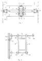
- Figs. 1 and 2 illustrate a general embodiment of the elevator guide rail mounting system of the invention.
- the shaft 1 is divided into two spaces A and B accommodating elevator cars 3 and 4.
- Placed oppositely on the sides of the box-like intermediate beam 2 are two steel plates 5 and 6, the upper and lower edges of which extend above and below the intermediate beam 2 so that the plates 5,6 can be pressed against the intermediate beam 2 by means of threaded bolts 7a,7b,8b and 8a (not shown in the figure) connecting the plates by their upper and lower edges.
- the car rails 11,12 are secured on the intermediate beam 2 by means of angle iron brackets 13 and 14 fastened at the ends of the upper bolts 7a,7b.
- the angle iron brackets are secured with nuts on the ends of the threaded bolts in such manner that the retention claws 15 of the brackets will receive the guide rails 11,12, installed in a vertical position, and lock them in place.
- the angle iron brackets are provided with oval or elongated holes for the threaded bolts 7a,7b to allow transverse adjustment of the bracket position relative to the bolts.
- the attachment of the elevator rails can be implemented using various techniques obvious to the person skilled in the art and is therefore outside the scope of the present invention.
- the car rails can also be secured by means of angle irons attached to the lower bolt 8b, in which case there are two points of attachment of the rail.
- the friction joint solution illustrated by figs. 1 and 2 substantially facilitates the installation and repair of elevator guide rails.
- the guide rails or rail mountings for an elevator car or counterweight can be attached to the intermediate beams by means of threaded bolts pressing the plates against the beam, the rails can be roughly aligned by adjusting the nuts pressing the plates together, and the fine adjustment of the alignment can be accomplished by adjusting the nuts holding the rails 11,12 or their mountings 13,14.
- the basic idea of the invention is also applied to the attachment of the intermediate beam 2 to the walls of the elevator shaft 1.
- the intermediate beam is attached by its ends to opposite walls of the shaft by means of two suitably bent steel plates 16,17 secured on the wall and with their upper and lower edges extending above and below the intermediate beam, said plates 16,17 being pressed against the intermediate beam 2 by threaded bolts 18a,18b (the lower one is not visible in the figure) connecting the plates and located above and below the beam 2, which is held in place by the friction joint thus produced.
- the steel plates 16,17 are secured on the shaft wall 1 by means of bolts 19, but in a building with a steel framework they can just as well be welded onto the wall or secured on specific points using various mounting fixtures.
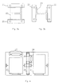
- Fig. 3 illustrates the manner in which the intermediate beam can be mounted in the shaft when an ordinary I-beam is used, which is the preferable type of beam in the case of heavy elevators.
- the angle iron brackets 21,22 holding the I-beam 20 are fastened to the shaft wall e.g. by means of four bolts and the intermediate beam 20 is mounted between them and tightened in place as shown in fig. 3a or 3b along the principles described above.
- the mountings of the car or counterweight guide rails can likewise be fastened to the intermediate beam as explained in connection with figs. 1 and 2.
- Fig. 4 shows an example of a shaft layout plan implemented using intermediate beams.
- the shaft accommodates two elevator cars 23,24 with an intermediate beam 25 as provided by the invention between them.
- the guide rails for the counterweight 26 of one 23 of the cars are mounted in the traditional manner on brackets 27 protruding from the shaft wall, whereas the guide rails for the counterweight 28 of the other car 24 are mounted on the intermediate beam.
- the attachment of both the guide rails for the counterweight and those for the car is implemented as provided by the invention, but it can also be implemented using any other known techniques.
- the essential point is that the mounting system of the invention using intermediate beams provides more feedom of design of the layout of the car and counterweight guide rails in the elevator shaft.
Landscapes
- Cage And Drive Apparatuses For Elevators (AREA)
- Lift-Guide Devices, And Elevator Ropes And Cables (AREA)
- Heat Treatment Of Sheet Steel (AREA)
- Types And Forms Of Lifts (AREA)
Abstract
Description
- The present invention relates to a procedure for mounting the guide rails for an elevator car or counterweight, and to a mounting system implementing the procedure, in which the guide rails are attached to an intermediate beam, which in turn is attached by its ends to opposite walls of the elevator shaft.
- Intermediate beams are used to divide an elevator shaft vertically into two or more parts forming channels for separate cars moving along guide rails attached to the intermediate beams. Guide rails attached to intermediate beams can also be used to mount counterweights or to accommodate an elevator car in an oversized shaft.
- The guide rails for elevator cars or counterweights are secured on the intermediate beams by welding, using various bars and/or plates to connect the vertical rails to the horizontal intermediate beams, which in turn are secured by welding their ends on mounting racks provided on opposite walls of the shaft or by casting the beams in the wall structure during the building stage.
- The drawbacks of the previously known procedures for the mounting of guide rails include the difficulty of adjustment of the guide rails due to the rigid welded joints, and the precision requirements imposed by the installation safety considerations on the person performing the welding, who generally has received special training as an elevator installer, not as a welder. In practice, it is necessary to take the rather large tolerances of the intermediate beams and associated mounting fixtures into account, which retards the installation of the guide rails. Further problems result from the difficulty of supplying electricity for the welding equipment to the required parts of the elevator shaft and the insufficient rigidity of the structures involved in the welding operations (intermediate beams of open cross-section, simple mounting lugs in the walls, etc.) as against the torsional load resulting from frictional forces and the normal forces of the guide load. This ultimately leads to the distortion of the guide rails and a bumpy elevator travel.
- The object of the present invention is to eliminate the above-mentioned drawbacks and to achieve a procedure for mounting the guide rails and associated supporting structures in an elevator shaft enabling a precisely straight alignment of the guide rails to be easily achieved and the rails to be securely mounted without welded joints. The procedure of the invention is characterized by claim 1.
- The other preferred embodiments of the procedure of the invention are characterized by what is presented in the claims to follow.
- The system for mounting the guide rails for an elevator car or counterweight is characterized by
claim 4 and its subclaims. - In the following, the invention is described by the aid of examples by referring to the drawings attached, in which
- Fig. 1 presents the elevator guide rail mounting system as seen from above,
- Fig. 2 presents in a cross-sectional view the intermediate beam in the system of fig. 1, and the rail mountings,
- Figs. 3a-b present an embodiment of the system of the invention, and
- Fig. 4 illustrates an elevator shaft arrangement implemented using the system of the invention.
- Figs. 1 and 2 illustrate a general embodiment of the elevator guide rail mounting system of the invention. In this embodiment, using
intermediate beams 2 placed at even distances through the whole height of the elevator shaft, the shaft 1 is divided into two spaces A and B accommodatingelevator cars 3 and 4. Placed oppositely on the sides of the box-likeintermediate beam 2 are twosteel plates intermediate beam 2 so that theplates intermediate beam 2 by means of threadedbolts nuts plates intermediate beam 2, the resulting friction joint will hold theguide rails elevator car 3,4 fast on theintermediate beam 2. The lock nuts on the opposite sides of theplates nuts - The
car rails intermediate beam 2 by means ofangle iron brackets upper bolts 7a,7b. The angle iron brackets are secured with nuts on the ends of the threaded bolts in such manner that theretention claws 15 of the brackets will receive theguide rails bolts 7a,7b to allow transverse adjustment of the bracket position relative to the bolts. The attachment of the elevator rails can be implemented using various techniques obvious to the person skilled in the art and is therefore outside the scope of the present invention. The car rails can also be secured by means of angle irons attached to thelower bolt 8b, in which case there are two points of attachment of the rail. - As the position and orientation of the
steel plates intermediate beam 2 can be fully determined and easily changed due to the threaded bolt mounting, the friction joint solution illustrated by figs. 1 and 2 substantially facilitates the installation and repair of elevator guide rails. Thus, the guide rails or rail mountings for an elevator car or counterweight can be attached to the intermediate beams by means of threaded bolts pressing the plates against the beam, the rails can be roughly aligned by adjusting the nuts pressing the plates together, and the fine adjustment of the alignment can be accomplished by adjusting the nuts holding therails mountings - In fig. 1, the basic idea of the invention is also applied to the attachment of the
intermediate beam 2 to the walls of the elevator shaft 1. The intermediate beam is attached by its ends to opposite walls of the shaft by means of two suitablybent steel plates plates intermediate beam 2 by threadedbolts beam 2, which is held in place by the friction joint thus produced. - In fig. 1, the
steel plates bolts 19, but in a building with a steel framework they can just as well be welded onto the wall or secured on specific points using various mounting fixtures. - Fig. 3 illustrates the manner in which the intermediate beam can be mounted in the shaft when an ordinary I-beam is used, which is the preferable type of beam in the case of heavy elevators. The
angle iron brackets beam 20 are fastened to the shaft wall e.g. by means of four bolts and theintermediate beam 20 is mounted between them and tightened in place as shown in fig. 3a or 3b along the principles described above. The mountings of the car or counterweight guide rails can likewise be fastened to the intermediate beam as explained in connection with figs. 1 and 2. - Fig. 4 shows an example of a shaft layout plan implemented using intermediate beams. The shaft accommodates two
elevator cars intermediate beam 25 as provided by the invention between them. The guide rails for thecounterweight 26 of one 23 of the cars are mounted in the traditional manner onbrackets 27 protruding from the shaft wall, whereas the guide rails for thecounterweight 28 of theother car 24 are mounted on the intermediate beam. The attachment of both the guide rails for the counterweight and those for the car is implemented as provided by the invention, but it can also be implemented using any other known techniques. The essential point is that the mounting system of the invention using intermediate beams provides more feedom of design of the layout of the car and counterweight guide rails in the elevator shaft. - It is obvious to a person skilled in the art that different embodiments of the invention are not restricted to the examples described above, but that they may instead be varied within the scope of the following claims.
Claims (6)
- Procedure for mounting the guide rails (11,12) for an elevator car (3,4) or counterweight (26,28), in which procedure the guide rails (11,12) are attached to an intermediate beam (2,20,25) laid across the elevator shaft (1), said beam (2,20,25) being attached by its ends to opposite walls of the elevator shaft (1), characterized in that two steel plates (5,6) are placed oppositely on the vertical sides of the intermediate beam (2;20;25), the upper and lower edges of said plates extending somewhat above and below the intermediate beam (2;20;25), that the plates (5,6) are pressed against the intermediate beam by means of screwed joints comprising bolts or threaded bars (7a,7b,8a,8b) connecting the plates (5,6) and passing above and below the intermediate beam (2,20,25) so that the plates (5,6) held in position by the friction generated by the pressure between the plates (5,6) and intermediate beam (2,20,25), and that the car or counterweight guide rails (11,12) and/or their mountings (13,14,15) are secured on the plates (5,6) and/or bolts (7a,7b,8a,8b).
- Procedure according to claim 1, characterized in that the guide rails (11,12) for the elevator car or counterweight or their mountings (13,14,15) are attached to the intermediate beam by means of nuts (9a,9b,10a,10b) tightened on threaded bolts (7a,7b,8a,8b) pressing the steel plates (5,6) against the beam, and that the rails are roughly aligned by adjusting nuts (9a,9b) and the fine adjustment of the alignment is accomplished by adjusting the nuts (9a,9b) holding the rails (11,12) or their mountings (13,14,15).
- Procedure according to claim 1 or 2, characterized in that the intermediate beam (2;20;25) is attached by its ends to opposite walls (1) of the elevator shaft by means of two suitably bent steel plates (16,17) secured on the wall and with their upper and lower edges extending above and below the intermediate beam (2;20;25), that the plates (16,17) are pressed against the intermediate beam by means of bolts or threaded bars (18a, 18b) connecting the plates and located above and below the beam, and that the intermediate bead (2;20; 25) is held in place by the friction produced by the pressure between the beam (2;20;25) and the bent plates (16,17).
- Mounting system for implementing the procedure of claim 1, comprising an intermediate beam (2;20;25) laid across the elevator shaft (1) and attached by its ends to opposite walls of the elevator shaft (1), said beam (2,20,25) permitting the guide rails (11,12) to be secured on it, characterized in that the system consists of steel plates (5,6) placed oppositely on the vertical sides of the intermediate beam (2;20;25), the upper and lower edges of said plates (5,6) extending somewhat above and below the intermediate beam, and of screwed joints comprising bolts or threaded bars (7a,7b,8a, 8b) connecting the plates (5,6) and passing above and below the intermediate beam (2,20,25), enabling the plates (5,6) to be pressed against the intermediate beam (2,20,25), and elevator or counterweight guide rails (11,12) and/or their mountings (13,14,15) being secured on the plates (5,6) and/or the bolts or bars (7a,7b,8a,8b).
- System according to claim 4, characterized in that the elevator or counterweight guide rails (11,12) or their mountings (13,14,15) have been attached to the intermediate beam by means of nuts (9a,9b,10a,10b) threaded on bolts or bars (7a,7b,8a,8b), pressing the plates (5,6) against the beam, and that the rails can be roughly aligned by adjusting nuts (9a,9b) pressing the plates (5,6) together and the fine adjustment of the alignment is accomplished by adjusting the nuts (9a,9b) holding the rails (11,12) or their mountings (13,14,15).
- System according to claim 4 or 5, characterized in that the intermediate beam (2;20;25) has been attached by its ends to opposite walls (1) of the elevator shaft by means of two suitably bent steel plates (16,17) secured on the wall and with their upper and lower edges extending above and below the intermediate beam (2;20;25), that the plates (16,17) are pressed against the intermediate beam by means of bolts or threaded bars (18a, 18b) connecting the plates and located above and below the beam, and that the intermediate beam (2;20; 25) is held in place by the friction produced by the pressure between the beam (2;20;25) and the bent plates (16,17).
Applications Claiming Priority (2)
| Application Number | Priority Date | Filing Date | Title |
|---|---|---|---|
| FI892220 | 1989-05-09 | ||
| FI892220A FI83302C (en) | 1989-05-09 | 1989-05-09 | Procedure for fastening guide rails for lifts or counterweights and a fastening system which realizes the procedure |
Publications (2)
| Publication Number | Publication Date |
|---|---|
| EP0397064A1 EP0397064A1 (en) | 1990-11-14 |
| EP0397064B1 true EP0397064B1 (en) | 1995-01-25 |
Family
ID=8528384
Family Applications (1)
| Application Number | Title | Priority Date | Filing Date |
|---|---|---|---|
| EP90108484A Expired - Lifetime EP0397064B1 (en) | 1989-05-09 | 1990-05-05 | Procedure for mounting the guide rails for an elevator car or counterweight, and a mounting system implementing the procedure |
Country Status (7)
| Country | Link |
|---|---|
| US (1) | US5119908A (en) |
| EP (1) | EP0397064B1 (en) |
| AT (1) | ATE117657T1 (en) |
| AU (1) | AU620986B2 (en) |
| DE (1) | DE69016254T2 (en) |
| ES (1) | ES2066901T3 (en) |
| FI (1) | FI83302C (en) |
Families Citing this family (13)
| Publication number | Priority date | Publication date | Assignee | Title |
|---|---|---|---|---|
| WO1998029325A1 (en) * | 1996-12-31 | 1998-07-09 | Lee, David, Woon | Method of installing elevator cable and rail |
| JP2003192255A (en) * | 2001-12-20 | 2003-07-09 | Inventio Ag | Guide rail device for elevator |
| US20060130305A1 (en) * | 2002-08-21 | 2006-06-22 | Englot Micheal E | Wear strip replacement method and apparatus |
| CA2399316C (en) * | 2002-08-21 | 2005-10-25 | Michael Edward Englot | Wear strip replacement method and apparatus |
| AU2003277477A1 (en) * | 2002-11-06 | 2004-06-07 | Lixin Sun | A detection method of lift guide rail perpendicularity and a detector for implementing this method |
| FI124957B (en) * | 2012-06-05 | 2015-04-15 | Kone Corp | Middle bar for elevator |
| EP2993152B8 (en) * | 2014-09-04 | 2017-04-19 | KONE Corporation | Apparatus and method for aligning guide rails in an elevator shaft |
| EP3090976B1 (en) * | 2015-05-06 | 2020-03-04 | KONE Corporation | Apparatus and method for aligning guide rails and landing doors in an elevator shaft |
| EP3127849A1 (en) * | 2015-08-07 | 2017-02-08 | Kone Corporation | Guide rail arrangement and method for installing guide rails |
| WO2017050660A1 (en) * | 2015-09-21 | 2017-03-30 | Inventio Ag | Elevator shaft delimiting device in elevator systems |
| WO2019063356A1 (en) * | 2017-09-27 | 2019-04-04 | Inventio Ag | ALIGNMENT DEVICE AND METHOD FOR ASSEMBLING A GUIDE RAIL IN AN ACCESS TRAY OF AN ELEVATOR |
| EP4406896A1 (en) | 2023-01-30 | 2024-07-31 | Inventio Ag | Lift system with a first lift cabin and a second lift cabin |
| CN120677121A (en) | 2023-01-30 | 2025-09-19 | 因温特奥股份公司 | Elevator installation |
Family Cites Families (8)
| Publication number | Priority date | Publication date | Assignee | Title |
|---|---|---|---|---|
| US2848077A (en) * | 1956-01-24 | 1958-08-19 | Otis Elevator Co | Elevator guide rail fastener |
| US3851736A (en) * | 1973-03-20 | 1974-12-03 | Westinghouse Electric Corp | Apparatus and method for installing elevator hoistway equipment |
| US3982692A (en) * | 1974-07-19 | 1976-09-28 | R. Stahl Aufzuege Gmbh | Clamping means for elevator guide rails and the like |
| US3893219A (en) * | 1974-08-01 | 1975-07-08 | Otis Elevator Co | Apparatus and method for suspending elevator guide rails |
| US4345671A (en) * | 1980-03-12 | 1982-08-24 | Westinghouse Electric Corp. | Apparatus and method for installing elevator guide rails |
| US4431087A (en) * | 1981-05-29 | 1984-02-14 | Westinghouse Electric Corp. | Guide rail clamping method and assembly |
| US4593794A (en) * | 1984-04-23 | 1986-06-10 | Schindler Haughton Elevator Corporation | Apparatus and method for installing elevator rails |
| US4577729A (en) * | 1984-12-05 | 1986-03-25 | Westinghouse Electric Corp. | Guide rail clamping assembly |
-
1989
- 1989-05-09 FI FI892220A patent/FI83302C/en not_active IP Right Cessation
-
1990
- 1990-05-04 AU AU54670/90A patent/AU620986B2/en not_active Ceased
- 1990-05-05 ES ES90108484T patent/ES2066901T3/en not_active Expired - Lifetime
- 1990-05-05 EP EP90108484A patent/EP0397064B1/en not_active Expired - Lifetime
- 1990-05-05 DE DE69016254T patent/DE69016254T2/en not_active Expired - Fee Related
- 1990-05-05 AT AT90108484T patent/ATE117657T1/en not_active IP Right Cessation
- 1990-05-09 US US07/520,879 patent/US5119908A/en not_active Expired - Fee Related
Also Published As
| Publication number | Publication date |
|---|---|
| EP0397064A1 (en) | 1990-11-14 |
| FI83302B (en) | 1991-03-15 |
| DE69016254T2 (en) | 1995-05-24 |
| ES2066901T3 (en) | 1995-03-16 |
| ATE117657T1 (en) | 1995-02-15 |
| AU620986B2 (en) | 1992-02-27 |
| DE69016254D1 (en) | 1995-03-09 |
| US5119908A (en) | 1992-06-09 |
| FI83302C (en) | 1991-06-25 |
| AU5467090A (en) | 1990-11-15 |
| FI892220A0 (en) | 1989-05-09 |
| FI892220A7 (en) | 1990-11-10 |
Similar Documents
| Publication | Publication Date | Title |
|---|---|---|
| EP0397064B1 (en) | Procedure for mounting the guide rails for an elevator car or counterweight, and a mounting system implementing the procedure | |
| CA2131748C (en) | An adjustable mount for elevator guide rails | |
| US6446762B1 (en) | Elevator machine support frame mounted to hoistway wall | |
| KR102043665B1 (en) | Monitering system for railway vehicle under parts and installation method therefor | |
| US20030168291A1 (en) | Connector brackets | |
| CN112408150B (en) | Guide rail bracket assembly | |
| EP0585777B1 (en) | Intermediate member for fixing the guide rails to an elevator shaft | |
| JPH0952675A (en) | Elevator guide rail mounting device | |
| EP0425313B1 (en) | Mount system for elevator guide rails | |
| EP2174902B1 (en) | Elevator guide rail fixing brackets | |
| US5365855A (en) | Track for magnetic levitation trains with stator connection having shear loaded belts | |
| JP4552077B2 (en) | Crane stopper | |
| JP2833430B2 (en) | Beam holding structure in column-beam installation structure | |
| US5255609A (en) | Suspension support system for an overhead conveyor system with clamp type connectors which do not penetrate existing structure | |
| JPS6214057Y2 (en) | ||
| JPH0236803Y2 (en) | ||
| JPH04354782A (en) | Coupling structure for elevator guide rail and method of laying guide rail | |
| CN223912134U (en) | Shock attenuation mounting structure and cabinet body in cabinet | |
| CN217808138U (en) | Villa ladder adjustment type guide rail bracket subassembly | |
| CN111173176B (en) | Connecting node of assembled steel structure building external wall board and mounting method | |
| SU1525114A1 (en) | Crane track | |
| JP3219732B2 (en) | Panel mounting method | |
| JP2728962B2 (en) | Concrete panel support structure | |
| JPH079924Y2 (en) | Connection structure of columns and beams | |
| JPH05287831A (en) | Support structure for stair top floor panel |
Legal Events
| Date | Code | Title | Description |
|---|---|---|---|
| PUAI | Public reference made under article 153(3) epc to a published international application that has entered the european phase |
Free format text: ORIGINAL CODE: 0009012 |
|
| AK | Designated contracting states |
Kind code of ref document: A1 Designated state(s): AT BE CH DE DK ES FR GB GR IT LI LU NL SE |
|
| 17P | Request for examination filed |
Effective date: 19901228 |
|
| 17Q | First examination report despatched |
Effective date: 19931014 |
|
| GRAA | (expected) grant |
Free format text: ORIGINAL CODE: 0009210 |
|
| AK | Designated contracting states |
Kind code of ref document: B1 Designated state(s): AT BE CH DE DK ES FR GB GR IT LI LU NL SE |
|
| PG25 | Lapsed in a contracting state [announced via postgrant information from national office to epo] |
Ref country code: GR Free format text: LAPSE BECAUSE OF FAILURE TO SUBMIT A TRANSLATION OF THE DESCRIPTION OR TO PAY THE FEE WITHIN THE PRESCRIBED TIME-LIMIT Effective date: 19950125 Ref country code: DK Effective date: 19950125 Ref country code: BE Effective date: 19950125 Ref country code: AT Effective date: 19950125 |
|
| REF | Corresponds to: |
Ref document number: 117657 Country of ref document: AT Date of ref document: 19950215 Kind code of ref document: T |
|
| REF | Corresponds to: |
Ref document number: 69016254 Country of ref document: DE Date of ref document: 19950309 |
|
| ET | Fr: translation filed | ||
| REG | Reference to a national code |
Ref country code: ES Ref legal event code: FG2A Ref document number: 2066901 Country of ref document: ES Kind code of ref document: T3 |
|
| ITF | It: translation for a ep patent filed | ||
| PG25 | Lapsed in a contracting state [announced via postgrant information from national office to epo] |
Ref country code: LU Free format text: LAPSE BECAUSE OF NON-PAYMENT OF DUE FEES Effective date: 19950531 |
|
| PLBE | No opposition filed within time limit |
Free format text: ORIGINAL CODE: 0009261 |
|
| STAA | Information on the status of an ep patent application or granted ep patent |
Free format text: STATUS: NO OPPOSITION FILED WITHIN TIME LIMIT |
|
| 26N | No opposition filed | ||
| PGFP | Annual fee paid to national office [announced via postgrant information from national office to epo] |
Ref country code: FR Payment date: 19980409 Year of fee payment: 9 |
|
| PGFP | Annual fee paid to national office [announced via postgrant information from national office to epo] |
Ref country code: SE Payment date: 19980416 Year of fee payment: 9 |
|
| PGFP | Annual fee paid to national office [announced via postgrant information from national office to epo] |
Ref country code: GB Payment date: 19980417 Year of fee payment: 9 |
|
| PGFP | Annual fee paid to national office [announced via postgrant information from national office to epo] |
Ref country code: CH Payment date: 19980428 Year of fee payment: 9 |
|
| PGFP | Annual fee paid to national office [announced via postgrant information from national office to epo] |
Ref country code: DE Payment date: 19980429 Year of fee payment: 9 |
|
| PGFP | Annual fee paid to national office [announced via postgrant information from national office to epo] |
Ref country code: NL Payment date: 19980430 Year of fee payment: 9 |
|
| PGFP | Annual fee paid to national office [announced via postgrant information from national office to epo] |
Ref country code: ES Payment date: 19980513 Year of fee payment: 9 |
|
| PG25 | Lapsed in a contracting state [announced via postgrant information from national office to epo] |
Ref country code: GB Free format text: LAPSE BECAUSE OF NON-PAYMENT OF DUE FEES Effective date: 19990505 |
|
| PG25 | Lapsed in a contracting state [announced via postgrant information from national office to epo] |
Ref country code: SE Free format text: LAPSE BECAUSE OF NON-PAYMENT OF DUE FEES Effective date: 19990506 Ref country code: ES Free format text: LAPSE BECAUSE OF NON-PAYMENT OF DUE FEES Effective date: 19990506 |
|
| PG25 | Lapsed in a contracting state [announced via postgrant information from national office to epo] |
Ref country code: LI Free format text: LAPSE BECAUSE OF NON-PAYMENT OF DUE FEES Effective date: 19990531 Ref country code: CH Free format text: LAPSE BECAUSE OF NON-PAYMENT OF DUE FEES Effective date: 19990531 |
|
| PG25 | Lapsed in a contracting state [announced via postgrant information from national office to epo] |
Ref country code: NL Free format text: LAPSE BECAUSE OF NON-PAYMENT OF DUE FEES Effective date: 19991201 |
|
| GBPC | Gb: european patent ceased through non-payment of renewal fee |
Effective date: 19990505 |
|
| REG | Reference to a national code |
Ref country code: CH Ref legal event code: PL |
|
| EUG | Se: european patent has lapsed |
Ref document number: 90108484.8 |
|
| PG25 | Lapsed in a contracting state [announced via postgrant information from national office to epo] |
Ref country code: FR Free format text: LAPSE BECAUSE OF NON-PAYMENT OF DUE FEES Effective date: 20000131 |
|
| NLV4 | Nl: lapsed or anulled due to non-payment of the annual fee |
Effective date: 19991201 |
|
| PG25 | Lapsed in a contracting state [announced via postgrant information from national office to epo] |
Ref country code: DE Free format text: LAPSE BECAUSE OF NON-PAYMENT OF DUE FEES Effective date: 20000301 |
|
| REG | Reference to a national code |
Ref country code: FR Ref legal event code: ST |
|
| REG | Reference to a national code |
Ref country code: ES Ref legal event code: FD2A Effective date: 20010503 |
|
| PG25 | Lapsed in a contracting state [announced via postgrant information from national office to epo] |
Ref country code: IT Free format text: LAPSE BECAUSE OF NON-PAYMENT OF DUE FEES Effective date: 20050505 |